Note: Descriptions are shown in the official language in which they were submitted.
CA 02341073 2001-03-16
1
OPTICAL SENSING DEVICES
FIELD OF THE INVENTION
The present invention relates to optical devices for sensing substances in a
solution, and more particularly concerns an optical sensor, an optical nose
and a
method of making the latter.
BACKGROUND OF THE INVENTION
"Smell-detectors" or "electronic noses" are substance detecting devices
io based on a technique in full expansion which uses the absorption by
polymeric
membranes of analytes present in fluids. The absorption of the analytes by the
polymeric membranes generates an alteration of its physical properties, such
as
density, thickness, refractive index, resistivity, etc.
Electronic techniques for measuring these alterations of the properties of
the membrane are well documented. For example, the product named "Cyranose
320" (trademark) from the company Cyrano Sciences Inc. is based on such a
technique. Typically, an electronic nose is composed of many sensors made from
different polymers, each having its own reaction to the presence of a given
substance. Electronic noses generally measure the change in resistivity of the
polymer membranes. However, since polymers are rarely conductive, it is
usually
necessary to mix conductive particles, for example carbon-black, to the
polymeric
material, thereby increasing the conductivity of the membrane. Another major
drawback experienced by these devices is sensor drift, which creates the
necessity for frequent calibration or "retraining" of the sensors.
Optical based detecting techniques are also known in the art. In these
cases, the luminescence of the polymeric membrane when exposed to a given
analyte is measured and characterized. The following references study the
various
aspects of this technique: "Randomly Ordered Addressable High-Density Optical
Sensor Arrays" Michael, K.L., Taylor, L.C., Schultz, S.L., Walt, D.R., Anal.
Chem.
1998, 70, 1242-1248; "The Use of Optical-Imagining Fibers for the Fabrication
of
Array Sensors" Michael, K.L., Ferguson, J.A., Healy, B.G., Panova, A.A.,
Pantano,
CA 02341073 2001-03-16
2
P., Walt, D.R., American Chemical Society, 1998, 273-288; "Ordered Nanowell
Arrays" Pantano, P., Walt, D.R., Chem. Mater. 1996, 8, 2832-2835; "Combined
imaging and chemical sensing of fertilization-induced acid release from single
sea
urchin eggs"., Michael, K.L., Walt, D.R., Anal. Biochem., 1999, 273, 168-178;
"Convergent, Self-Encoded Bead Sensor Arrays in the Design of an Artificial
Nose" Dickinson, T.A., Michael, K.L., Kauer, J.S., Walt, D.R., Anal. Chem.,
1999,
71, 2192-2198; "Identification of Multiple Analytes Using an Optical Sensor
Array
and Pattern Recognition Neural Networks" Johnson, S.R., Sutter, J.M.,
Engelhardt, H.L., Jurs, P.C., White, J, Kauer, J.S., Dickinson, T.A., Walt,
D.R.,
1o Anal. Chem, 1997, 69, 4641-4648; "A Chemical-Detecting System based on a
cross-reactive optical sensor array", Dickinson, T.A., White, J., Kauer, J.S.,
Walt,
D.R., Nature, 1996, 382, 697-700; and "High-Speed Fluorescence Detection of
Explosives Vapor", Albert, K.J., Myrick, M.L., Brown, S.B., Milanovich, F.P.,
Walt,
D.R., SPIE, 1999, 3710, 308-314.
OBJECTS AND SUMMARY OF THE INVENTION
An object of the present invention is to provide a sensing device measuring
the change in thickness of the polymer membrane by optical means.
Another object of the invention is to provide such a sensing device for either
2o detecting a particular substance or identifying at least one substance in a
solution.
Yet another object of the present invention is to provide a method for
making such a device.
Accordingly, the present invention provides an optical sensor for detecting a
substance in a solution, comprising:
an optical fiber having a free extremity;
a polymer layer deposited on said free extremity of the optical fiber, said
polymer layer laying in a plane normal to a longitudinal axis of the optical
fiber, the
polymer layer having a thickness related to said substance when exposed
thereto;
a light source coupled to the optical fiber for injecting an analytical light
10 beam therein so that said analytical light beam is reflected by the polymer
layer to
define a reflected light beam; and
CA 02341073 2001-03-16
3
a spectrum analyzer coupled to the optical fiber for receiving the reflected
light beam and analyzing said reflected light beam to deduce therefrom the
thickness of the polymer layer.
In accordance with another object of the invention, there is provided an
optical nose for identifying at least one substance in a solution, said
optical nose
comprising:
a plurality of optical sensors, each comprising an optical fiber having a free
extremity and a polymer layer deposited on said free extremity, said polymer
layer
laying in a plane normal to a longitudinal axis of the optical fiber, at least
two of
io said polymer layers being of different types, each polymer layer having a
thickness
related to said at least one substance when exposed thereto;
a light source, coupled to the optical fiber of each of the optical sensors,
for
injecting an analytical light beam therein so that said analytical light beam
is
reflected by the corresponding polymer layer to define a reflected light beam;
and
is a spectrum analyzer coupled to the optical fiber of each of the optical
sensors, for receiving each of the reflected light beams, analyzing each of
said
reflected light beams to deduce therefrom the thickness of the corresponding
polymer layer, and identifying the at least one substance corresponding to
said
thicknesses.
2o Also, the present invention provides a method of making an optical nose for
identifying at least one substance in a solution, the method comprising the
steps
of:
a) providing a plurality of optical fibers, each having a free extremity;
b) depositing a polymer layer on the free extremity of each optical fiber in a
25 plane normal to a longitudinal axis of the optical fiber, at least two of
said polymer
layers being of different types, each polymer layer having a thickness related
to
the at least one substance when exposed thereto;
c) coupling each of the optical fibers to a light source for injecting an
analytical light beam therein, so that said analytical light beam is reflected
by the
30 corresponding polymer layer to define a reflected light beam;
CA 02341073 2007-08-23
4
d) coupling each of the optical fibers to a spectrum analyzer for receiving
each of the reflected light beams, and for analyzing each of said reflected
light
beams to deduce therefrom the thickness of the corresponding polymer layer;
and
e) exposing the optical nose to solutions including reference substances
and identifying the thicknesses of the polymer layers corresponding to said
reference substances.
Other features and advantages of the present invention will be better
understood upon reading the following description of preferred embodiments
thereof, with reference to the appended drawings.
BRIEF DESCRIPTION OF THE DRAWINGS
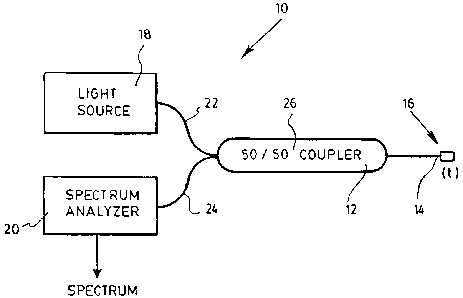
FIG. 1 is a schematic representation of an optical sensor according to an
embodiment of the present invention.
FIG. 2 is a schematic representation of an optical nose according to another
embodiment of the present invention; and FIG. 2A is an enlarged view of
section
2A of FIG. 2.
DESCRIPTION OF PREFERRED EMBODIMENTS OF THE INVENTION
With reference to FIG. 1, there is shown an optical sensor 10 for detecting a
substance in a solution in accordance with a first preferred embodiment of the
invention.
The sensor 10 first includes an optical fiber 12, which could be a typical
silica fiber or be made of any other appropriate material. The fiber 12 has a
free
extremity 14, which has been cut along the cross section of the fiber 12 so as
to
define a plane normal to its longitudinal axis. A polymer layer 16 is
deposited on
the free extremity 14, and extends in this normal plane. The polymer layer 16
has
a thickness t related to substance to be detected when exposed thereto, as
will be
further explained below. Any number of polymeric materials may be used
depending on the desired sensibility of the device. The same polymers as those
used for electronic noses may equally be chosen for the present invention.
Example of such polymers include polydimethylsiloxane (PDMS),
CA 02341073 2001-03-16
polyoctylmethylsiloxane (POMS), poly(isopropylcarboxylic acid)methylsiloxane
(PiPCAM S), poly(cyanopropyl)methylsiloxane (PCPMS), poly(aminopropyl)me-
thylsiloxane (PAPMS), poly(cyanopropyl)methylsiloxane (PCPMS), (etc.)
A light source 18 is coupled to the optical fiber 12. The light source
5 preferably emits an analytical light beam which is preferably a broadband
signal,
such as white light. A scanning in wavelength of the analytical light beam may
also
be considered. The analytical light beam is injected into the optical fiber
12,
wherein in propagates toward the polymer layer 16 where it is reflected at
least
partially. A reflected light beam is therefore generated in counter
propagation in
io the fiber 12. The reflected light beam is analyzed by a spectrum analyzer
20,
which is coupled to the optical fiber 12 for this purpose.
Preferably, a source fiber 22 is provided for conveying the analytical light
beam from the light source 18 to the optical fiber 12, and an analyzer fiber
24
conveys the reflected light beam from the optical fiber 12 to the spectrum
analyzer
20. A 50/50 coupler 26 is preferably provided for coupling the source fiber 22
and
analyzer fiber 24 to the optical fiber 12. In this manner, an optical beam
incident on
the coupler 26 is divided into two equal beams each transmitted in one of the
other
two branches connected to the coupler 26. This setup of course generates a
decrease in the useful signal intensity, and other coupling schemes may of
course
2o be devised in accordance with the general knowledge of those skilled in the
art
without departing from the scope of the present invention.
In use, the above described sensor operates as follows. The free extremity
14 of the fiber 12 is inserted in the solution containing the substance to be
detected. The particular polymer material of the layer 14 has been chosen to
have
a particular reaction to this given substance, that is that its thickness will
increase
to a known value when in its presence. The objective of the operation is
therefore
to measure this thickness. The analytical light beam is injected into the
fiber 12,
and is partially reflected when it encounters the refractive index change at
the
polymer layer's boundaries. Two such boundaries are present, a first one
between
3 o the optical fiber 12 and the polymer layer 16, and a second one between
the
polymer layer 16 and the solution media. Partial reflection occurring at both
CA 02341073 2001-03-16
6
boundaries, a periodic variation will be introduced in the reflected light
beam, in
accordance with the Fabry-Perot effect. This shift is directly related to the
thickness of the polymer layer. Using interferometric, refractive or
diffractive
analyzing techniques well known of those in the art, the thickness of the
polymeric
layer may be deduced by the analyzer 20 from the spectrum of the reflected
light
beam.
With reference to FIG. 2 there is shown an optical nose 30 for identifying at
least one substance in a solution in accordance with a second preferred
embodiment of the invention.
A plurality of optical sensors 10 similar to those described above are
provided, each comprising an optical fiber 12 having a free extremity 14 and a
polymer layer 16 deposited on this free extremity. At least two of the
materials
used to form the polymer layers 16 are of different types. Preferably, the
nose 30
includes a many optical sensor 10 each having a different polymer layer 16.
The
thickness t of each polymer layer 16 is related to the least one substance
when
exposed thereto.
The optical nose 30 preferably includes a single light source 18 which may
be embodied as described above. The source 18 is coupled to the optical fiber
12
of each of the optical sensors preferably through source fibers 22.
Alternatively, a
single signal may be produced by the source 18, and subsequently split to feed
each sensor 10. As before, an analytical light beam is injected in each of the
sensors 10, and is reflected by the corresponding polymer layer 16 to define a
reflected light beam.
As with the light source 18, a single spectrum analyzer 20 is provided and is
preferably coupled to the optical fiber 12 of each of the optical sensors 10
through
analyzer fibers 24. The analyzer 20 receives each of the reflected light
beams,
analyzes each of them to deduce therefrom the thickness of the corresponding
polymer layer, and compares this data to predetermined values identifying the
substance or substances to which it corresponds.
In a preferred embodiment, the spectrum analyzer may include a neural
network adapted to identify a plurality of substances based on the
corresponding
CA 02341073 2001-03-16
7
thicknesses of the polymer layers. Such networks are presently considered for
electronic noses, and vary in complexity depending on the range of the desired
analytical power.
Referring to FIG. 2A, there is shown another preferred characteristic of the
invention, which although illustrated with respect to the embodiment of FIG. 2
may
also be included in the one of FIG. 1. In accordance with this feature, a
reflective
optical coating 32 may be deposited over the polymer layer 16 of a given
sensor.
This optical coating is preferably a thin film of any appropriate material,
metallic or
otherwise, and is provided to increase the reflective properties of the
polymer
io layer/solution boundary and thereby increase the strength of the reflected
beam.
Similarly, an appropriate semi-reflective optical coating 34 may be provided
between the free extremity of the optical fiber 12 and the polymer layer 16.
In accordance with another aspect of the present invention, method of
making an optical nose, such as the one described above, is preferably
provided.
is The method includes the following steps:
a) providing a plurality of optical fibers, each having a free extremity.
b) depositing a polymer layer on the free extremity of each optical fiber in a
plane normal to a longitudinal axis of the optical fiber, at least two of the
polymer
layers being of different types. Each polymer layer has a thickness related to
the at
20 least one substance when exposed thereto.
c) coupling each of the optical fibers to a light source for injecting an
analytical light beam therein, so that said analytical light beam is reflected
by the
corresponding polymer layer to define a reflected light beam.
d) coupling each of the optical fibers to a spectrum analyzer for receiving
25 each of the reflected light beams, and for analyzing each of the reflected
light
beams to deduce therefrom the thickness of the corresponding polymer layer.
and e) exposing the optical nose to solutions including known substances
and identifying the thicknesses of the polymer layers corresponding to these
known substances.
30 Step e) corresponds to "training" the device, as known for electronic
noses.
In this manner, the reaction of the entire device to a given substance or
CA 02341073 2001-03-16
8
combination of substance may be determined. The complexity of the device and
analyzing techniques involve may be quite variable, depending on the intended
use of the device. It is also considered to use such optical noses or the
optical
sensors themselves for measuring the concentration of a given substance,
provided that the device has a measurable response to this characteristic and
may
be trained accordingly.
Of course, numerous changes may be made to the preferred embodiments
described above without departing from the scope of the invention as described
in
the appended claims.