Language selection

Search

Patent 2341292 Summary

Third-party information liability

Some of the information on this Web page has been provided by external sources. The Government of Canada is not responsible for the accuracy, reliability or currency of the information supplied by external sources. Users wishing to rely upon this information should consult directly with the source of the information. Content provided by external sources is not subject to official languages, privacy and accessibility requirements.

Claims and Abstract availability

Any discrepancies in the text and image of the Claims and Abstract are due to differing posting times. Text of the Claims and Abstract are posted:

  • At the time the application is open to public inspection;
  • At the time of issue of the patent (grant).
(12) Patent: (11) CA 2341292
(54) English Title: SCALLOPED LATTICE BAR NUCLEAR STEAM GENERATOR TUBE SUPPORTS
(54) French Title: SUPPORTS DE TUBE DE GENERATEUR NUCLEAIRE DE VAPEUR A RESEAU DE BARRES DENTELEES
Status: Expired and beyond the Period of Reversal
Bibliographic Data
(51) International Patent Classification (IPC):
  • F22B 37/20 (2006.01)
  • F28F 9/013 (2006.01)
(72) Inventors :
  • SCHNEIDER, WILLIAM G. (Canada)
(73) Owners :
  • BABCOCK & WILCOX CANADA LTD.
(71) Applicants :
  • BABCOCK & WILCOX CANADA LTD. (Canada)
(74) Agent: SMART & BIGGAR LP
(74) Associate agent:
(45) Issued: 2004-09-28
(22) Filed Date: 2001-03-16
(41) Open to Public Inspection: 2001-09-21
Examination requested: 2001-03-16
Availability of licence: N/A
Dedicated to the Public: N/A
(25) Language of filing: English

Patent Cooperation Treaty (PCT): No

(30) Application Priority Data:
Application No. Country/Territory Date
09/531,625 (United States of America) 2000-03-21

Abstracts

English Abstract

A lattice high bar for a nuclear steam generator tube support bar array has scalloped indentations along its length. The scalloped indentations are located at points on the high bar where water tubes will contact the high bar. The indentations extend from one edge of the high bar to about two-thirds of the distance across the bar. When the high bars are used in a lattice bar array, only the unscalloped portion of the high bar contacts an adjacent supported tube, thereby reducing the contact area and the likelihood of corrosion and cracking and also reducing the length over which inspection is impeded. Additionally, the flow path created by opposed but overlapping scallops at the 120° intersections at certain points along the high bars improves the flow sweeping over the surface of the supported tube.


French Abstract

Un réseau de barres hautes pour un ensemble de supports de tubes d'un générateur nucléaire de vapeur a des indentations dentelées sur toute sa longueur. Les indentations dentelées sont situées à des points de la barre haute où les tubes d'eau entrent en contact avec la barre haute. Les indentations dépassent d'un bord de la barre à environ deux tiers de la distance dans la barre. Lorsque les barres hautes sont utilisées dans un réseau de barres, seule la partie non dentelée de la barre haute entre en contact avec un tube pris en charge adjacent, ce qui réduit la surface de contact et la probabilité de corrosion et de fissuration et réduit également la durée d'empêchement de l'inspection. En outre, le circuit d'écoulement créé par des dentelures opposées, mais qui se chevauchent à des intersections à 120.degrés. à certains endroits, le long des barres hautes améliore l'écoulement balayant la surface du tube pris en charge.

Claims

Note: Claims are shown in the official language in which they were submitted.

-6-
I claim:
1. A lattice support high bar for a nuclear steam generator tube support bar
array,
the lattice support high bar comprising:
an elongated flat rectangular bar having slotted and unslotted edges, a pair
of
ends, and first and second sides;
a plurality of spaced apart slots extending from the slotted edge toward the
unslotted edge of the elongated flat rectangular bar;
a first plurality of scalloped indentations on the first side extending from
the
slotted edge toward the unslotted edge, each indentation oriented adjacent to
one of the plurality
of slots; and
a second plurality of scalloped indentations on the second side extending from
the slotted edge toward the unslotted edge, each indentation oriented adjacent
to one of the
plurality of slots and longitudinally offset from the first plurality of
scalloped indentations on
the first side.
2. The lattice support high bar according to claim 1, wherein the bar is about
3
inches high.
3. The lattice support high bar according to claim 1, wherein a maximum depth
of
each scalloped indentation is not more than one half of a thickness of the
elongated flat
rectangular bar.
4. The lattice support high bar according to claim 1, wherein the scalloped
indentations each have a length which is greater than one-half a height of the
elongated flat
rectangular bar.
5. The lattice support high bar according to claim 1, wherein the scalloped
indentations have a length of about 1-3/4 inches.

-7-
6. A method of making a lattice support high bar for a nuclear steam generator
tube
support bar array, the steps of the method comprising:
providing an elongated flat rectangular bar having a pair of opposite ends,
first
and second opposite edges, and first and second opposite sides;
creating a slotted edge in the elongated flat rectangular bar by providing a
plurality of spaced apart slots extending from the first edge towards the
second edge;
creating a first plurality of scalloped indentations on the first side
extending from
the slotted edge toward the unslotted edge, each indentation oriented adjacent
to one of the
plurality of spaced apart slots; and
creating a second plurality of scalloped indentations on the second side
extending
from the slotted edge toward the unslotted edge, each indentation oriented
adjacent to one of the
plurality of slots and longitudinally offset from the first plurality of
scalloped indentations on
the first side.
7. The method of making a lattice support high bar according to claim 6,
comprising
the step of providing an elongated flat rectangular bar which is about 3
inches high.
8. The method of making a lattice support high bar according to claim 6,
comprising
the step of providing the plurality of scalloped indentations with a maximum
depth which is not
more than one half of a thickness of the elongated flat rectangular bar.
9. The method of making a lattice support high bar according to claim 6,
comprising
the step of providing the plurality of scalloped indentations with a length
which is greater than
one-half a height of the elongated flat rectangular bar.
10. The method of making the lattice support high bar according to claim 6,
comprising the step of providing the plurality of scalloped with a length of
about 1-3/4 inches.

Description

Note: Descriptions are shown in the official language in which they were submitted.


CA 02341292 2001-03-16
CASE 6052
-1-
SCALLOPED LATTICE BAR
NUCLEAR STEAM GENERATOR TUBE SUPPORTS
FIELD AND BACKGROUND OF THE INVENTION
FIELD OF THE INVENTION
The present invention relates generally to the field of nuclear power
generation and in
particular to a new and useful lattice bar support for retaining and
positioning water tubes within
a nuclear steam generator.
DESCRIPTION OF THE RELATED ART
One known type of lattice support is manufactured by Babcock & Wilcox Canada
Ltd.
The lattice support has an array of bars arranged in a diamond grid pattern
for supporting the
multiplicity of water tubes in the steam generator. The bar array is supported
by a peripheral
heavy structural ring, which is connected to the outer shroud and shell of the
steam generator.
The bars transmit the support load to the ring, which conveys it in turn to
the shroud and shell.

CA 02341292 2001-03-16
CASE 6052
-2-
The bars in the array are arranged parallel to one of two directions and when
bars of
different direction cross over each other, they form angles at bar
intersections of 60° and 120°.
The bars are of two types, high bars and low bars. Low bars comprise the
majority of the
bars in the array and are about 1 inch high. High bars about 3 inches in
height are used about
every 4 to 8 bars in the array and have slots in their edges to permit bars
arranged in the other
direction to cross at the same level within the peripheral ring. The slots are
typically 1 inch deep
for low bar intersections and 1 '/z inches deep for high bar intersections.
The high bars are used
to help position the low bars within the array and to transmit accumulated
load to the peripheral
ring.
The known high bars have flat sides which contact tubes positioned in each of
the
channels formed by two pairs of differently oriented bars. The contact area
with the tubes is
greater with high bars than low bars. The contact area is subject to greater
risk of corrosion and
rupture due to interactions between materials in nuclear steam generators. The
larger the contact
area, the greater the risk of corrosion and/or cracking of the water tubes,
which will in turn lead
to release of contaminated pressurized water from the tubes. Further, due to
the greater contact
area between tubes and high bars, eddy current inspection techniques for
detecting cracks and
tube damage are less reliable in these regions.
SUMMARY OF THE INVENTION
It is an object of the present invention to provide a lattice bar support
which reduces
corrosion and/or cracking of tubes in nuclear steam generators.
It is a further object of the invention to provide a lattice bar support
vGhich reduces the
probable size of tube ruptures from corrosion due to contact with the support.
Accordingly, a lattice high bar is provided having scalloped indentations
along its length.
The scalloped indentations are located at points on the high bar where water
tubes will contact
the high bar. The indentations extend from one edge of the high bar to a point
about two thirds
of the way across the bar. When the high bars are used in a lattice bar array,
only the
unscalloped portion of the high bar contacts the adjacent supported tube,
thereby reducing the
contact area and the likelihood of corrosion and cracking.

CA 02341292 2001-03-16
CASE 6052
-3-
The various features of novelty which characterize the invention are pointed
out with
particularity in the claims annexed to and forming a part of this disclosure.
For a better
understanding of the invention, its operating advantages and specific objects
attained by its uses,
reference is made to the accompanying drawings and descriptive matter in which
a preferred
embodiment of the invention is illustrated.
BRIEF DESCRIPTION OF THE DRA WINGS
In the drawings:
Fig. 1 is a sectional front elevational view of a nuclear steam generator
where high bars
of the invention are used;
Fig. 2 is a perspective view of a lattice bar support array using high bars of
the
invention;
Fig. 3 is a perspective view of an end section of a high bar for the lattice
bar support
array of Fig. 2; and
Fig. 4 is a top plan view of a section of the lattice bar support array of
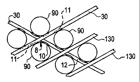
Fig. 2.
DESCRIPTION OF THE PREFERRED EMBODIMENTS
Referring now to the drawings, in which like reference numerals are used to
refer to the
same or functionally similar elements, Fig. 1 shows a nuclear steam generator
100 having a
series of lattice support bar arrays 120 at various points along its height
for supporting a plurality
of water tubes within the steam generator.
The lattice support bar arrays 120 have a peripheral ring 140 supporting a
series of high
and low bars 30, 130, respectively, as shown in Fig. 2. The high and low bars
30, 130 are
arranged parallel to one of two directions, with intersection angles of
60° and 120° where bars
30, 130 oriented in different directions cross each other.
Fig. 3 displays one end of a high bar 30 of the invention. The high bar 30 has
slotted
edge 40 and unslotted edge 50. A series of spaced apart slots 35, 135 are
formed extending from
the slotted edge 40 toward the unslotted edge 50. The slots 35, 135 are
provided at points where
intersections will be made with bars 30, 130 oriented in the opposite
direction in the bar array
120. The slots 35, 135 vary in length depending on which type of high or low
bar 30, 130 that

CA 02341292 2001-03-16
CASE 6052
-4-
the high bar 30 will intersect with. The slots are typically about 1 inch deep
for low bar 130
intersections and 1-%x inches deep for high bar 30 intersections.
In the spaces between each slot 35,135, a scalloped indentation 10 is formed
on each side
of the high bar 30. The indentations 10 of one side are longitudinally offset
from the
indentations 10 of the other side. The indentations are about 1-3/4 inches
long and extend from
the slotted edge 40.
The indentations 10 are formed extending from the same edge as the slots 35,
135. The
scalloped indentations 10 have arcuate cross sections, and a maximum depth of
not more than
one-half the thickness of the high bar 30. The width of the indentations 10 is
not more than the
diameter of the tubes used in the steam generator 100, and thus will typically
be about 5/8 to 7/8
inch wide. It is believed that the present invention will be most effective
when these parameters
are nearly equal to the half thickness and the tube diameter, respectively.
When the high bars 30 are used in the bar array 120, the scalloped
indentations align with
the tubes positioned between adjacent pairs of bars 30, 130. The scalloped
indentations 10 do
not contact the tubes 90, as shown in Fig. 4. The scalloped indentations 10
leave a tube contact
area 60 on the high bar 30 which is similar to that of the low bar 130, or
about 1-1/4 inches long.
Fig. 4 illustrates the use of high bars 30 having the scalloped indentations
10 in greater
detail. High bars 30 intersect with each other and low bars 130 in a section
of the bar array 120.
Tubes 90 are positioned in the spaces formed between the bars 30, 130 and
contact the bars 30,
ZO 130 for support.
One high bar 30 is oriented so that its indentations 11 are oriented opposite
the
indentations 10 of the other high bar 30. A small corner passage 8 is formed
by' the indentations
10, 11 at the 120° angle intersections between high bars 30. Since the
indentations 10, 11 are
longer than one-half the height of the high bars 30, they create a continuous
passage in the 120 °
angle corner. The corner passage 8 allows improved sweeping of flow through
the tube to bar
space and reduced potential for deposit buildup in the 120° angle
intersection corners.
The high bars 30 of the invention do not sacrifice structural strength, since
a full
thickness section 12 of the bar remains between each of the longitudinally
offset indentations 10
on each side of the high bar 30, and the bar 30 is full thickness above the
scalloped indentations
10.

CA 02341292 2001-03-16
CASE 6052
-5-
The scalloped indentations 10 could be formed by machining with a round nose
cutter,
machining with a radiused cutting wheel, rolling with a special setup at the
bar forming mill or
such as by pressing, coining or forging prior to slotting.
The indentations 10 provide a reduced tube contact area 60 without
substantially reducing
structural strength. The reduced contact area 60 results in less likelihood of
corrosion and
cracking, and limits the area in which such tube damage would occur. The
reduced area of likely
damage also reduces the potential volume of contaminated steam or water that
might be released
in event of a tube failure due to corrosion and cracking. Additionally, the
reduced contact length
60 reduces the length of tube for which eddy current inspection of the tube as
impeded by direct
contact with the bar.
While a specific embodiment of the invention has been shown and described in
detail to
illustrate the application of the principles of the invention, it will be
understood that the
invention may be embodied otherwise without departing from such principles.

Representative Drawing
A single figure which represents the drawing illustrating the invention.
Administrative Status

2024-08-01:As part of the Next Generation Patents (NGP) transition, the Canadian Patents Database (CPD) now contains a more detailed Event History, which replicates the Event Log of our new back-office solution.

Please note that "Inactive:" events refers to events no longer in use in our new back-office solution.

For a clearer understanding of the status of the application/patent presented on this page, the site Disclaimer , as well as the definitions for Patent , Event History , Maintenance Fee  and Payment History  should be consulted.

Event History

Description Date
Time Limit for Reversal Expired 2018-03-16
Change of Address or Method of Correspondence Request Received 2018-01-12
Letter Sent 2017-03-16
Inactive: IPC from MCD 2006-03-12
Grant by Issuance 2004-09-28
Inactive: Cover page published 2004-09-27
Amendment After Allowance Requirements Determined Compliant 2004-07-26
Letter Sent 2004-07-26
Inactive: Final fee received 2004-06-25
Pre-grant 2004-06-25
Amendment After Allowance (AAA) Received 2004-06-25
Letter Sent 2004-02-13
Notice of Allowance is Issued 2004-02-13
Inactive: Approved for allowance (AFA) 2004-01-28
Inactive: Cover page published 2001-09-25
Application Published (Open to Public Inspection) 2001-09-21
Inactive: First IPC assigned 2001-06-15
Inactive: Filing certificate - RFE (English) 2001-04-23
Filing Requirements Determined Compliant 2001-04-23
Letter Sent 2001-04-23
Application Received - Regular National 2001-04-23
Request for Examination Requirements Determined Compliant 2001-03-16
All Requirements for Examination Determined Compliant 2001-03-16

Abandonment History

There is no abandonment history.

Maintenance Fee

The last payment was received on 2004-03-01

Note : If the full payment has not been received on or before the date indicated, a further fee may be required which may be one of the following

  • the reinstatement fee;
  • the late payment fee; or
  • additional fee to reverse deemed expiry.

Please refer to the CIPO Patent Fees web page to see all current fee amounts.

Owners on Record

Note: Records showing the ownership history in alphabetical order.

Current Owners on Record
BABCOCK & WILCOX CANADA LTD.
Past Owners on Record
WILLIAM G. SCHNEIDER
Past Owners that do not appear in the "Owners on Record" listing will appear in other documentation within the application.
Documents

To view selected files, please enter reCAPTCHA code :


To view images, click a link in the Document Description column. To download the documents, select one or more checkboxes in the first column and then click the "Download Selected in PDF format (Zip Archive)" or the "Download Selected as Single PDF" button.

List of published and non-published patent-specific documents on the CPD .

If you have any difficulty accessing content, you can call the Client Service Centre at 1-866-997-1936 or send them an e-mail at CIPO Client Service Centre.


Document
Description 
Date
(yyyy-mm-dd) 
Number of pages   Size of Image (KB) 
Representative drawing 2001-09-11 1 10
Abstract 2001-03-16 1 22
Description 2001-03-16 5 215
Claims 2001-03-16 2 79
Drawings 2001-03-16 1 38
Cover Page 2001-09-25 1 42
Drawings 2004-06-25 1 30
Representative drawing 2004-08-25 1 11
Cover Page 2004-08-25 1 43
Courtesy - Certificate of registration (related document(s)) 2001-04-23 1 113
Filing Certificate (English) 2001-04-23 1 164
Reminder of maintenance fee due 2002-11-19 1 109
Commissioner's Notice - Application Found Allowable 2004-02-13 1 161
Maintenance Fee Notice 2017-04-27 1 178
Maintenance Fee Notice 2017-04-27 1 179
Fees 2003-03-04 1 32
Fees 2004-03-01 1 33
Correspondence 2004-06-25 3 97