Note: Descriptions are shown in the official language in which they were submitted.
CA 02341721 2004-10-18
-1-
ZOOM LAPAROSCOPE
BACKGROUND OF THE INVENTION
Endoscopes are devices which allow visual examination inside a hollow
cavity. In the field of medicine, the use of endoscopes permits inspection of
organs
for the purpose of diagnosis, viewing of a surgical site, sampling tissue, or
facilitating the safe manipulation of other surgical instruments. Laparoscopes
are
used particularly for examining organs in the abdominal area. Laparoscopes
_ typically include a light pipe for illuminating the region to be viewed, at
least one
lens assembly for focusing and relaying the image of the illuminated object,
and a
housing for the entire assembly which is structured to minimize tissue damage
during the surgical procedure. The light pipe can include a fiber optic
element for
illuminating the site. The laparoscope housing includes a distal section that
can be
inserted within a body cavity and a proximal section which can include a
handle that
a user grips to position the distal end near the surgical site.
CA 02341721 2001-02-26
WO 00/13568 PCT/US99/20640
-2-
Existing laparoscopes can include an imaging device such as a charge
coupled device (CCD). This solid state imaging system is used to capture an
image
of an object being viewed and convey it to a viewing device, such as monitor.
Currently, several problems exist with current laparoscope instruments. In
laparoscope devices without a zoom system, in order for the viewer to obtain a
closer view of an object, he has to adjust the position of the entire
laparoscope
manually. There is a risk of damaging or perforating soft tissues when the
laparoscope is moved at a surgical site. Laparoscope devices containing zoom
lenses also have drawbacks. After zooming on an object to be viewed, the user
must focus the lenses on the object to obtain a viewable image. A continuing
need
exists, therefore, for improvements in endoscopic design to provide safer,
more
economical, and effective systems for examination of patients.
SUMMARY OF THE INVENTION
The invention relates to an endoscope device, and in a preferred
embodiment, to a laparoscope having a tube with a proximal end and a distal
end
for insertion into body cavities or lumens for viewing of a site. The
laparoscope can
include, in a preferred embodiment, an illumination device, an imaging device,
and a
sheath having a lens system. The tube can comprise interlocking mechanisms to
connect the sheath to the proximal and distal portions of the tube.
In a preferred embodiment, the illumination device is a fiber optic coupler
and the imaging sensor can be a solid state imaging sensor, such as a charge
coupled
CA 02341721 2001-02-26
WO 00/13568 PCT/US99/20640
-3-
device or a two dimensional CMOS imaging device. The imaging device can be
positioned at the distal end tube adjacent to the sheath lens systems.
The laparoscope can also include, in another embodiment, a sheath having a
series of lenses that provides a zoom assembly. The laparoscope has a zoom
control
that actuates the zoom assembly. The zoom control can be mechanically
operated,
or in another embodiment, the zoom can be motorized. A finger operated switch
on
the handle can operate the motor or mechanically move the zoom assembly.
The front lens element on the sheath can be an objective lens which has a
dual purpose. First, it is used to image the surgical area with the required
resolution
onto the solid state imaging sensor. Second, it provides a hermetic seal at
the end of
the sheath. The hermetic seal provides a sterile environment for the
laparoscope. In
one embodiment, the front lens element is a diffractive lens. Most optical
systems
of existing laparoscopes use four to six lenses to image the surgical area
onto a
camera. Each lens surface reflects as much as 4% of the incident light
reaching the
lens surface. Because these losses are cumulative, a six element objective
lens can
lose as much as 36% of the light from an image. A diffractive lens system can
use
only one lens and can have a loss of only about 8% of the light from an image.
The sheath with the zoom assembly can comprise a plastic having an index
of refraction and an inner and outer layer of a lower index of refraction
plastic. The
sheath can also comprise a plurality of lenses as part of its zoom assembly.
In a
particular embodiment, 'there are four lenses in the optical system for the
zoom
assembly. In one aspect. of this embodiment of the invention, the sheath
includes a
moveable inner sleeve and a stationary inner sleeve as part of its zoom
assembly.
CA 02341721 2001-02-26
WO 00/13568 PCT/US99/20640
-4-
The second and fourth lenses are mounted to the moveable sleeve and the first
and
third lenses are mounted to the stationary sleeve. During a zooming procedure,
the
second and fourth lenses translate linearly while the third lens element is
caused to
rotate within its housing by a cam mechanism. An advantage of this apparatus
is
that it is not necessary to focus the lenses following actuation of the zoom
lens
assembly to adjust the magnification. Thus the image of a particular region of
interest can be magnified or demagnified to show a wider field of view without
adjusting the focus of the optical system.
In a preferred embodiment, the lenses can comprise a molded plastic
material. Existing laparoscopes incorporate expensive ground glass lenses in
structures that are complicated and difficult to manufacture. Because of this,
it has
not been possible to manufacture laparoscopes or laparoscope components
containing precision optics which are disposable and economically feasible for
the
user. Because the lenses of the present invention are plastic and relatively
inexpensive, the sheaths having the zoom lens assembly are disposable after a
single
procedure and thereby reduce the sterilization needs for the system.
The invention can also include a sheath for changing the angle of view of an
endoscope. The distal portion of the sheath can house the structure for
changing the
angle of view. In a preferred embodiment, this structure includes a prism.
Viewing
angles can be provided, preferably, between 30 and 45 degrees, however other
angles can be used.
In a preferred einbodiment, the laparoscope can include a handle at the
proximal end of the system which the user can grasp and manipulate with one
hand.
CA 02341721 2001-02-26
WO 00/13568 PCT/US99/20640
-5-
The handle can comprise two portions attached by a connector which
hermetically
seal the proximal end. The handle surface can also comprise a plurality of
surface
ridges and depressions. The handle allows the proximal end of a laparoscope to
remain sterile during a surgical procedure. The handle can be made from
plastic,
allowing for economic disposal after the laparoscopic procedure is completed.
The
connector can be disengaged using a push button manual release. The handle
permits one-handed use of the laparoscope, allowing the user a free hand to
perform
other tasks.
The invention further relates to a method of using a laparoscope and sheath
assembly. The method involves placing a sheath on a laparoscope, placing the
laparoscope within a surgical area, adjusting a zoom control to view an object
and
removing the laparoscope from the surgical area. The sheath can then be
removed
from the laparoscope and replaced with a sterile sheath. The method can then
be
repeated for a different patient while maintaining the sterility of the
instrument.
In another preferred embodiment of the invention the laparoscope tube and
the sheath can be flexible so that the user can orient the tube in a curved
shape to
afford viewing at a different angle. This embodiment can employ a distally
mounted
zoom assembly optically coupled to an imaging sensor as described previously
herein. The sheath and inner tube of the assembly are made with a flexible
henmetically sealed tubes having a shape memory so that the user can manually
manipulate the flexible section into the desired shape and insert the distal
end into a
bodily cavity without losing the shape. The system can also incorporate cable
or
CA 02341721 2001-02-26
WO 00/13568 PCT/US99/20640
-6-
other mechanical or motorized elements so that the user can reposition the
distal
flexible section while still within a cavity during a procedure.
BRIEF DESCRIPTION OF THE DRAWINGS
Figure 1 is an oithogonal view of one embodiment of a laparoscope with
sheath assembly in accordance with the invention.
Figure 2 is an orthogonal view of an embodiment of a laparoscope base unit.
Figure 3 is an orthogonal view of a laparoscope sheath.
Figure 4 is a lateral view of a lens series positioned in standard viewing
mode.
Figure 5 is a lateral view of a lens series positioned in full zoom mode.
Figure 6 shows a lateral cross-sectional view of an embodiment of the
laparoscope and sheath assembly with a zoom assembly.
Figure 7 shows a cross-sectional view of an embodiment of the laparoscope
and sheath assembly with a zoom assembly.
Figure 8 shows a. cross-sectional view of an embodiment of the laparoscope
and sheath assembly with a zoom assembly.
Figure 9 illustrates a cross-sectional view of an embodiment of a laparoscope
sheath having a prism mounted on its distal end.
Figure 10 illustrates a lateral view of an embodiment of the distal end of a
laparoscope.
Figure 11 shows a top view of an embodiment of the distal end of a
laparoscope.
CA 02341721 2001-02-26
WO 00/13568 PCT/US99/20640
-7-
Figure 12 shows a rear view of an embodiment of the distal end of a
laparoscope.
Figure 13 is a schematic representation of a method for using a laparoscope
and sheath assembly.
Figure 14 illustrates a flexible sheath laparoscopic system.
The foregoing and other objects, features and advantages of the invention
will be apparent from the following more particular description of preferred
embodiments of the invention, as illustrated in the accompanying drawings in
which
like reference characters refer to the same parts throughout the different
views. The
drawings are not necessarily to scale, emphasis instead being placed upon
illustrating the principles of the invention.
DETAILED DESCRIPTION OF THE INVENTION
A preferred embodiment of the invention is illustrated in Figure 1. A
laparoscope and sheath assembly 2 can be used, for example, in minimally
invasive
surgical procedures involving examination of the abdomen and abdominal organs.
The assembly 2 contains both a laparoscope base unit 6 and a laparoscope
sheath 4.
The laparoscope sheath 4 contains a zoom assembly, manipulated by a zoom
control
20, which allows a user to obtain an enlarged view of an object during a
laparoscopic surgical procedure without having to adjust the position of the
laparoscope inside the patient.
Figure 2 shows an embodiment of a laparoscope base unit 6 which includes a
probe or tube 14, a light source connector 8, an electrical source connector
10, an
CA 02341721 2001-02-26
WO 00/13568 PCT/US99/20640
-8-
illumination coupling device 18, a proximal interlocking device 12, a zoom
control
20, and an imaging device 16. The probe 14 of the laparoscope base unit 6
allows
viewing of the inside of a physiologic cavity. The probe 14 is hollow to allow
for
inclusion of an imaging device. The probe 14, in a preferred embodiment, is
composed of stainless steel. In an alternate embodiment, the probe 14 is
composed
of any biologically compatible and sterilizable material. The probe 14 is
elongated,
having a diameter in the: range between 6.8 mm and 7.2 mm and is between 350
mm
and 420 mm in length. In one example of a preferred embodiment, the length of
the
probe 14 can be 390 mni.
In one embodiment, the laparoscope base unit 6 contains both a light source
connector 8 to provide the laparoscope assembly 2 with light from an outside
source
and an electrical connector 10 which provides the laparoscope assembly 2 with
power from an extemal source. The light source connector 8 is located at the
proximal end of the laparoscope 6. In a preferred embodiment, the light source
connector 8 is mounted to the rear face 11 of the laparoscope 6 and is
parallel to the
probe 14 to allow for ease of handling the laparoscope assembly 2. In an
alternative
embodiment, the laparoscope assembly 2 can contain an internal lighting and
power
source. The illuminatior.i device 18 of the laparoscope base unit provides
light to the
distal end of the laparoscope and sheath assembly 2. The illumination device
18 is
coupled to the light source connector 8 at the proximal end of the laparoscope
and
sheath assembly 2. In a preferred embodiment, the illumination device 18 is a
fiber
optic annulus.
CA 02341721 2001-02-26
WO 00/13568 PCT/US99/20640
-9-
In one embodiinent, the proximal interlocking device 12 is located on the
laparoscope base unit 6 and secures the sheath 4 to the proximal end of the
base unit
6 to maintain its sterility. In a preferred embodiment, the interlocking
device 12 is a
split ring collar which surrounds the sheath and, when engaged, creates
pressure on
the sheath 4 without breaking the outer surface of the sheath 4. The
laparoscope
base unit 6 also contains a zoom control 20. The zoom control 20 allows the
user to
adjust the position of the tube 14 which is connected to a series of lenses,
thus
allowing the user to adjust the image of an object being viewed. In one
embodiment, the zoom control 20 is located at the proximal end of the
laparoscope
base unit 6 to allow easy access during a surgical procedure. In a preferred
embodiment, the zoom control 20 is operated manually as a sliding mechanism.
The
zoom contro120 has a range of motion sufficient to allow magnification and
demagnification of an object being viewed. In an alternate embodiment, a
rotating
mechanism can be used. In another embodiment, a motorized mechanism can
function as the zoom control 20.
The laparoscope base unit 6 contains an imaging device 16 connected to the
electrical source connector 10. The imaging device 16 includes a two
dimensional
solid state imaging sensor. In a preferred embodiment, the imaging device 16
is a
charge coupled device (CCD) camera. The CCD camera has a resolution of at
least
9 microns and provides high resolution visual detail of the surgical area
being
examined. In a preferred embodiment, the imaging device 16 is located at the
distal
end of the probe 14. Once the imaging device 16 is mounted at the distal end
of the
probe 14, the end can be; sealed by coupling an IR filter to the end of the
probe 14.
CA 02341721 2001-02-26
WO 00/13568 PCT/US99/20640
-10-
By positioning the imaging sensor at the distal end, this minimizes optical
losses in
the system and simplifies the optical design.
Figure 3 illustrates an embodiment of the laparoscope sheath 4. The sheath 4
comprises a center layer 22 and an inner 26 and outer 271ayer. The center
layer 22,
in a preferred embodiment, is composed of medium index of refraction plastic.
The
center layer 22 transmits light from the illumination device 18 located in the
proximal end of the laparoscope base unit 6 to the surgical area of interest.
The
center layer material is formed using co-extruded plastic technology to form a
light
rod 22. The light rod 22 is cut to a specific length with a tool designed to
create a
lens at each end of the rod 22. In a preferred embodiment, the rod 22 is
polyolefin.
The inner 26 and outer 27 layers of the sheath 4 are composed of low index of
refraction plastic. In a preferred embodiment, the inner 26 and outer 271ayers
can
be Teflon. Because the sheath is composed of one or more plastic materials the
sheath 4 is relatively inexpensive to replace and is therefore disposable. In
a
preferred embodiment, the sheath 4 comprises a proximal interlocking device 12
located at its proximal end 21 to allow a secure connection between the sheath
4 and
the laparoscope base unit 6. In this preferred embodiment, the proximal
interlocking
device 12 is also used to rotate the sheath 4 about its longitudinal axis 25.
In a preferred embodiment, the sheath 4 comprises an objective lens 24
hermetically sealed to its distal end. The objective lens 24 is preferably a
diffractive
lens element. The use of the diffractive lens element allows use of the
laparoscope
and sheath assembly 2 without an optical low pass filter. The diffractive
element
acts as a filtering component. The use of a diffractive lens element without
an
CA 02341721 2001-02-26
WO 00/13568 PCT/US99/20640
-11-
optical low pass filter allows the operator to more closely approach the
object being
viewed with the diffractive lens.
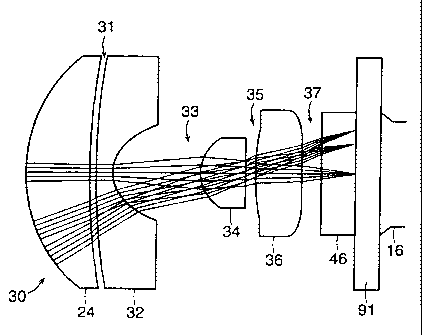
In a preferred embodiment, the sheath 4 contains a lens series 30. Figures 4
and 5 show an embodiment of four lenses. The lens series 30 includes an
objective
lens 24, a first lens spacing 31, a second lens element 32, a second lens
spacing 33, a
third lens element 34, a third lens spacing 35, a fourth lens element 36, and
a fourth
lens spacing 37. In a preferred embodiment, the second lens element 32 is a
zoom
element. In another preferred embodiment, the third lens element 34 and the
fourth
lens element 36 are aspheric lenses. The fourth lens element 36 is mounted
next to
an IR filter 46 which is adjacent an imaging device 16, both of which are
attached to
the laparoscope base unit 6. Figure 4 illustrates the lens series 30 arranged
to
provide a wide view of an object being observed. In this particular
arrangement, the
first lens spacing 31 is, for example, 0.1833 mm, the second lens spacing 33
is
2.5919 mm, the third lens spacing 35 is 0.070 mm and the fourth lens spacing
37 is
0.7532 mm. For this preferred embodiment, the lens series 30 as arranged can
provide between a 70 to 85 degree maximum field of view, with a preferred
field of
view of 72 degrees. Figure 5 illustrates the lens series 30 arranged to
provide a full
zoom view of an object being observed. In this particular arrangement, the
first lens
spacing 31 is 3.5546 mm, the second lens spacing 33 is 0.0595 mm, the third
lens
spacing 35 is 0.070 mm and the fourth lens spacing 37 is 2.7896 mm. In this
embodiment, the lens series 30 as arranged can provide between a 14 to 18
degree
minimum field of view, with a preferred field of view of 15.6 degrees. In
comparing
CA 02341721 2001-02-26
WO 00/13568 PCT/US99/20640
-12-
Figure 4 with Figure 5, the lens spacings 31, 33, 35 change when the lens
series 30
moves from a wide view arrangement to a full zoom arrangement.
Figures 4 and 5 also illustrate a ring 91. The ring 91 is attached to the
second 32 and fourth 36 lens elements of the lens series 30. The ring 91
allows the
second 32 and fourth 36 lens elements to be rotated within the sheath 4 by an
external mechanism. In. one embodiment, the external mechanism is a second
sheath
placed over the sheath 4 containing the lens series 30 and attached to the
ring 91.
Rotating the second sheath rotates the ring 91 which, in turn, rotates the
second 32
and fourth 361ens elements.
Figure 6 illustrates a cross-sectional view of the distal end of a laparoscope
and sheath assembly 2. Figure 6 shows the manner in which the lens series 30
is
mounted within the sheath 4 to form a zoom assembly 48. In a preferred
embodiment, the zoom assembly 48 contains the lenses 24, 32, 34, 36 of the
lens
series 30 having lens spacings 31, 33, 35, 37, respectively, a first sleeve
50, a second
sleeve 52, a second lens guide slot 571ocated in the surface of the first
sleeve 50,
and a third lens element housing 54 having a cam pin 59 which slides within a
cam
slot 58 located in the second sleeve 52.
The sheath 4 surrounding the laparoscope tube 14 can be a plastic
illumination element that is optically coupled to the annular array of fibers
or rod to
provide a light source for viewing at the distal end of the sheath 4.
The lenses of the lens series 30, in a preferred embodiment, are made from
optical grade polyurethane which reduces the weight of the lens series 30
within the
zoom assembly 48. The objective lens 24 is attached to the first sleeve 50,
located
CA 02341721 2001-02-26
WO 00/13568 PCT/US99/20640
-13-
on the inside surface of'the distal end of the sheath 4, with a hermetic seal.
In a
preferred embodiment of the invention, the objective lens 24 is attached to
the inner
surface of the distal end of the sheath 4 to form a hermetic seal. The
hermetic seal at
the distal end of the sheath 4 allows the laparoscope base unit 6 to remain
sterile
during a laparoscopic procedure.
The first sleeve 50, located at the distal end of the sheath 4, is connected
to
the objective lens 24 and the third lens element housing 54 containing the
third lens
element 34. The first sleeve 50, in a preferred embodiment, is stationary. A
second
sleeve 52 is also located at the distal end of the laparoscope sheath 4. The
second
lens element 32 and fourth lens element 36 are mounted on the second sleeve
52.
The second sleeve 52, in a preferred embodiment, is adjustable and is
connected to a
distal sheath interlocking mechanism 56 which is located on the end of the
laparoscope base unit 6.
The laparoscope 6 has an angle guide 65 and arms 60 as part of the distal
sheath interlocking mechanism 56, located at the distal end of the laparoscope
6.
Once the laparoscope sheath 4 is placed over the laparoscope 6, the angle
guide 65
and arms 60 aid in properly orienting and locking the sheath 4 onto the
laparoscope
6. The angle guide 65 comprises a slot in the laparoscope 6 to receive the
proximal
end of the second sleeve 52 of the laparoscope sheath 4 and maneuvers the
second
sleeve 52 into a locking position. The arms 60 extend laterally on opposite
sides of
the distal end of the laparoscope 6. The proximal end of the second sleeve 52
contains locking slots for engaging the arms 60 and locking the distal end of
the
sheath 4 to the laparoscope 6. The proximal end of the second sheath 52 slides
and
CA 02341721 2001-02-26
WO 00/13568 PCT/US99/20640
-14-
"snap" fits over the arms 60, thus securing the distal end of the sheath 4
onto the
laparoscope. The arms are preferably spring loaded, allowing for easy
installation
and removal of the sheath 4. In this embodiment, the arms 60 can be released
by the
user with a switch at the proximal end.
The zoom assembly 48 is adjusted by the zoom control 20 located at the
proximal end of the laparoscope base unit 6. The zoom control is in contact
with the
tube 14 of the laparoscope base unit 6. Activation of the zoom control 20
causes the
tube 14 to translate. Because the second sleeve 52 is coupled to the distal
end of the
tube 14, any motion of the tube 14 causes the second sleeve 52 to translate
along the
long axis of the laparoscope and sheath assembly 2. This motion, in turn,
causes the
second lens element 32 and the fourth lens element 36 to translate. During the
zooming procedure, the third lens element 34 is forced to rotate within its
housing
54. The cam slot 58, located in the second sheath 52, drags the cain pin 59
which is
mounted in the cam slot 58 and connected to the third lens element 34. By
virtue of
the shape of the cam slot 58, the third lens element 34 rotates during a
zooming
procedure.
Allowing the second 32 and fourth 36 lens elements to translate and the third
lens element 34 to rotate during a zooming procedure circumvents the necessity
of
the user to further focus the lenses of the lens series 30 once the procedure
is
complete. The zoom assembly 48 retains its focus whether in full view mode or
full
zoom mode. In a preferred embodiment, the zoom assembly 48 travels between 5
mm and 10 mm over the full zoom range during a zooming procedure.
CA 02341721 2007-01-04
-15-
Figure 7 shows a cross-sectional view of the distal end of a laparoscope and
sheath assembly 2, rotated 180 degrees from the view shown in Figure 6. The
zoom
assembly 48 contains the lenses 24, 32, 34, 36 of the lens series 30 having
lens
spacings :31, 33, 35, 37, a first sleeve 50, a second sleeve 52, and a third
lens element
housing 54 mounted. The first sleeve 50 comprises the first 24 and third 34
lens
elements and is located within the distal end of the laparoscope sheath 4. The
second sleeve 52 comprises the second 32 and fourth 36 lens elements and is
connected to a distal sheath interlocking mechanism 56, located on the distal
end of
the laparoscope base unit 6.
Figure 8 illustrates a front view of the arrangement of the sheath 4 and the
laparoscope base unit 6 when assembled as a laparoscope and sheath assembly 2.
The assembly 2, as illustrated, comprises a laparoscope base unit 6 having a
probe or
tube 14, an imaging device 16, and a distal sheath interlocking mechanism 56.
The
assembly :2 also comprises a sheath 4 composed of a light rod 22 with an outer
26
and an inner 27 sheath coating and having an objective lens 24, a first sleeve
50, a
second sleeve 52, and a guide slot 57.
Figure 9 shows an altemate embodiment for a laparoscope sheath 97. In this
embodiment, the laparoscope sheath 97 comprises a prism 92 mounted to its
distal
end and a.rotational adjustment 93. The prism face 90, in a preferred
embodiment,
is angled between 22.5 and 45 degrees relative to longitudinal axis 95. When
rotated about the longitudinal axis 95, the prism 92 provides the user with a
360
degree view of the surgical area being examined. In one embodiment, the user
can
rotate the laparoscope and sheath assembly 2 manually to obtain the 360 degree
CA 02341721 2001-02-26
WO 00/13568 PCT/US99/20640
-16-
view. A rotational adjustment 93, however, can be used to rotate the prism
sheath
97 about the axis 95. 7'he rotational adjustment 93 can be located at the
proximal
end of the sheath 97 and, in a preferred embodiment, the rotational adjustment
93 is
positioned so as to allow the user easy access, by means of the user's thumb
or
fingers, when operated using a one-handed method.
The sheath 97 is attached to the laparoscope 6 by a ring 91 which can rotate
around the axis 95 of the laparoscope 6. The ring 91 is connected to the
second 32
and fourth 36 lens elements of the lens series 30. When the sheath 97 is
rotated by
the user, the ring 91 causes the second 32 and fourth 36 lens elements to
rotate.
The prism sheath 97, as illustrated in Figure 9, fits over a laparoscope
sheath
having a zoom assembly 48. In this embodiment of the invention, the sheath 97
can
be composed from a light pipe 96 to allow illumination of the area being
examined.
In an alternate embodinient, the prism 92 can be directly attached to a
laparoscope
sheath having a zoom lens assembly 48. A single sheath combining both the
prism
92 and the zoom lens assembly 48 can be used rather than using two separate
sheaths. A rotational element 93 can still be used to rotate the prism 92 to
obtain a
360 degree view of the area being examined. Similarly, the sheath is attached
to a
ring 91 which causes the second 32 and fourth 36 lens elements of the lens
series 30
to rotate with the prism 92.
Figures 10, 11 and 12 show a lateral, overhead, and rear view, respectively,
of the proximal end of a laparoscope and sheath assembly 2. In one embodiment,
the proximal end of the assembly 2 contains a handle 70, an electrical
connector 10,
CA 02341721 2001-02-26
WO 00/13568 PCT/US99/20640
-17-
an illumination connector 8, a fiber optic coupling, a zoom adjustment, and a
proximal interlocking device 12 .
One purpose of'the handle 70 is to maintain the sterility of the proximal end
of the laparoscope base; unit 6. In one embodiment, the handle 70 is
disposable. The
handle 70 preferably comprises a right handle portion 86 and a left handle
portion
88. These portions 86, 88 are joined by a connector device 77. In one
embodiment,
the connector device 77 is a mechanical connector triggered by an external
control
78. Another purpose of the handle 70 is to provide ease of use of the
laparoscope.
The handle can have a knife shaped handle surface 82 in one embodiment. This
surface 82 allows the user to easily grasp the laparoscope in using either his
right or
left hand. The surface 82 also allows users with varying hand sizes to
comfortable
grip the laparoscope.
The fiber optic coupling 79 connects the illumination connector 8 to the
illumination device 18 of the laparoscope base unit 6. The fiber optic
coupling 79 is
mounted within the handle 70 to accommodate rotational motion of the coupling
79
in conjunction with rotation of element 12.
A zoom control 20 is mounted to the handle 70 and connected to the lens
system in the laparoscope tube 14. The zoom lens contro120 is a sliding-type
control and is shaped so that a user may easily and one-handedly manipulate
the
control 20 with his thumb or other digits. In a preferred embodiment, there is
a 5
mm total travel distance possible for the zoom control.
The proximal end of the laparoscope and sheath assembly 6 also contains an
interlocking device 12. In a preferred embodiment, the interlocking device 12
is a
CA 02341721 2007-01-04
-18-
collar which surrounds the sheath and, when engaged, creates pressure on the
sheath
4 withoi.rt breaking into the outer surface. The interlocking device 12, in a
preferred
embodiment, can be secured and loosened by a user utilizing only one hand.
Figure 13 illustrates a schematic representation of a method for using a
laparoscope and sheath assembly. The user places and secures a sterile sheath
on the laparoscope 102. The sheath covers the tube of the laparoscope and
conlnects
to the laparoscope at both its distal and proximal ends. A pin and an angled
pin
guide are located at the distal end of the laparoscope. These devices force
the sheath
into a particular orientation on the laparoscope and secure the sheath to the
distal
end of the tube. A locking mechanism connects the sheath to the proximal end
of
the laparoscope. A surgical area is prepared for a laparoscopic procedure by
the user
104. The user inserts the laparoscope with sheath assembly into a surgical
area 106.
The laparoscope provides the user with a minimally invasive view of a
physiologic
cavity. The surgical area can then be viewed using the laparoscope and sheath
assembly. An imaging sensor is used to provide the image from the surgical
area to
a display device for viewing 108 by the user. Depending on the type of sheath
used,
the user can either zoom on an object being viewed I 10 or obtain a 360 degree
view
of the object by rotating the sheath 112. Once the surgical procedure is
completed, the
laparoscope and sheath assembly is removed from the surgical area 114. The
sheath
can then be removed from the laparoscope 116. If the laparoscope is needed for
another surgical procedure, a new sterile sheath can be placed and secured on
the
laparoscope 118. The laparoscope and sheath assembly can then be inserted into
the
surgical area of a different patient 120. By using a new sterile sheath for
each
CA 02341721 2001-02-26
WO 00/13568 PCT/US99/20640
-19-
procedure, the laparoscope unit does not have to be sterilized after each
operation if
contamination is limited. This method can be repeated for subsequent patients
while
maintaining the sterility of the laparoscope unit.
In another embodiment, the zoom lens assembly, the prism, or both can be
mounted within a non-disposable, reusable housing rather than in a single
disposable
or multiple disposable sheaths. A non-disposable and reusable housing requires
that
the housing be sterilized between uses. In a preferred embodiment, the housing
is
stainless steel.
In another preferred embodiment of the invention, the laparoscope 140
includes a flexible probe 144 and a flexible sheath 146 extending over the
flexible
tube. This embodiment is illustrated in Figure 14. The laparoscope probe or
tube
144 can have a flexible outer surface that retains the described shape. Both
the tube
144 and the sheath 146 can have a flexible region 142 which the user can
manually
manipulate to achieve a desired shape. The tube 144 can be an accordion type
cover
to provide flexibility and the sheath 146 can be formed with a material having
shape
memory such that the user can bend the structure to have a particular angular
shape
for viewing of sites within a body at different angles. Mechanical cables of
other
mechanical elements can also be used to manually manipulate the angular
orientation of the tube. A flexible extruded plastic can be used to couple
light from
the source to the distal end of the device. In a preferred embodiment, the
flexible
tube 144 is optically transmissive polyurethane, manufactured by Hercules
Corporation, Wilmington, DE. The flexible system can also use a two
dimensional
solid state sensor array at the distal end of the probe and a zoom assembly at
the
CA 02341721 2001-02-26
WO 00/13568 PCT/US99/20640
-20-
distal end of the sheath. The flexible system can also employ the optical and
mechanical coupling features described previously in the application. The
handle
148 can be the two piece disposable assembly described previously herein.
Alternatively, the flexible system can be a non-disposable system that is
reused after each procedure following sterilization.
While this invention has been particularly shown and described with
references to preferred embodiments thereof, it will be understood by those
skilled
in the art that various changes in form and details may be made therein
without
departing from the spirit and scope of the invention as defined by the
appended
claims.