Language selection

Search

Patent 2341844 Summary

Third-party information liability

Some of the information on this Web page has been provided by external sources. The Government of Canada is not responsible for the accuracy, reliability or currency of the information supplied by external sources. Users wishing to rely upon this information should consult directly with the source of the information. Content provided by external sources is not subject to official languages, privacy and accessibility requirements.

Claims and Abstract availability

Any discrepancies in the text and image of the Claims and Abstract are due to differing posting times. Text of the Claims and Abstract are posted:

  • At the time the application is open to public inspection;
  • At the time of issue of the patent (grant).
(12) Patent: (11) CA 2341844
(54) English Title: GAS TURBINE COMBUSTOR
(54) French Title: CHAMBRE DE COMBUSTION DE TURBINE A GAZ
Status: Expired and beyond the Period of Reversal
Bibliographic Data
(51) International Patent Classification (IPC):
  • F23R 03/28 (2006.01)
  • F23R 03/34 (2006.01)
(72) Inventors :
  • NISHIDA, KOICHI (Japan)
  • TANAKA, KATSUNORI (Japan)
  • MANDAI, SHIGEMI (Japan)
  • KAWATA, YUTAKA (Japan)
  • OHTA, MASATAKA (Japan)
(73) Owners :
  • MITSUBISHI HITACHI POWER SYSTEMS, LTD.
(71) Applicants :
  • MITSUBISHI HITACHI POWER SYSTEMS, LTD. (Japan)
(74) Agent: NORTON ROSE FULBRIGHT CANADA LLP/S.E.N.C.R.L., S.R.L.
(74) Associate agent:
(45) Issued: 2005-03-15
(22) Filed Date: 2001-03-21
(41) Open to Public Inspection: 2001-11-19
Examination requested: 2001-03-21
Availability of licence: N/A
Dedicated to the Public: N/A
(25) Language of filing: English

Patent Cooperation Treaty (PCT): No

(30) Application Priority Data:
Application No. Country/Territory Date
2000-147241 (Japan) 2000-05-19

Abstracts

English Abstract

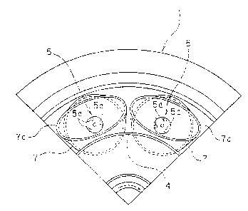
To present a gas turbine combustor capable of improving the fuel distribution from the main fuel nozzle, suppressing fluctuations of internal pressure and elevation of inner tube metal temperature, and enhancing the combustion stability and durability of the combustor. A gas turbine combustor used in a gas turbine having a multi-nozzle type premixing combustor with a nozzle outer tube (7) for forming and injecting a premixed gas of main fuel and combustion air divided and disposed in plural sections around a cone (4) for forming a diffusion flame by reaction between pilot fuel and combustion air disposed in a center of a section of a combustor inner tube (1), in which nozzle holes (5a) of a main fuel nozzle (5) are formed in three positions at equal intervals on the nozzle main body wall, and one of them is disposed at the outer periphery of the combustor inner tube (1) on the diametral line linking between the center of the combustor inner tube (1) and the center of the main fuel nozzle (5), and the fuel distribution to the outer periphery is decreased.


French Abstract

Présentation d'une chambre de combustion de turbine à gaz capable d'améliorer la distribution du combustible provenant de la buse pour combustible principal, de supprimer les fluctuations de pression interne et d'élévation de la température du métal du tube intérieur, et d'améliorer la stabilité à la combustion et la durabilité de la chambre de combustion. Une chambre de combustion de turbine à gaz utilisée dans une turbine à gaz possédant une chambre de combustion à prémélange du type à plusieurs buses présentant un tube extérieur (7) de buse pour la formation et l'injection d'un gaz prémélangé constitué d'un combustible principal et d'air de combustion divisé et disposé en plusieurs sections autour d'un cône (4) pour former une flamme de diffusion par réaction entre du combustible pilote et de l'air de combustion disposée au centre d'une section d'un tube intérieur de la chambre de combustion (1) où des orifices (5a) d'une buse (5) pour combustible principal sont formés dans trois positions à intervalles équidistants sur la paroi du corps principal de buse, et l'un d'entre eux est disposé sur la périphérie extérieure du tube intérieur (1) de la chambre de combustion sur la ligne de diamètre reliant le centre du tube intérieur (1) de la chambre de combustion et le centre de la buse (5) pour combustible principal, et la distribution du combustible vers la périphérie extérieure est réduite.

Claims

Note: Claims are shown in the official language in which they were submitted.


What is claimed is:
1. A gas turbine combustor used in a gas turbine having a
multi-nozzle type premixing combustor with a nozzle outer tube
for forming and injecting a premixed gas of main fuel and
combustion air divided and disposed in plural sections around
a cone for forming a diffusion flame by reaction between pilot
fuel from a pilot fuel nozzle and combustion air disposed in a
center of a section of a combustor inner tube, wherein nozzle
holes of a plurality of main fuel nozzles disposed about the
pilot fuel nozzle for injecting the main fuel are opened and
formed more at the inner side than at the outer periphery of
the combustor inner tube in the nozzle main body wall, so that
the fuel distribution to the outer periphery is decreased.
2. The gas turbine combustor according to claim 1, wherein
said nozzle holes are formed in odd- number positions at
nearly equal intervals on the nozzle main body wall, and one
of them is disposed at the outer periphery of the combustor
inner tube on the diametral line linking between the center of
the combustor inner tube and the center of the main fuel
nozzle.
3. The gas turbine combustor according to claim 2, wherein
said nozzle holes are formed in three positions at nearly
equal intervals on the nozzle main body wall, and one of them
is disposed at the outer periphery of the combustor inner tube
on the diametral line linking between the center of the
combustor inner tube and the center of the main fuel nozzle.
7

Description

Note: Descriptions are shown in the official language in which they were submitted.


CA 02341844 2001-03-21
GAS TURBINE COMBUSTOR
BACKGROUND OF THE INVENTION
Field of the Invention
The present invention relates to a gas turbine combustor,
and more particularly to a multi-nozzle type premixing
combustor.
Description of the Related Art
Recently, the gas turbine combustor, for example, the
steam cooling type combustor capable bf realizing low NOx even
in the gas turbine of 1500° C class is attracting a wide attention.
That is, by cooling the combustor wall by steam, the air hitherto
used for cooling of wall can be used for combustion, and the
premixed combustion temperature is suppressed to a level of
air-cooled combustor in spite of temperature elevation in the
gas turbine, sot that low NoX is realized.
As such steam cooled combustor, a conventional example
of multi-nozzle type premixing combustor as shown in Fig. 5 is
known, in which a nozzle outer tube 7 for forming and injecting
a premixed gas of main fuel from a main fuel nozzle 5 and
combustion air from main swirler 6 is divided and disposed in
plural sections around a cone 4 for forming a diffusion flame
by reaction between the pilot fuel from a pilot fuel nozzle 2
and combustion air from a pilot swirler 3, being disposed in
the center of the section of a combustor inner tube 1.
In the main fuel nozzle 5, as shown in Fig. 4, the fuel
is injected from plural nozzle holes 5a (about 1.0 mm in
1

CA 02341844 2001-03-21
diameter) opened in the nozzle main body wall, and is mixed with
the air flowing in the nozzle outer tube through the main swirler
6, thereby forming a premixed gas.
In Fig. 4 and Fig. 5, the arrow shows the flow of fuel
and air.
However, in such conventional multi-nozzle type
premixing combustor, as shown in Fig. 3, since the nozzles holes
5a of the main fuel nozzle 5 are formed in three positions on
the outer periphery of the combustor inner tube 1 and in two
positions at the inner side, the fuel distribution to the outer
periphery increases , and it may bounce on an elliptical extended
pipe 7a (which is provided for preventing back-fire by raising
the gas flow velocity) due to circumferential flow by swirl flow
by swirler, and may collide against the wall of the combustor
inner tube 1 (see arrow in Fig. 3).
As a result, fuel liquid drops may deposit on the wall
of the combustor inner tube 1 ( see hatching ( b ) in Fig . 3 ) , and
internal pressure fluctuates to spoil combustion stability, or
the metal temperature is raised by self-ignition, thereby
breaking the wall of the combustor inner tube 1 ( see broken part
(a) in Fig. 3).
SUI~tARY OF THE INVENTION
The invention is devised in the light of such background,
and it is hence an object thereof to present a gas turbine
combustor capable of improving fuel distribution from main fuel
nozzle, suppressing internal pressure fluctuation and
2

CA 02341844 2001-03-21
elevation of inner tube metal temperature, and realizing
combustion stability and improvement of durability of
combustor.
To achieve the object, the gas turbine combustor of the
invention is a gas turbine combustor used in a gas turbine having
a multi-nozzle type premixing combustor with a nozzle outer tube
for forming and injecting a premixed gas of main fuel and
combustion air divided and disposed in plural sections around
a cone for forming a diffusion flame by reaction between pilot
fuel and combustion air disposed in a center of a section of
a combustor inner tube, in which nozzle holes of a main fuel
nozzle for injecting the main fuel are opened and formed more
at the inner side than at the outer periphery of the combustor
inner tube in the nozzle main body wall, and the fuel
distribution to the outer periphery is decreased.
BRIEF DESCRIPTION OF THE DRAWINGS
Fig. 1 is an essential front view of a gas turbine
combustor showing an embodiment of the invention;
Fig. 2 is a side sectional view of its main fuel nozzle;
Fig. 3 is an essential front view of a conventional gas
turbine combustor;
Fig. 4 is a side sectional view of its main fuel nozzle;
and
Fig. 5 is a general structural view of a multi-nozzle type
premixing combustor thereof.
3

CA 02341844 2001-03-21
DETAILED DESCRIOTION OF THE PREFERRED EMBODIMENT
A gas turbine combustor of the invention is described
below by referring to a preferred embodiment thereof taken in
conjunction with the accompanying drawings.
Fig. 1 is an essential front view of a gas turbine
combustor showing an embodiment of the invention, and Fig. 2
is a side sectional view of its main fuel nozzle. The entire
structure of the combustor is shown in Fig. 5, and detailed
description is omitted.
As shown in Fig. 2, a main fuel nozzle 5 is disposed in
the center of the section of a nozzle outer tube 7, and a main
swirler 6 is disposed in a peripheral gap between the nozzle
main body outer periphery of this main fuel nozzle 5 and the
inner periphery of the nozzle outer tube 7, and so far the
structure is same as shown in Fig. 4.
In this embodiment , as shown in Fig . 1, in the main fuel
nozzle 5, the fuel is injected from three nozzle holes 5a ( about
1. 3 mm in diameter in this embodiment ) opened in the nozzle main
body wall, and is mixed with the air flowing around the nozzle
outer periphery through the main swirler 6 , so that a premixed
gas is formed .
In the shown example, the three nozzle holes 5a are
disposed at intervals of 120 degrees, and one of them is disposed
at t he outer side of the combustor inner tube 1 on a diametral
line linking the center of the combustor inner tube 1 and the
center of the main fuel nozzle 5. These nozzle holes 5a are
opened at an inclination of about 20 degrees to the downstream
4

CA 02341844 2001-03-21
side of the gas flow.
Having such configuration, in the main fuel nozzle 5, one
nozzle hole 5a is disposed at the outer side of the combustor
inner tube l, and two at the inner side, so that the fuel
distribution to the outer side is decreased from that of the
inner side.
Accordingly, a swirl flow of a favorably mixed premixed
gas is obtained, thereby suppressing collision against the wall
of the combustor inner tube 1 of the flammable premixed gas due
to bouncing on the elliptical extended~pipe 7a by the peripheral
flow of swirl flow of the main swirler 6 as experienced in the
prior art.
As a result, a stable combustion state is obtained,
thereby avoiding loss of combustion stability due to fuel liquid
drops sticking to the wall surface of the combustor inner tube
1 to induce internal pressure fluctuations or burning of wall
of the combustor inner tube 1 due to elevation of metal
temperature by self-ignition.
The invention is not limited to the illustrated
embodiment alone, but may be changed and modified in the number
of nozzle holes, opening positions, and others so far as not
departing from the true spirit of the invention.
As described specifically in the embodiment, the
invention according to a first aspect is a gas turbine combustor
used in a gas turbine having a multi-nozzle type premixing
combustor with a nozzle outer tube for forming and injecting
a premixed gas of main fuel and combustion air divided and

CA 02341844 2001-03-21
disposed in plural sections around a cone for forming a diffusion
flame by reaction between pilot fuel and combustion air disposed
in a center of a section of a combustor inner tube, in which
nozzle holes of a main fuel nozzle for in jecting the main fuel
are opened and formed more at the inner side than at the outer
periphery of the combustor inner tube in the nozzle main body
wall, and the fuel distribution to the outer periphery is
decreased, and therefore the fuel distribution from the main
fuel nozzle is improved, fluctuations of internal pressure and
elevation of inner tube metal temperature are suppressed, and
hence the combustion stability and durability of the combustor
are enhanced.
Further, in the invention according to a second aspect,
the nozzle holes are formed in three positions at equal intervals
on the nozzle main body wall, and one of them is disposed at
the outer periphery of the combustor inner tube on the diametral
line linking between the center of the combustor inner tube and
the center of the main fuel nozzle, and therefore the same effect
and action as in the invention according to a first aspect are
obtained.
6

Representative Drawing
A single figure which represents the drawing illustrating the invention.
Administrative Status

2024-08-01:As part of the Next Generation Patents (NGP) transition, the Canadian Patents Database (CPD) now contains a more detailed Event History, which replicates the Event Log of our new back-office solution.

Please note that "Inactive:" events refers to events no longer in use in our new back-office solution.

For a clearer understanding of the status of the application/patent presented on this page, the site Disclaimer , as well as the definitions for Patent , Event History , Maintenance Fee  and Payment History  should be consulted.

Event History

Description Date
Time Limit for Reversal Expired 2017-03-21
Letter Sent 2016-03-21
Letter Sent 2015-03-26
Inactive: IPC from MCD 2006-03-12
Grant by Issuance 2005-03-15
Inactive: Cover page published 2005-03-14
Pre-grant 2004-12-09
Inactive: Final fee received 2004-12-09
Notice of Allowance is Issued 2004-10-12
Letter Sent 2004-10-12
Notice of Allowance is Issued 2004-10-12
Inactive: Approved for allowance (AFA) 2004-09-30
Amendment Received - Voluntary Amendment 2004-07-02
Inactive: S.30(2) Rules - Examiner requisition 2004-01-29
Application Published (Open to Public Inspection) 2001-11-19
Inactive: Cover page published 2001-11-18
Inactive: Filing certificate - RFE (English) 2001-08-17
Inactive: First IPC assigned 2001-06-15
Letter Sent 2001-06-06
Inactive: Filing certificate correction 2001-05-14
Inactive: Single transfer 2001-05-14
Inactive: Courtesy letter - Evidence 2001-05-01
Inactive: Filing certificate - RFE (English) 2001-04-25
Application Received - Regular National 2001-04-25
Request for Examination Requirements Determined Compliant 2001-03-21
All Requirements for Examination Determined Compliant 2001-03-21

Abandonment History

There is no abandonment history.

Maintenance Fee

The last payment was received on 2005-01-17

Note : If the full payment has not been received on or before the date indicated, a further fee may be required which may be one of the following

  • the reinstatement fee;
  • the late payment fee; or
  • additional fee to reverse deemed expiry.

Patent fees are adjusted on the 1st of January every year. The amounts above are the current amounts if received by December 31 of the current year.
Please refer to the CIPO Patent Fees web page to see all current fee amounts.

Owners on Record

Note: Records showing the ownership history in alphabetical order.

Current Owners on Record
MITSUBISHI HITACHI POWER SYSTEMS, LTD.
Past Owners on Record
KATSUNORI TANAKA
KOICHI NISHIDA
MASATAKA OHTA
SHIGEMI MANDAI
YUTAKA KAWATA
Past Owners that do not appear in the "Owners on Record" listing will appear in other documentation within the application.
Documents

To view selected files, please enter reCAPTCHA code :


To view images, click a link in the Document Description column. To download the documents, select one or more checkboxes in the first column and then click the "Download Selected in PDF format (Zip Archive)" or the "Download Selected as Single PDF" button.

List of published and non-published patent-specific documents on the CPD .

If you have any difficulty accessing content, you can call the Client Service Centre at 1-866-997-1936 or send them an e-mail at CIPO Client Service Centre.


Document
Description 
Date
(yyyy-mm-dd) 
Number of pages   Size of Image (KB) 
Representative drawing 2001-10-23 1 12
Abstract 2001-03-20 1 30
Description 2001-03-20 6 220
Claims 2001-03-20 1 38
Drawings 2001-03-20 4 51
Claims 2004-07-01 1 34
Filing Certificate (English) 2001-04-24 1 164
Courtesy - Certificate of registration (related document(s)) 2001-06-05 1 113
Filing Certificate (English) 2001-08-16 1 175
Reminder of maintenance fee due 2002-11-24 1 106
Commissioner's Notice - Application Found Allowable 2004-10-11 1 160
Maintenance Fee Notice 2016-05-01 1 170
Correspondence 2001-04-24 1 24
Correspondence 2001-05-13 2 109
Correspondence 2004-12-08 1 31