Language selection

Search

Patent 2342032 Summary

Third-party information liability

Some of the information on this Web page has been provided by external sources. The Government of Canada is not responsible for the accuracy, reliability or currency of the information supplied by external sources. Users wishing to rely upon this information should consult directly with the source of the information. Content provided by external sources is not subject to official languages, privacy and accessibility requirements.

Claims and Abstract availability

Any discrepancies in the text and image of the Claims and Abstract are due to differing posting times. Text of the Claims and Abstract are posted:

  • At the time the application is open to public inspection;
  • At the time of issue of the patent (grant).
(12) Patent: (11) CA 2342032
(54) English Title: YARN CARRIER HAVING AN ANNULAR RECESS CONTAINING MARKINGS FOR YARN IDENTIFICATION
(54) French Title: TRANSPORTEUR DE FILS MUNI D'UNE ENTAILLE ANNULAIRE AYANT DES MARQUES POUR L'IDENTIFICATION DES FILS
Status: Expired and beyond the Period of Reversal
Bibliographic Data
(51) International Patent Classification (IPC):
  • B65H 75/10 (2006.01)
  • B65H 75/18 (2006.01)
  • B65H 75/28 (2006.01)
(72) Inventors :
  • AUTEN, JOHN F. (United States of America)
(73) Owners :
  • SONOCO DEVELOPMENT, INC.
(71) Applicants :
  • SONOCO DEVELOPMENT, INC. (United States of America)
(74) Agent: MCCARTHY TETRAULT LLP
(74) Associate agent:
(45) Issued: 2009-05-26
(22) Filed Date: 2001-03-23
(41) Open to Public Inspection: 2001-09-28
Examination requested: 2005-10-13
Availability of licence: N/A
Dedicated to the Public: N/A
(25) Language of filing: English

Patent Cooperation Treaty (PCT): No

(30) Application Priority Data:
Application No. Country/Territory Date
09/536,132 (United States of America) 2000-03-28

Abstracts

English Abstract

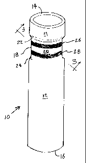
A re-usable yarn carrier having an annular recess containing markings for yarn identification is disclosed. The carrier comprises a tube having a pair of spaced apart ends and an outer peripheral surface located between the ends. An annular recess is formed in the outer peripheral surface adjacent one end of the tube. The annular recess defines a marking surface located radially inward from the outer peripheral surface. The marking surface includes markings, for example, colored bands, bar code or the like, for identifying at least one characteristic of the yarn wound onto the carrier. Placing the markings in the recess prevents them from being worn off through frictional contact with the drive mechanism that rotates the carrier during the winding operation, winding of the first layer of yarn onto the carrier, handling of the carrier while empty or the like. The marking surface may further include a yarn catching means, for example a knurled surface, slip-resistant coating, hooks or the like, for catching the yarn at the start of the winding operation.


French Abstract

Un transporteur de fils réutilisable muni d'une entaille annulaire ayant des marques pour l'identification des fils est décrit. Le transporteur comprend un tube ayant une paire d'extrémités espacées et une surface périphérique extérieure située entre les extrémités. Une entaille annulaire est formée dans la surface périphérique extérieure adjacente à une extrémité du tube. L'entaille annulaire définit une surface de marquage située radialement vers l'intérieur depuis la surface périphérique extérieure. La surface de marquage comprend le marquage, par exemple, des bandes de couleur, des codes à barres ou une marque similaire, pour identifier au moins une caractéristique du fil enroulé sur le transporteur. Placer les marquages dans l'entaille les empêche d'être usés par contact de friction avec le mécanisme d'entraînement qui fait tourner le transporteur lors de l'opération d'enroulement, l'enroulement de la première couche de fils sur le transporteur, la manipulation du transporteur à vide ou toute autre opération similaire. La surface de marquage peut en outre comprendre un moyen d'accrochage de fil, par exemple une surface moletée, un revêtement résistant au glissement de revêtement, des crochets ou un dispositif similaire, pour attraper le fil au début de l'opération d'enroulement.

Claims

Note: Claims are shown in the official language in which they were submitted.


-7-
Claims
What is claimed is:
1. A yarn carrier adapted to be mounted on a winding machine, to have yarn
wound
thereon and unwound therefrom, and to form a yarn package, the yarn carrier
comprising:
a tube, the tube having a first end, a second end and an outer peripheral
surface
located between the first and second end, the tube including a recess formed
in the outer
peripheral surface, the recess defining a marking surface located radially
inward from the
outer peripheral surface; and
at least one marking disposed on the marking surface, the marking adapted to
identify
at least one characteristic of the yarn wound onto the carrier, the at least
one marking having
at least one exposed surface, all of the exposed surfaces of the at least one
marking being
located radially inward from the outer peripheral surface.
2. The yarn carrier of claim 1 wherein the recess is continuous around the
outer
peripheral surface of the carrier.
3. The yarn carrier of claim 2 wherein the tube is cylindrical and the recess
is annular in
shape.
4. The yarn carrier of claim 2 wherein the marking comprises a colored band
extending
around the periphery of the marking surface.
5. The yarn carrier of claim 2 wherein the markings comprise two colored bands
extending around the periphery of the marking surface.
6. The yarn carrier of claim 1 wherein the marking comprises a bar code.
7. The yarn carrier of claim 1 further comprising a yarn catching means
located within
the recess.
8. The yarn carrier of claim 7 wherein the yarn catching means comprises a
roughened
surface covering at least a portion of the marking surface.

-8-
9. The yarn carrier of claim 7 wherein the yarn catching means comprises a
slip-resistant
coating applied to at least a portion of the marking surface.
10. The yarn carrier of claim 7 wherein the yarn catching means comprises a
flexible strip
and plurality of hooks attached to the strip, the strip attached to at least a
portion of the
marking surface.
11. The yarn carrier of claim 1 wherein the tube is made of a thermoplastic
material.
12. A yam carrier adapted to be mounted on a winding machine, to have yarn
wound
thereon and unwound therefrom, and to form a yarn package, the yarn carrier
comprising:
a tube having a circular cross-sectional shape, the tube including a first
end, a second
end and an outer peripheral surface located between the first and second end,
the tube
including a recess formed in the outer peripheral surface around the entire
circumference of
the carrier, the recess defining a marking surface located radially inward
from the outer
peripheral surface and including a first and second shoulder formed between
the outer
peripheral surface of the tube and the marking surface of the recess; and
at least one marking disposed on the marking surface, the marking adapted to
identify
at least one characteristic of the yarn wound onto the carrier.
13. The yarn carrier of claim 12 wherein the at least one of the shoulders
forms a gradual
slope from the outer peripheral surface to the marking surface.
14. The yarn carrier of claim 12 wherein the marking comprises a colored band
extending
around the periphery of the marking surface.
15. A yarn carrier adapted to be mounted on a winding machine, to have yarn
wound
thereon and unwound therefrom, and to form a yarn package, the yarn carrier
comprising:
a tube having a circular cross-sectional shape, the tube including a first
end, a second
end and an outer peripheral surface located between the first and second end,
the tube
including a recess formed in the outer peripheral surface around the entire
circumference of
the carrier, the recess defining a marking surface located radially inward
from the outer

-9-
peripheral surface and including a first and second shoulder formed between
the outer
peripheral surface of the tube and the marking surface of the recess;
at least one marking disposed on the marking surface, the marking adapted to
identify
at least one characteristic of the yarn wound onto the carrier; and a yarn
catching means
located within the recess.
16. The yarn carrier of claim 15 wherein the yarn catching means comprises a
roughened
surface covering at least a portion of the marking surface.
17. The yarn carrier of claim 15 wherein the yarn catching means comprises a
slip
resistant coating applied to at least a portion of the marking surface.
18. The yarn carrier of claim 15 wherein the yarn catching means comprises a
flexible
strip and plurality of hooks attached to the strip, the strip attached to at
least a portion of the
marking surface.

Description

Note: Descriptions are shown in the official language in which they were submitted.


CA 02342032 2001-03-23
-1-
YARN CARRIER HAVING AN ANNULAR RECESS
CONTAINING MARKINGS FOR YARN IDENTIFICATION
Field of the Invention
The present invention relates generally to a yarn carrier and, in
particular, to a yarn winding tube for high speed winding operations. The
present
invention includes a re-useable tube having yarn identifying markings disposed
on
a recessed surface.
Background of the Invention
During the yarn manufacturing process, yarn packages are formed
by winding yarn onto yarn carriers that are rotated at high speeds, sometimes
in
excess of 8,000 rpms. Typically, the yarn carrier is rotated by a drive
mechanism
that includes a driven roller which contacts the outer surface of the carrier
at the
start of winding and drives the carrier through frictional engagement between
the
driven roller and the carrier. As layers of yarn are wound onto the carrier,
the
driven roller moves radially outward from the carrier, maintaining frictional
contact
with the outer layer of yam. A pick-up groove is usually provided at one end
of the
tube for capturing the yarn and initiating the winding of the yarn onto the
tube.
These yarn winding tubes are often made of paperboard or other fibrous
materials
such as those disclosed in U.S. Pat. Nos. 4,057,201 And 5,328,121.
The life of a laminated paper yarn tube is somewhat limited. Paper
tubes are often damaged during shipments and/or winding of the yarn.
Disfiguration of the tube may cause uneven rotation during the yam winding
operation. Moisture absorption by the paper tube may also cause changes in
dimension and other physical properties. Furthermore, paper tends to create
dust,

CA 02342032 2001-03-23
-2-
particularly when the driven roller is in contact with the carrier at the
start of winding.
Plastic, re-useable winding tubes have been suggested as
replacements for paper carriers. Examples of re-useable winding tubes are
shown
in U.S. Pat. Nos. 4,889,294 and 4,901,941.
One important features of a yarn winding tube is the means for
identifying the particular type of yarn on the tube without a detailed
inspection of
the yarn. A visual symbol or identification mark is often applied to the rim
of the
tube, above the yarn wound thereon. These markings may be a printed symbol on
the ends of the tube. A particularly useful means for yarn identification is
to color
code the carriers with one or more colored bands on their outer peripheral
surfaces.
Multiple bands are preferred because they can convey more information than a
single colored band. For example, one band may be used to designate the yarn
material and another may be used to designate the denier of the yarn.
Moreover,
providing various combinations of colors allows a greater number of yarns to
be
identified than if one band were used.
Placing yarn identifying markings on the outer peripheral surface of
the carrier, however, exposes them to significant wear from frictional contact
with
the driven roller during the start of the winding operation, the winding of
the first
layer of yam onto the carrier, an handling of carrier while empty. The wearing
away of the markings can produce dust that could contaminate the yarn and
could
collect on the parts of the winding machine, which would require more frequent
maintenance and may be more prone to failure. In addition, after prolonged
use,
the markings may wear away completely, requiring the markings to be reapplied
or new carriers to be provided more often than desired.
Summary of the Invention
The present invention is directed to a yarn carrier adapted to be
mounted on a winding machine, to have yarn wound thereon and unwound
therefrom, and to form a yarn package. The yarn carrier comprises a tube
having
a first end, a second end and an outer peripheral surface located between the
first
and second ends. The tube includes a recess formed in the outer peripheral
surface

CA 02342032 2008-04-18
-3-
that defines a marking surface located radially inward froin the outer
peripheral surface. The tube
further includes at least one marking disposed on the marking stu'face that is
adapted to identify at
least one eharacteristic of the yarn wound onto the carticr.
In one embodiment, the at least one marking has at least one exposed surface,
all of the
exposed surfaces of thr. at least one marking being located radially inward
from the outer
peripheral surface_
In another aspect, the yarn carrier of the present invention may include a
yarn catching
tneans loeafied in the recess. The yarn catching means may include a roughened
portion of the
marking space, slip-resistant coating, a 5trip having a plurality of hooks or
the like.
Brief D crin'don of the Drawinex
For the purpose of illustrating the invention, the re is shown in the drawings
a form which
is presently preferred. It should be understood, however, that the invetition
is not limited to the
precise an:angements and instrumentalities shown.
Figure 1 is a perspective view of a yarn winding tube xccording to the present
invention.
Figure 2 is an elevational view ofthe winding tabe ofFigwe l in contact with a
drrven
roller of a winding machine.
Figure 3 is a partial cross-sectional view of the winding tube as taken along
line 3-3 in
Figure 1.
Figure 4 is an elevational view illustrating an alternative etnbodiment oftfte
windingtube
aecording to the present invention,
Detailed De,gcri tion of the Dr-awin2s
Referring now to the drawings, where like numcrals indicate like elements,
there is
shown a tu"pe yarn carriex, which is generally designated by the nutneral 10.
As illustrated in
Figure 1, the carrier 10 is a hollow, elongated tubular body rnade of plastic
or other durable
material. Although illustrated as being a cylindrical shape, it should be
appreciated that the
carrier could also have a frusto-conical shape or any shape that may be
rotated at a high rate of
speed. The carrier 10 has an outer peripheral surface 12 for teceiving yarn
thereon to form a
TDO-REn lJ841252 7 v. I

CA 02342032 2001-03-23
-4-
yarn package. A first end 14 and a second end 16 are positioned opposite one
another with the outer surface 12 located therebetween.
As shown in cross-section in Figure 3, an annular recess 18 is
formed adjacent the first end 14 of the carrier 10. The recess 18 has a
marking
surface 20 positioned radially inward of the outer surface 12 of the carrier
10.
Preferably, the marking surface is parallel to the outer surface. A pair of
shoulders
22, 24 extend inwardly from the outer surface 12 to the marking surface 20. As
illustrated, the shoulders 22, 24 are sloped with respect to the marking
surface 20
of the recessl8. However, the relative angle of the shoulder surface may vary
if
desired.
As illustrated in Figure 1, the marking surface 20 contains two
circumferential colored bands 26,28 that indicate one or more characteristics
of the
yam wound onto the carrier. For example, the upper band 26 may be designated
to indicate the material the yarn is made of and the lower band 28 may be
designated to indicate the denier of the yarn. Alternatively, the combination
of the
colors of the two bands may be designated to indicate only one characteristic
of the
yarn, such as its denier. Other characteristics of the yarn may be indicated
using
more bands and/or different combinations of colors. The width of the recess 18
may be any width desired. However, it is preferred that the width be limited
to that
necessary to contain the markings.
Although colored bands are shown, the yarn identification markings
may be any desired, such as alpha-numeric codes, bar codes, colored segments
or
the like. Moreover, the recess need not be annular. It may be another shape,
such
a half annulus formed on one half of the circumference of the carrier.
However, an
annular recess having annular colored bands is preferred because the markings
are
visible regardless of the rotated position of the carrier about its
longitudinal axis.
The yam identification markings may be printed on the marking
surface 20 with ink, paint or other coating. Alternatively, the markings may
comprise strips of adhesive tape, bands of heat shrinkable material or the
like,
applied to the marking surface.

CA 02342032 2001-03-23
-5-
As illustrated in Figure 2, a driven roller 30 of a drive mechanism
is brought into contact with the outer peripheral surface of the carrier 10 at
the start
of the winding operation. The driven roller 30 rotates the carrier 10 through
frictional contact between the roller 30 and carrier 10. While the carrier 10
is
rotated, a strand of yarn is brought into contact with the carrier 10 and the
yarn is
wound thereon. As the yarn is wound onto the carrier 10 and builds up into
layers,
the driven roller 30 is maintained in contact with the outer layer of yarn to
keep the
carrier rotating. During the initial phase of winding when the driven roller
is
rotating the carrier without any yarn wound thereon, the recessed markings are
protected from being wom away or otherwise damaged by the driven roller.
Moreover, the recessed markings are protected from damage as the yarn is wound
onto the carrier, the carrier is handle while empty or the like.
Figure 4 shows an alternative embodiment of the yarn carrier 10' of
the present invention. In this embodiment, the marking surface 20' includes a
yarn
catching means in addition to the yam identification markings. The yarn
catching
means is used to catch a strand of yarn during the start of the winding
operation.
In the embodiment shown, the yam catching means comprises a roughened, or
knurled, portion 32 of the recessed marking surface 20'. Two colored yarn
identification bands 26', 28' are located adjacent the knurled portion 32.
Alternatively, the yarn catching means may comprise an anti-slip coating, a
plurality of hooks (such as those comprising VELCROO brand hook and loop
fastener) or the like. Similar to the yarn identification markings, the yarn
catching
means is protected from wear by virtues of its placement in the recess 18'.
The invention has been described with respect to a yarn carrier.
However, one skilled in the art will readily appreciate that the present
invention
may be used for other types of material suitable for being wound onto a
carrier,
such as various types of rope, wire, cable, mono-filaments and the like.
--------------

CA 02342032 2001-03-23
-6-
Although the invention has been described and illustrated with
respect to the exemplary embodiments thereof, it should be understood by those
skilled in the art that the foregoing and other various changes, omissions and
additions may be made therein and thereto, without parting from the spirit and
scope of the present invention.

Representative Drawing
A single figure which represents the drawing illustrating the invention.
Administrative Status

2024-08-01:As part of the Next Generation Patents (NGP) transition, the Canadian Patents Database (CPD) now contains a more detailed Event History, which replicates the Event Log of our new back-office solution.

Please note that "Inactive:" events refers to events no longer in use in our new back-office solution.

For a clearer understanding of the status of the application/patent presented on this page, the site Disclaimer , as well as the definitions for Patent , Event History , Maintenance Fee  and Payment History  should be consulted.

Event History

Description Date
Time Limit for Reversal Expired 2013-03-25
Letter Sent 2012-03-23
Grant by Issuance 2009-05-26
Inactive: Cover page published 2009-05-25
Inactive: Final fee received 2009-01-19
Pre-grant 2009-01-19
Notice of Allowance is Issued 2008-08-25
Letter Sent 2008-08-25
Notice of Allowance is Issued 2008-08-25
Inactive: Approved for allowance (AFA) 2008-07-25
Amendment Received - Voluntary Amendment 2008-04-18
Inactive: S.30(2) Rules - Examiner requisition 2008-01-08
Inactive: IPC from MCD 2006-03-12
Amendment Received - Voluntary Amendment 2005-11-14
Letter Sent 2005-10-26
Request for Examination Requirements Determined Compliant 2005-10-13
All Requirements for Examination Determined Compliant 2005-10-13
Request for Examination Received 2005-10-13
Revocation of Agent Requirements Determined Compliant 2005-06-09
Inactive: Office letter 2005-06-09
Appointment of Agent Requirements Determined Compliant 2005-06-09
Inactive: Office letter 2005-06-08
Application Published (Open to Public Inspection) 2001-09-28
Inactive: Cover page published 2001-09-27
Inactive: First IPC assigned 2001-07-11
Inactive: Filing certificate - No RFE (English) 2001-04-27
Filing Requirements Determined Compliant 2001-04-27
Letter Sent 2001-04-27
Application Received - Regular National 2001-04-27

Abandonment History

There is no abandonment history.

Maintenance Fee

The last payment was received on 2009-03-05

Note : If the full payment has not been received on or before the date indicated, a further fee may be required which may be one of the following

  • the reinstatement fee;
  • the late payment fee; or
  • additional fee to reverse deemed expiry.

Please refer to the CIPO Patent Fees web page to see all current fee amounts.

Owners on Record

Note: Records showing the ownership history in alphabetical order.

Current Owners on Record
SONOCO DEVELOPMENT, INC.
Past Owners on Record
JOHN F. AUTEN
Past Owners that do not appear in the "Owners on Record" listing will appear in other documentation within the application.
Documents

To view selected files, please enter reCAPTCHA code :


To view images, click a link in the Document Description column. To download the documents, select one or more checkboxes in the first column and then click the "Download Selected in PDF format (Zip Archive)" or the "Download Selected as Single PDF" button.

List of published and non-published patent-specific documents on the CPD .

If you have any difficulty accessing content, you can call the Client Service Centre at 1-866-997-1936 or send them an e-mail at CIPO Client Service Centre.


Document
Description 
Date
(yyyy-mm-dd) 
Number of pages   Size of Image (KB) 
Representative drawing 2001-07-18 1 5
Abstract 2001-03-23 1 27
Description 2001-03-23 6 249
Claims 2001-03-23 4 109
Drawings 2001-03-23 3 63
Cover Page 2001-09-14 1 41
Claims 2008-04-18 3 92
Description 2008-04-18 6 241
Representative drawing 2009-04-29 1 6
Cover Page 2009-04-29 2 46
Courtesy - Certificate of registration (related document(s)) 2001-04-27 1 113
Filing Certificate (English) 2001-04-27 1 164
Reminder of maintenance fee due 2002-11-26 1 106
Acknowledgement of Request for Examination 2005-10-26 1 176
Commissioner's Notice - Application Found Allowable 2008-08-25 1 163
Maintenance Fee Notice 2012-05-04 1 171
Correspondence 2005-06-02 11 496
Correspondence 2005-06-08 1 14
Correspondence 2005-06-09 1 16
Fees 2006-03-14 1 26
Fees 2007-02-21 1 24
Fees 2008-01-23 1 26
Correspondence 2009-01-19 1 35
Fees 2009-03-05 1 35