Note: Descriptions are shown in the official language in which they were submitted.
CA 02342331 2001-02-28
WO 00/14753 PCT/SE99/01518
TRANSFORMER CORE
FIELD OF INVENTION
The present invention relates generally to transformer
cores and especially to three-phase and one-phase cores
comprising regularly multi-edged legs.
BACKGROUND
Three-phase transformer cores are usually made of
transformer plates cut to E I shape for small trans-
formers and to rectangular plates, which are laid edge
to edge, in larger transformers. They have the drawback
that the magnetic field has to pass via edges from
plate to plate and that the magnetic field must go an
unnecessarily long way and not always along a magnetic
orientation.
Designers of transformer cores have striven to obtain
legs with an essentially circular cross-section because
that gives the best efficiency of the final trans-
former. However, there is always a trade-off between
efficiency and production requirements, leading to non-
optimal transformer cores with non-circular legs.
Strip cores for three-phase transformers have hitherto
been difficult to manufacture. The efficiency of the
core can be increased by cutting strips to variable
width and winding rings, which are given a circular
cross-section for single-phase transformers and semi-
circular cross-section for three-phase transformers.
This method results in a great deal of waste and the
winding process is time consuming.
CA 02342331 2001-02-28
WO 00/14753 PCT/SE99/01518
2
US 4,557,039 (Manderson) discloses a method of manufac-
turing transformer cores using electrical steel strips
having approximately a linear taper. By selecting a
suitable taper, a hexagonal or higher order approxima-
tion of a circular cross section for the legs of the
cores is produced. However, the tapered strips are dif-
ficult and time-consuming to produce and the design is
not well adapted to large-scale production.
In figs. la-c is shown a prior art: three-phase trans-
former core according to Manderson, generally desig-
nated 10. The core has a general delta-shape, as is
seen in the isometric view of fig. 1, with three legs
interconnected by yoke parts. In fig. la, a cross-
sectional view of the core is shown before final assem-
bly. The core comprises tree identical ring-shaped
parts 12, 13, and 14, the general shape of which
appears from fig. 1. Each ring-shaped part fills up one
half of two legs with hexagonal cross-sections, see
fig. la, thus totalling the three legs of a three-phase
transformer. The ring-shaped parts are initially wound
from constant width strips to three identical rings
12a, 13a, 14a with rhombic cross-sections comprising
two angles of 60 degrees and two angles of 120 degrees.
These rings 12a-14a constitute the basic rings. The
orientation of the strips also appears from figs. la
and lb.
Outside of the basic ring in each ring-shaped part
there is an outer ring 12b, 13b, 14b of a regular tri-
angular cross-section. The outer rings are wound from
strips with constantly decreasing width.
CA 02342331 2001-02-28
WO 00/14753 PCT/SE99/01518
3
When the three ring-shaped parts 12-14 are put to-
gether, see fig. ib, they form three hexagonal legs on
which the transformer windings are wound.
A drawback with this solution is that every size of
transformer requires its own cutting of the strips.
Also, the outer rings 12b-14b are made of strips with
decreasing width, leading to waste and it also makes
the transformer according to Manderson difficult to
manufacture.
Transformer cores are also described in the following
documents: SE 163797, US 2,458,112, US 2,498,747, US
2,400,184 and US 2,544,871. However, the above men-
tioned problems are not overcome by the cores described
in these documents.
OBJECT OF THE INVENTTON
An object of the present invention is to provide a
transformer core wherein the energy losses are mini-
mised.
Another object is to provide a transformer core, which
is easy to manufacture and avoids material waste.
Another object is to provide a method of manufacturing
a transformer that is well adapted for large-scale pro-
duction.
SUMMARY OF THE INVENTION
The invention is based on the realisation that a trans-
former core with one or more regularly multi-edged legs
with more than four edges can be wound of strips of
material with constant width.
CA 02342331 2008-11-06
4
According to the invention there is provided a
transformer core, comprising three legs and yoke parts
connecting the legs, wherein the cross-section of the
legs is regularly multi-sided with more than four sides,
the core comprising rings, each of the rings being rolled
from a strip of constant width, wherein each of the rings
makes up part of two of the legs and the yoke parts
interconnecting the two legs, wherein each of the legs
consists of parts of the rings, and all the adjacent
sides of the cross-section of each of the legs meet at
obtuse internal angles.
BRIEF DESCRIPTION OF DRAWINGS
The invention is now described, by way of example, with
reference to the accompanying drawings, in which:
Fig. 1 is an isometric view of a prior art three-phase
transformer core made of rings with rhombic and
triangular cross-sections;
Figs. la and lb are transverse cross-sections of the core
shown in Fig. 1 before and after assembly, respectively;
Fig. 2 is an isometric view of a three-phase transformer
core according to the invention with legs with hexagonal
cross-sections;
Figs. 2a and 2b are transverse cross-sections of the core
shown in Fig. 2 before and after assembly, respectively;
Figs. 3a and 3b are transverse cross-sections of an
alternative three-phase transformer core with legs with
hexagonal cross-section before and after assembly,
respectively;
CA 02342331 2001-02-28
WO 00/14753 PCT/SE99/01518
Fig. 4 is an isometric view of a three-phase trans-
former core with octagonal legs;
Fig. 4a is a transverse cross-section of the core shown
in f ig 4;
5 Fig. 5 is a cross-section of a transformer leg with ten
edges;
Fig. 6 is a cross-section of a transformer leg with
twelve edges;
Figs. 7-9 show an arrangement for influencing the leak-
age inductance and the harmonics in a three-phase
transformer;
Fig. 10 is a transverse cross-section of a three-phase
transformer core with specially shaped yoke parts for
improving the magnetic flux;
Fig. 11 shows a three-phase transformer core with lined
up legs;
Figs. 12-14 show one-phase transformer cores according
to the invention; and
Figs. 15-17 show further improvements of the shape of
the transformer core cross-sectio:n.
DETAILED DESCRIPTION OF THE INVENTION
Preferred embodiments of a three-phase transformer core
according to the invention will now be described.
Fig. 1 has already been discussed in connection with
prior art and will not be explained further.
CA 02342331 2001-02-28
WO 00/14753 PCT/SE99/01518
6
In fig. 2 is shown a three-phase transformer core
according to the invention, generally designated 20. In
its general shape it is similar to the prior art trans-
former core shown in fig. 1 with a general delta-shape
but is designed in an entirely different way.
The core is made up of three ring-shaped parts 22, 23,
24 comprising several rings. These come in two widths,
broad or narrow wherein the narrow rings are made up of
strips of half the width of the broad rings. Also, they
come in two heights, low or high wherein the low rings
have half the height of the high rings. Unless other-
wise stated, these definitions will be used throughout
this description. The strips are preferably made of
transformer plate.
Each of the ring-shaped parts 22-24 comprises a broad
high basic ring 22a-24a, respectively, similar to those
described with reference to fig. :1. Thus, these rings
form in pairs four of the sides in the hexagonal legs.
The remaining rhombs in the legs are built in different
ways, see figs. 2a and 2b.
In the first leg 25 in the background, the additional
rhombic cross-section is composed of two rhomboids. The
first one, designated 24b and belonging to ring-shaped
part 24, is a broad low ring. The second one, desig-
nated 22b and belonging to ring-shaped part 22, is a
narrow high ring.
In the second leg 26 to the right in fig. 2, the addi-
tional rhombic cross-section is composed of one rhom-
boid and two rhombs. The rhomboid is filled by the nar-
row high ring 22b belonging to the ring-shaped part 22.
CA 02342331 2001-02-28
WO 00/14753 PCT/SE99/01518
7
The rhombs are filled by two narrow low rings 23b, 23c
belonging to the ring-shaped part 23.
In the third leg 27 to the left in fig. 2, the addi-
tional rhombic cross-section is also composed of one
rhomboid and two rhombs. The rhomboid is filled by the
broad low ring 24b belonging to the ring-shaped part
24. The rhombs are filled by two narrow low rings 23b,
23c belonging to the ring-shaped part 23. The reason
that the ring-shaped part 23 comprises two low narrow
rings instead of one larger ring is that this larger
ring can not be both narrow and high, as required in
the left leg 27, and broad and low, as required in the
right leg 26. Thus, instead two narrow low rings are
used.
All upper or lower yokes connecting the legs 25-27 have
different shapes but all are built from one basic ring
with a large rhombic cross-section plus one ring with a
rhomboidal cross-section or two rings with a small
rhombic cross-section. This gives all yokes the same
total cross-section area.
The rhombic space outside of the basic rings could of
course be filled in accordance with a couple of basic
principles. A second embodiment will now be described
with reference to figs. 3a and 3b. The core, generally
designated 30, has the same general shape as the first
embodiment described above. However, in this embodiment
the core comprises three identical ring-shaped parts
32-34, of which the rightmost one 32 will be described.
The ring-shaped parts 32-34 are similar to the part 23
described in connection with fig. 2. In the first leg
35, part 32 comprises two narrow low rings 32b, c
CA 02342331 2001-02-28
WO 00/14753 PCT/SE99/01518
8
wherein ring 32c is wound outside of ring 32b. In the
second leg 36, part 32 has the two rings 32b, 32c
placed one beside the other, see fig. 3a.
The two other parts 33, 34 are identical to the first
one 32. Thus, the production of the core can as a rule
be simplified, depending on the production volume, be-
cause all three ring-shaped parts 32-34 can be made
from the same mould.
A further possibility is to make broad low rings and
turn the leg parts 60 degrees, forcing a corresponding
bending of the yoke parts. The yoke parts then require
more space and the bending is not so easy to effect.
Making narrow high rings and turning and bending as
mentioned is also possible, but difficult. Additional
variants, including those with smaller divisions, are
also possible.
A core with octagonal legs, generally designated 40,
will now be described with reference to figs. 4 and 4a.
In an octagonal cross-section, see e.g. the back leg
45, the sides turn 45 degrees, which means that they
have a relative angle of 135 degrees to each other.
Three rhombs, each with an angle of 45 degrees, thus
get space in the innermost edges of the legs of the
core. Outside of these rhombs, two squares are filled
by rings with quadratic cross-sections. Finally, a
rhomb fills the rest of the octagonal cross-section of
the leg.
From these six cross-subsections, three subsections
compose the cross-section of a profiled ring going to
the second leg 46. The remaining subsections compose
CA 02342331 2001-02-28
WO 00/14753 PCT/SE99/01518
9
the cross-section of a profiled ring going to the third
leg 47. There is also a profiled ring connecting the
second and third legs 46, 47.
The three profiled rings all contain two rings with
equal leg parts. A first ring 42a, 43a, 44a has a rhom-
bic cross-section and the yoke parts bent 15 degrees. A
second ring 42b, 43b, 44b outside of the first ring is
quadratic and follows the form of the first ring 42a-
44a.
Using a solution from the embodiments with hexagonal
legs described with reference to figs. 2 and 3, two
outer rhombs compose the cross-section of an outer ring
with the yoke parts bent 15 degrees. Alternatively, two
inner rhombs compose an inner ring but bent 60 degrees.
The next ring must now give an outer rhomb in one leg
and an inner rhomb in the other leg and be bent 30
degrees. One type of profiled ring is to be preferred
because it is difficult to bend a:ring 60 degrees and
one can not avoid a ring with both an outer rhomb and
an inner rhomb.
In part 42, the third ring 42c has a rhombic cross-
section in the leg parts and is placed outermost in the
back leg 45 but inside the right leg 46. These rhombs
of the leg parts are obtained by displacing the outer
strips of the ring to the right at the right leg 46 and
to the left at the back leg 45. Furthermore, the legs
are turned asymmetrically 30 degrees and the yoke parts
are bent accordingly. The ring is given such a circum-
ference that it will lie outside of the other rings.
The final result appears in fig. 4.
CA 02342331 2001-02-28
WO 00/14753 PCT/SE99/01518
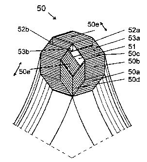
A 10-sided leg, generally designated 50, will now be
described with reference to fig. S. The profiled rings
contain all four rings with equal leg parts. A first
ring 50a, a second ring 50b and a third ring 50c with
5 rhombic cross-sections in their leg parts are attached
to the 10-sided cross-section. Thus they have the
angles 36, 72, and 108 degrees and their yoke parts
bent 24 degrees. A fourth ring 50d having a rhomboid
cross-section with the angle 36 degrees lies mainly
10 upon the first ring 50a. Its leg parts are turned out-
wards 24 degrees, causing a 48 degrees bending of its
yokes. The fourth ring also causes the yoke parts of
the third ring 50c to make a larger bow to give space.
A fifth ring 50e has a rhombic cross-section in its leg
parts with the angle 144 degrees when it lies outside
of the third ring 50c, but the ring has a rhombic
cross-section with the angle 72 degrees when it lies
outside of the fourth ring 50d. The yokes are bent only
12 degrees. The arrows i the figure indicate that the
cross-sections 50e belong to different profiled rings.
There will also be a channel 51 suitable for cooling
the legs. In an alternative embodiment, the channel is
filled with a ring. This is an advantage when the rings
co-operate by letting the magnetic field go between
them. The space can e.g. be disposed of in such a way
that the upper part of the rings 50c obtains new rhom-
bic cross-sections with the angle 72 degrees, causing
the channels 52a and 52b to be formed. Further parts of
ring 50c to the right can be pushed to ring 50e, which
forms the spaces 53a and 53b.
It is possible to provide three-phase transformer cores
with even more edges. Fig. 6 shows a 12-sided core,
CA 02342331 2001-02-28
WO 00/14753 PCT/SE99/01518
11
generally designated 60. The profiled rings are com-
posed of four rings 60a-d with rhombic cross-sections
with the angles 30, 60, 90, and 120 degrees, which are
attached to the 12-sided cross-section and are turned
15 degrees. Inside of these rings there are two rings
60e, 60f with rhombic cross-sections with the angles 30
and 60 degrees, respectively, and turned outward 15
degrees. Attached to the fifth and sixth rings 60e, 60f
there is space for a ring 60g with a rhombic cross-
section with the angle 30 degrees turned outward 45
degrees. Its other leg part is a rectangle outside of
the sixth ring 60f and turned outward 15 degrees. Upon
the ring 60d there is space for a ring 60h with a rhom-
bic cross-section with the angle :L50 degrees and the
other leg part is a rectangle attached to ring 60d and
outside ring 60f. The whole cross-section is then
filled. Yoke parts are separated by giving some wider
bows to give space for other yoke parts.
The good properties of these transformer cores can be
made even better for some transformer application, see
fig. 7. The leakage inductance can easily be increased
by an additional core 29 of strips between the primary
and secondary windings of the transformer. The strips
are brought together at the top and bottom. The strips
can be spread around the entire primary winding or be
concentrated to one place, making the secondary winding
eccentric.
The non-linear magnetic properties of iron result in
harmonics in the magnetic fields, voltages and cur-
rents.
CA 02342331 2001-02-28
WO 00/14753 PCT/SE99/01518
12
An additional leg placed in the centre of the core will
not get any magnetic field under perfectly symmetrical
and distortion-free three-phase conditions. Common com-
ponents in the phase voltages, like the third harmon-
ics, will be influenced by a centre leg.
Also a combination of strips between the windings and a
centre leg is possible.
In one embodiment, the centre leg is made of three rec-
tangular poles 80 from strips given. a height three
times the width, laid on each other= to a quadratic
cross-section, see fig. 8. This is preferably triangu-
lar and a custom-made solution cont.ains poles with a
rhombic cross-section, of which three are put together
to form a packet with the strip edges toward each other
in a wave form, see fig. 9. Three packets are put to-
gether with small distances to form a leg with a cross-
section approximating a triangle. The ends of the poles
are bent outward to reach the yokes. To make the bends
possible spacers between the poles are necessary. The
spacers do not influence the magnetic properties be-
cause one pole from each packet 91a-c; 92a-c; 93a-c is
bent to each yoke. Also the strips are, at least on one
side, parallel to the spacers.
A rod, wound of strips in spiral form or as coils, is
useful, especially if there are to be air gaps between
the centre leg and the yokes. The spiral can be made
wider at the ends to reduce the air gaps to the yokes.
The flexibility of building cores like this is good and
is shown in fig. 10. The figure shows the core de-
scribed in connection with fig. 4. A major part of the
CA 02342331 2001-02-28
WO 00/14753 PCT/SE99/01518
13
magnetic flux can pass from one profiled ring to
another in the legs where they are touching each other.
This enables the rotation of larger fluxes in the yoke
triangle.
With the present invention, it is also possible to pro-
vide a three-phase transformer core with lined up legs.
This has the advantage that the transformer is narrower
than with the delta shaped core. This type of trans-
former is ideal for placement on e.g. train wagons.
Fig. ila shows the transverse cross-section of a trans-
former with octagonal legs. All legs comprise four
rhombs with an angle of 45 degrees and two squares.
Rings running between adjacent legs are shown in the
figure while those running between the outer legs are
almost entirely hidden.
In order to make transformer cores of this kind, the
leg parts must be bendable and that the yoke parts can
be bent and pass each other. There are several solu-
tions, of which one is shown in the figure. The leg
parts of the rings are bent outward and the yoke part
inward or vice versa. The shape of the yoke parts is
limited by the limited possibilities of plastic defor-
mations but otherwise the yoke parts can have any
shape. The principle shown in fig. 11 is to have sharp
bends and straight yoke parts.
The rings can also be placed on each other giving
rounded bends in order to save material.
The yokes between the left leg 115 and the centre leg
116 are built up of a ring 112a with a rhombic cross-
section in the leg part, a ring 112b with a square
CA 02342331 2001-02-28
WO 00/14753 14 PCT/SE99/01518
cross-section and both bent 22.5 degrees and a rhombic
ring 112c turned 67.5 degrees in the leg parts. The
rings 112a and 112b fit into the octahedrons close to
the yoke side while the ring 112c fits into the oppos-
ing side.
The yoke between the centre leg 116 and the right leg
117 can only be placed in the centre leg in the remain-
ing positions: 114a-c. The cross-sections of the left
and right legs 115, 117 are mirror images to the centre
leg 116 so that the rings running in the centre leg are
symmetric. The inner rings 114a, 114b have their clos-
est positions in the right leg 117.. However, the ring
114c with a square cross-section in the leg parts runs
to the closest square-shaped position in the right leg.
The reason behind that is that the ring 113a with a
square cross-section between the outer legs is in an
outer position on the yoke parts already present in
order to reach the left leg.
The turning of the yokes can be impossible to achieve.
In an alternative embodiment, a heavily sloping fold is
used instead. This is shown for the ring 114c having
the shortest yoke. The fold starts at one end of the
yoke and ends at the other end, marked by 118a for the
lower yoke and 118b for the upper yoke in fig. 11.
Also, the yokes can be subdivided into several narrow
rings.
Also single-phase transformers will be more efficient
if they are given polygonal cross-sections. Fig. 12
shows a transformer with an octagonal cross-section
composed of rings with the same cross-sections as in
the three-phase transformers but with the return loops
CA 02342331 2001-02-28
WO 00/14753 PCT/SE99/01518
is
going the closest way outside of the windings. The
rings can be transposed and yet given an octagonal
cross-section. A small reduction of the amount of plate
can e.g. be obtained by looping up to the left of the
ring looping rightmost in the figure. There must its
cross-section be changed to a rhombic form close to
rectangular form.
A core with two legs can be made from the three-phase
designs by bending the rings from one leg together to
form only one more leg. A core is shown in fig. 13 with
an octagonal cross-section in its legs. The turning of
three leg-parts is 45 degrees and the bending is 90
degrees. A ring with a rectangular cross-section and
the two rings outside of that ring are not deformed.
Cores with hexagonal legs need only three rings made of
strips with the same width.
If that octagon edge where three rhomb edges meet, is
put innermost in the core, the turnings will only be
22.5 degrees except for the rhomb in the middle, which
must be turned 67.5 degrees. Replacing this rhomb with
a ring, with steps approximating the rhomb, is more
realistic and is shown in fig. 14. A further improve-
ment is made by letting the strips reach the circle,
thus increasing the total cross-section.
The segments outside of a polygonal leg can be filled
by a thin rhombic ring of a strip with about half the
width and the full height of the segment and wound to
its total width. Folds in the strips along the middle
of the rhomb as in fig. 15 make two sides to one flat
side giving a triangle, the sides of which are in con-
tact with the core. With about 2/3 width and 8/9
CA 02342331 2001-02-28
WO 00/14753 16 PCT/SE99/01518
height, a fold at the edge of the innermost strip makes
a trapezoid cross-section as in fig. 16. The cross-
section can also be rounded.
By means of strips of constant width the leg parts can
be given a cross-section shape closer to the shape of a
circle, see fig. 17, 17a and 17b. The right leg 172 in
fig. 17 will be described as an example with reference
to fig. 17a, wherein a transverse cross-section of that
leg is shown. Innermost, there are rings 173 of e.g.
800 of full width and to a height of 9% of its width.
There are three rings reaching a circumscribed circle,
see fig. 17a.
Four of the six segments have been filled with magnetic
material and strips outside of the assembled core can
fill the other segments.
A ring 174 can be placed on the outer sides of the
hexagons.
Another embodiment is shown in fig. 17b, wherein the
ring 174 has been replaced by broader strips in the
other rings.
Some of the advantages of the inventive transformer
core have already been mentioned. Among the other
advantages can be mentioned: lower no load losses, less
weight, less volume, lower electrical leakage, a reduc-
tion of harmonics due to the symmetry of the phases of
the three-phase transformer, easy maintenance etc.
Preferred embodiments of a transformer core according
the invention have been described. The person skilled
CA 02342331 2001-02-28
WO 00/14753 17 PCT/SE99/01518
in the art realises that these can be varied within the
scope of the claims.