Language selection

Search

Patent 2342399 Summary

Third-party information liability

Some of the information on this Web page has been provided by external sources. The Government of Canada is not responsible for the accuracy, reliability or currency of the information supplied by external sources. Users wishing to rely upon this information should consult directly with the source of the information. Content provided by external sources is not subject to official languages, privacy and accessibility requirements.

Claims and Abstract availability

Any discrepancies in the text and image of the Claims and Abstract are due to differing posting times. Text of the Claims and Abstract are posted:

  • At the time the application is open to public inspection;
  • At the time of issue of the patent (grant).
(12) Patent: (11) CA 2342399
(54) English Title: SIDE AIRBAG RETENTION SYSTEM AND FASTENER
(54) French Title: SYSTEME DE RETENUE ET DISPOSITIF DE FIXATION DE COUSSIN GONFLABLE
Status: Expired and beyond the Period of Reversal
Bibliographic Data
(51) International Patent Classification (IPC):
  • B60R 21/16 (2006.01)
  • B60R 21/20 (2011.01)
  • B60R 21/213 (2011.01)
  • F16B 21/09 (2006.01)
  • F16B 39/00 (2006.01)
(72) Inventors :
  • LEVEY, KENNETH R. (United States of America)
  • PARKER, ERIC (United States of America)
  • CISTERNINO, FRANCO (United States of America)
  • ANDERSON, JEFFREY D. (United States of America)
(73) Owners :
  • ILLINOIS TOOL WORKS INC.
(71) Applicants :
  • ILLINOIS TOOL WORKS INC. (United States of America)
(74) Agent: FINLAYSON & SINGLEHURST
(74) Associate agent:
(45) Issued: 2005-05-31
(22) Filed Date: 2001-03-27
(41) Open to Public Inspection: 2001-09-30
Examination requested: 2001-03-27
Availability of licence: N/A
Dedicated to the Public: N/A
(25) Language of filing: English

Patent Cooperation Treaty (PCT): No

(30) Application Priority Data:
Application No. Country/Territory Date
09/595,306 (United States of America) 2000-06-16
60/193,524 (United States of America) 2000-03-31

Abstracts

English Abstract


A side airbag retention system for installation in a keyhole opening including
a bolt with a generally conical head portion and a shaft disposed through an
aperture of the air
bag retainer, and a bolt retainer disposed about the bolt shaft between the
bolt head and the air
bag retainer. The bolt retainer preferably includes a spring washer having a
pronged
engagement member extending generally radially therefrom between anti-rotation
tabs
extending from a side thereof opposite the bolt head, and a compression
limiting member
disposed about and protruding from the washer opening toward the bolt head.


Claims

Note: Claims are shown in the official language in which they were submitted.

The embodiments of the invention in which an exclusive property or privilege
is claimed are
defined as follows:
1. A side airbag retention system for use in conjunction with a panel member
having a first side, a second side and a hole therethrough, the system
comprising:
an airbag retainer having an aperture;
a bolt having a shaft and a conical head portion, the bolt shaft disposed
through
the aperture of the air bag retainer; and
a bolt retainer disposed about the bolt shaft between the bolt head and the
airbag retainer, such that the airbag retainer is secured to the panel member
by passing the
bolt head through the opening in the panel member so that the bolt head is
positioned on the
first side of the panel member and the bolt retainer is positioned on the
second side of the
panel member.
2. The system of claim 1, the, bolt retainer comprising a spring washer
portion
having an opening and an engagement member extending from an end thereof, the
engagement member having a prong protruding from a side thereof facing the
bolt head
portion, the prong extending away from the opening of the spring washer
portion.
3. The system of claim 2, the spring washer portion having an annular member
disposed about the opening thereof, the annular member protruding from a side
of the spring
washer portion facing the head portion of the bolt, the bolt coupled to the
airbag retainer by
a nut.
4. The system of claim 2, the spring washer portion having resilient portions
biased toward the bolt head portion, the prong disposed on a portion of the
engagement
member extending generally radially beyond the bolt head portion.
5. The system of claim 2, the bolt retainer having an anti-rotation member
extending therefrom toward the airbag retainer.
6. The system of claim 5, the aperture of the airbag retainer near an end
portion
6

thereof, the anti-rotation member comprising two tabs extending from a side of
the spring
washer portion facing the airbag retainer, the two tabs adjacent the end
portion of the airbag
retainer, the engagement member extending from the end of the spring washer
portion
between the two tabs.
7. A retention system comprising:
an article;
a bolt having a head and a shaft fastened to the article;
a spring washer disposed about the bolt shaft between the bolt head and the
article;
an annular member disposed about the opening of the spring washer and
protruding from a side thereof facing the bolt head, the annular member being
adapted to seat
against the head of the bolt to limit compression of the spring washer between
the head of
the bolt and the article;
an engagement member extending from the spring washer generally radially
therefrom; and
a prong protruding from a side of the engagement member facing the bolt., the
prong extending generally away from the bolt shaft.
8. The system of claim 7, the spring washer having a resilient portion biased
toward the head portion of the bolt.
9. The system of claim 7, the spring washer having an anti-rotation member
extending therefrom toward the article.
10. The system of claim 9, the article having an aperture near an end portion
thereof, the anti-rotation member comprising two tabs extending from a side of
the spring
washer facing the article, the two tabs adjacent the end portion of the
article.
11. The system of claim 7, the bolt having a wrenching surface and a generally
conical head portion protruding axially therefrom.
7

12. The system of claim 7 further comprising a panel with an opening between
first
and second opposite sides thereof, the panel captured between the prong on one
side of the
panel and a portion of the engagement member on an opposite side thereof.
13. The system of claim 7,
the bolt head having a generally conical head portion;
the spring washer having a resilient portion biased toward the head portion of
the bolt;
the prong disposed on a portion of the engagement member extending beyond
the head portion of the bolt, the engagement member biased toward the bolt
head;
two tabs extending from a side of the spring washer facing the article, the
two
tabs adjacent and engageable with the article.
14. The system of claim 7, the spring washer and engagement member constitute
a unitary metal member.
15. A keyhole retention assembly comprising:
a bolt having a shaft and a generally conical head:
a spring washer disposed about the bolt shaft;
a protuberance disposed about the bolt shaft, the spring washer being captured
between the bolt head and the protuberance;
an engagement member extending from the spring washer generally radially
therefrom; and
a prong protruding from a side of the engagement member facing the bolt head,
the prong extending away from the bolt shaft.
16. The assembly of claim 15, an annular member disposed about an opening of
the spring washer, the annular member protruding from a side of the spring
washer facing the
bolt head.
17. The assembly of claim 15, the spring washer having a resilient portion
biased
toward the bolt head.
8

18. The assembly of claim 15, two tabs extending from a side of the spring
washer
opposite the bolt head, the engagement member extending between the two tabs.
19. The assembly of claim 18, an annular member disposed about an opening of
the spring washer, the annular member protruding from a side of the spring
washer facing the
bolt head.
20. An airbag retention assembly comprising:
a panel member having a front side, a back side and a keyhole that includes a
first opening and a second opening which is generally smaller than the first
opening;
an airbag retainer for holding an airbag until deployment of the airbag, the
airbag retainer having a first portion for substantially surrounding the
airbag, a second portion
defined by a pair of generally parallel arm members extending outward from the
first portion
and an aperture extending through the arm members;
a bolt member having a head and a shaft which is disposed through the aperture
extending through the arm members of the retainer; and
a bolt retainer disposed about the bolt shaft between the bolt head and the
airbag retainer, the bolt retainer having an opening for receiving the bolt
shaft and a
protruding engagement member, such that the airbag retainer is secured to the
panel member
by passing the bolt head through the first opening of the panel member so that
the bolt head
is positioned on the front side of the panel member and the bolt retainer is
positioned on the
back side of the panel member and laterally moving the bolt member from the
first opening
of the panel member to the second opening of the panel member, the second
opening of the
panel member being appropriately sized so that the bolt head, once positioned
therein, cannot
be moved through the panel member and the bolt member being moved into the
second
opening of the panel member until the engagement member of the bolt retainer
engages the
front side of the panel member, thereby securely attaching the airbag retainer
of the panel
member.
21. The airbag retention assembly of claim 20, wherein the bolt head has a
generally conical shape so that the bolt head is more easily received by the
panel member.
9

22. The airbag retention assembly of claim 20, wherein the retention assembly
further includes a nut threadably received by the bolt member so as to provide
a clamp load
to the airbag retainer to selectively hold the airbag within the airbag
retainer.
23. The airbag retention assembly of claim 20, wherein the bolt retainer
includes
a spring washer which defines the bolt retainer opening, the spring washer
including a first
resilient portion and a second resilient portion both of which are curved
toward the bolt head
and positioned on opposite sides of the bolt retainer opening, the spring
washer being adapted
to provide an axial retention force toward the bolt head.
24. The airbag retention assembly of claim 20, wherein the engagement member
of the bolt retainer includes a prong formed on an end portion and between a
pair of opposite
lateral side portions thereof, such that when the airbag retainer is securely
attached to the
panel member, the prong of the engagement member of the bolt retainer engages
one of the
front side and the back side of the panel member and the lateral side portions
of the
engagement member of the panel member engages the other of the front side and
the back
side of the panel member.
25. The airbag retention assembly of claim 20, wherein the engagement member
of the bolt retainer is a resilient member and is biased toward the bolt bead,
such that during
attachment of the airbag retainer to the panel member, the engagement member
is adapted to
provide an audible sound indicating that the airbag retainer has been securely
attached to the
panel member.
26. The airbag retention assembly of claim 20, wherein the bolt retainer
includes
an annular member which surrounds the bolt retainer opening, such that the
annular member
seats against the bolt head to limit the compression of the bolt retainer
between the bolt head
and the panel member.
27. The airbag retention assembly of claim 20, wherein the bolt retainer
includes
an anti-rotation device that prevents the rotation of the bolt retainer
relative to the airbag
retainer.

28. The airbag retention assembly of claim 27, wherein the anti-rotation
device
includes a pair of tabs extending from a side of the bolt retainer opposite
the bolt head, the
tabs being adapted to contact the airbag retainer for preventing the rotation
of the bolt retainer
relative to the airbag retainer.
29. The airbag retention assembly of claim 20, wherein the bolt member
includes
a generally annular protuberance disposed about the bolt shaft to capture the
bolt retainer
between the bolt head and the protuberance.
11

Description

Note: Descriptions are shown in the official language in which they were submitted.


CA 02342399 2004-06-11
SIDE AIRBAG RETENTION SYSTEM AND FASTENER
BACKGROUND OF THE INVENTION
The invention relates generally to fastener retainers and more particularly to
side airbag retention systems and fasteners therefor.
Bolt retainers for retaining bolts, for example in keyhole openings, are known
generally.
The present invention seeks to provide novel retention systems and fasteners
therefor that improve upon and overcome problems in the art.
Further, the invention seeks to provide novel side airbag retention systems
and
fasteners therefor that are more securely fastenable to keyhole openings and
which may be
installed blindly.
Still further the invention seeks to provide novel side airbag retention
systems
and fasteners therefor that provide an audible indication upon installation
and that do not
rattle when installed.
The side airbag retention systems and fasteners of the invention are therefore
re-useable, for example after deployment of the airbag.
Yet further, the invention seeks to provide novel side airbag retention
systems
and fasteners therefor that maintain rotation alignment during assembly and
installation and
that provide a continuous mounting force.
The invention seeks to provide novel side airbag retention systems comprising
an airbag retainer, a bolt having a generally conical head portion and a shaft
disposed
through an aperture of the airbag retainer and a bolt retainer disposed about
the bolt shaft
between the bolt head and the airbag retainer.
More particularly, the invention in one aspect provides a keyhole retention
assembly comprising a bolt having a shaft and a generally conical head, a
spring washer
disposed about the bolt shaft and a protuberance disposed about the bolt
shaft, the spring
washer being captured between the bolt head and the protuberance. An
engagement
member extends from the spring washer generally radially therefrom and a prong
protrudes
from a side of the engagement member facing the bolt bead, the prong extending
away

CA 02342399 2004-06-11
from the bolt shaft.
Another aspect of the invention provides a side airbag retention systen-v for
use in conjunction with a panel member having a first side, a second side and
a hole
therethrough. The system comprises an airbag retainer having an aperture, a
bolt having
a shaft and a conical head portion, the bolt shaft disposed through the
aperture of the airbag
retainer and a bolt retainer disposed about the bolt shaft between the bolt
head and the
airbag retainer, such that the airbag retainer is secured to the panel member
by passing the
bolt head through the opening in the panel member so that the bolt head is
positioned on
the first side of the panel member and the bolt retainer is positioned on the
second side of
the panel member.
Further the invention comprehends a retention system comprising an article,
a bolt having a head and a shaft fastened to the article with a spring washer
disposed about
the bolt shaft between the bolt head and the article. An annular member is
disposed about
the opening of the spring washer and protrudes from a side thereof facing the
bolt head, the
annular member being adapted to seat against the head of the bolt to limit
compression of
the spring washer between the head of the bolt and the article. An engagement
member
extends from the spring washer generally radially therefrom and a prong
protrudes from a
side of the engagement member facing the bolt, the prong extending generally
away from
the bolt shaft.
These and other aspects, features and advantages of the present invention will
become more fully apparent upon careful consideration of the following
Detailed
Description of the Invention and the accompanying Drawings, which may be
disproportionate for ease of understanding, wherein like structure and steps
are referenced
generally by corresponding numerals and indicators.
2

CA 02342399 2004-06-11
BRIEF DESCRIPTION OF THE DRAWINGS
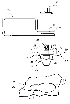
FIG. 1 is an exemplary side airbag retention system for installation in a
keyhole
opening.
FIG. 2 is a partial view of an assembled and installed side airbag retention
system.
DETAILED DESCRIPTION OF THE INVENTION
FIG. 1 illustrates a bolt retention assembly for fastening an article to a
panel '20
having a keyhole 22 with relatively small and large opening portions 23 and
25, respectively.
In the exemplary application, the article is a side airbag retainer 10 having
an
aperture 12 through one or more portions thereof, and the panel 20 is an
interior roof portion
near the A and B pillars of an automobile.
In FIG. 1, the bolt retention assembly comprises a bolt having a shaft 30
preferably having a threaded portion 32 and a head 34. The bolt is disposable
through the
aperture 12 of the airbag retainer 10 and is generally coupled thereto, for
example by a nut 4()
or by threaded engagement with a threaded portion of the aperture 12. The
exemplary bolt
head includes a wrenching surface 35, but other embodiments may include some
other torque
transmitting configuration.
The exemplary bolt head also includes a generally conical head portion 36
having a relatively narrow end portion protruding axially therefrom. The
conical head portion
2 0 facilitates insertion thereof into the keyhole or other opening, and is
particularly desirable in
applications where installation is performed blindly. In the exemplary side
airbag application,
for example, the airbag retainer is installed on the interior roof of the
passenger compartment
from outside the vehicle, where the keyhole is not readily visible to the
installer.
The bolt retention assembly also comprises a bolt retainer for retaining the
3

CA 02342399 2004-06-11
assembly in the keyhole or opening. The exemplary bolt retainer generally
compri ses a spring
washer 50 disposed about the bolt shaft, and an ~ugagement member 60 extending
from the
spring washer generally radially, and preferably beyond or outwardly of the
bolt head.
The spring washer 50 generally comprises one or more resilient portions biased
toward the bolt head for applying an axial retention force thereto. In FIG. 1,
the exemplary
spring washer has resilient portions S l and 53 curved toward the bolt head on
opposite sides
of the washer opening. In other embodiments, the spring washer may have a
radial or other
wave form.
In FIG. l, the engagement member preferably includes a prong 62 protniding
from a side thereof facing the bolt head. The prong 62 extends generally away
from the bolt
shaft. In the exemplary embodiment of FIG. 2, the prong 62 is formed, for
example in a
stamping operation, at or on an end portion of the engagement member 60
between opposite
lateral side portions 64 and 65 thereof.
In FIG. 1, the prong 62 is preferably disposed on a portion of the engagement
member extending outwardly beyond the head portion of the bolt. The prong 62
is also
preferably spaced from the opening of the spring washer so that the prong is
engageable with
an edge of the larger keyhole opening portion 25 after the bolt is laterally
positioned therefrom
to the smaller keyhole opening portion 23, as illustrated best in FIG. 2.
The engagement member 60 is preferably resilient and is biased toward the bolt
head 34. During installation of the bolt retention assembly with the airbag
retainer or other
article, the engagement member provides an audible sound indicating that the
prong is engaged
with the opening and that installation is complete.
In FIG. 2, the prong 62 preferably protrudes sufficiently far from the side of
the
engagement member 60 facing the bolt head to permit capturing the panel 20
between the
prong 62 and the lateral side portions 64 and 65 of the engagement member 60.
In FIG. l, the spring washer 50 preferably includes an annular member or
portion 54, which may be a continuous member or comprised of discrete
portions, disposed
about the washer opening and protruding from the side thereof facing the bolt
head. Upon
4

CA 02342399 2004-06-11
assembly, the annular member 54 seats against the bolt head and limits
compression of the
spring washer between the bolt head unci panel during tightening of the nut or
other bolt
engagement means.
The bolt retainer preferably includes an anti-rotation member for preventing
rotation thereof during assembly with the article or exemplary airbag retainer
10. In FIG. l , the
aperture 12 of the airbag retainer 10 is near an end portion 14 thereof, and
the anti-rotation
member comprises two tabs (only tab 72 is visible in FIG. 1) extending from
the side of the
retainer opposite the bolt head.
In FIG. 2, the tabs 71 and 72 are disposed on opposite sides of the engagement
member 60 extending from the end of the spring washer. Upon installation of
the bolt
retention assembly with the article or airbag retainer 10, the two tabs 71 and
72 are adjacent
and engageable with the end portion 14 thereof to prevent rotation of the
washer.
In FIG. l, a generally annular protuberance 38 is disposed about the bolt
shaft
to capture the spring washer 50 between the bolt head 34 and the protuberance
38.
The exemplary bolt retainer is preferably a unitary member, for example spring
steel formed in a stamping or other forming operation, but may be formed as an
assembly in
other embodiments.
alternative embodiments of the invention may include other known bolt
retainers.
While the foregoing written description ofthe invention enables one of
ordinary
skill to make and use what is considered presently to be the best mode
thereof, those of
ordinary skill will understand and appreciate the existence of variations,
combinations, and
equivalents of the specific exemplary embodiments herein. The invention is
therefore to be
limited not by the exemplary embodiments herein, but by all embodiments within
the scope
and spirit of the appended claims.
5

Representative Drawing
A single figure which represents the drawing illustrating the invention.
Administrative Status

2024-08-01:As part of the Next Generation Patents (NGP) transition, the Canadian Patents Database (CPD) now contains a more detailed Event History, which replicates the Event Log of our new back-office solution.

Please note that "Inactive:" events refers to events no longer in use in our new back-office solution.

For a clearer understanding of the status of the application/patent presented on this page, the site Disclaimer , as well as the definitions for Patent , Event History , Maintenance Fee  and Payment History  should be consulted.

Event History

Description Date
Inactive: IPC from PCS 2022-09-10
Time Limit for Reversal Expired 2012-03-27
Letter Sent 2011-03-28
Inactive: IPC expired 2011-01-01
Inactive: IPC from MCD 2006-03-12
Grant by Issuance 2005-05-31
Inactive: Cover page published 2005-05-30
Pre-grant 2005-03-07
Inactive: Final fee received 2005-03-07
Notice of Allowance is Issued 2004-09-17
Letter Sent 2004-09-17
Inactive: Approved for allowance (AFA) 2004-09-08
Amendment Received - Voluntary Amendment 2004-06-11
Inactive: S.30(2) Rules - Examiner requisition 2003-12-29
Inactive: S.29 Rules - Examiner requisition 2003-12-29
Application Published (Open to Public Inspection) 2001-09-30
Inactive: Cover page published 2001-09-30
Inactive: IPC assigned 2001-07-03
Inactive: First IPC assigned 2001-07-03
Application Received - Regular National 2001-05-01
Letter Sent 2001-05-01
Inactive: Filing certificate - RFE (English) 2001-05-01
Request for Examination Requirements Determined Compliant 2001-03-27
All Requirements for Examination Determined Compliant 2001-03-27

Abandonment History

There is no abandonment history.

Maintenance Fee

The last payment was received on 2005-03-07

Note : If the full payment has not been received on or before the date indicated, a further fee may be required which may be one of the following

  • the reinstatement fee;
  • the late payment fee; or
  • additional fee to reverse deemed expiry.

Patent fees are adjusted on the 1st of January every year. The amounts above are the current amounts if received by December 31 of the current year.
Please refer to the CIPO Patent Fees web page to see all current fee amounts.

Owners on Record

Note: Records showing the ownership history in alphabetical order.

Current Owners on Record
ILLINOIS TOOL WORKS INC.
Past Owners on Record
ERIC PARKER
FRANCO CISTERNINO
JEFFREY D. ANDERSON
KENNETH R. LEVEY
Past Owners that do not appear in the "Owners on Record" listing will appear in other documentation within the application.
Documents

To view selected files, please enter reCAPTCHA code :


To view images, click a link in the Document Description column. To download the documents, select one or more checkboxes in the first column and then click the "Download Selected in PDF format (Zip Archive)" or the "Download Selected as Single PDF" button.

List of published and non-published patent-specific documents on the CPD .

If you have any difficulty accessing content, you can call the Client Service Centre at 1-866-997-1936 or send them an e-mail at CIPO Client Service Centre.


Document
Description 
Date
(yyyy-mm-dd) 
Number of pages   Size of Image (KB) 
Representative drawing 2001-07-03 1 6
Description 2001-03-26 5 280
Abstract 2001-03-26 1 21
Drawings 2001-03-26 2 42
Claims 2001-03-26 5 151
Abstract 2004-06-10 1 16
Description 2004-06-10 5 231
Claims 2004-06-10 6 233
Representative drawing 2005-04-27 1 7
Courtesy - Certificate of registration (related document(s)) 2001-04-30 1 113
Filing Certificate (English) 2001-04-30 1 164
Reminder of maintenance fee due 2002-11-27 1 106
Commissioner's Notice - Application Found Allowable 2004-09-16 1 160
Maintenance Fee Notice 2011-05-08 1 171
Correspondence 2005-03-06 1 28