Language selection

Search

Patent 2342572 Summary

Third-party information liability

Some of the information on this Web page has been provided by external sources. The Government of Canada is not responsible for the accuracy, reliability or currency of the information supplied by external sources. Users wishing to rely upon this information should consult directly with the source of the information. Content provided by external sources is not subject to official languages, privacy and accessibility requirements.

Claims and Abstract availability

Any discrepancies in the text and image of the Claims and Abstract are due to differing posting times. Text of the Claims and Abstract are posted:

  • At the time the application is open to public inspection;
  • At the time of issue of the patent (grant).
(12) Patent Application: (11) CA 2342572
(54) English Title: SAWHORSE BRACKETS
(54) French Title: SUPPORTS DE CHEVALET DE SCIAGE
Status: Deemed Abandoned and Beyond the Period of Reinstatement - Pending Response to Notice of Disregarded Communication
Bibliographic Data
(51) International Patent Classification (IPC):
  • F16M 11/00 (2006.01)
  • B25H 1/06 (2006.01)
  • B27B 21/00 (2006.01)
(72) Inventors :
  • MCGILLIS, LAWRENCE ROBERT (Canada)
  • PEDERSEN, BJARNE THORKILD (Canada)
(73) Owners :
  • LAWRENCE ROBERT MCGILLIS
  • BJARNE THORKILD PEDERSEN
(71) Applicants :
  • LAWRENCE ROBERT MCGILLIS (Canada)
  • BJARNE THORKILD PEDERSEN (Canada)
(74) Agent: THOMPSON LAMBERT LLP
(74) Associate agent:
(45) Issued:
(22) Filed Date: 2001-03-30
(41) Open to Public Inspection: 2002-09-30
Availability of licence: N/A
Dedicated to the Public: N/A
(25) Language of filing: English

Patent Cooperation Treaty (PCT): No

(30) Application Priority Data: None

Abstracts

English Abstract


Sawhorse brackets include a pair of rigid metal bodies.
Each body has a receptacle with an axis and two legs that
depend from the body. The legs are positioned along a plane
which is transverse to the axis and diverge from the axis. The
rigid legs increase the strength of the resulting sawhorse.


Claims

Note: Claims are shown in the official language in which they were submitted.

5
THE EMBODIMENTS OF THE INVENTION IN WHICH AN EXCLUSIVE PROPERTY
OR PRIVILEGE IS CLAIMED ARE DEFINED AS FOLLOWS:
1. Sawhorse brackets, comprising:
a pair of rigid metal bodies, each body having:
a receptacle with an axis; and
two legs which depend from the body, the legs being
positioned along a plane which is transverse to the axis, the
legs diverging from the axis.
2. The sawhorse bracket as defined in Claim 1, wherein the
bodies are capable of stacking for transportation and storage.

Description

Note: Descriptions are shown in the official language in which they were submitted.


CA 02342572 2001-03-30
1
TITLE OF THE INVENTION:
Sawhorse Brackets
FIELD OF THE INVENTION
The present invention relates to a pair of brackets that
are used to fabricate a sawhorse
BACKGROUND OF THE INVENTION
In order to avoid having to transport complete sawhorses
between worksites, sawhorse brackets have:been developed. These
sawhorse brackets enable workmen to quickly fabricate a
sawhorse at a worksite using readily available construction
materials. Examples of such sawhorse brackets are illustrated
in United States Patents 860,161 (Thomas 1907), 2,753,222
(Foresta et al 1956) , 4, 770, 274 (Middleton. 1988) , and 5, 484, 037
(Neumarkel 1996).
SUMMARY OF THE INVENTION
The present invention relates to an alternative
configuration of sawhorse brackets.
According to the present invention t=here is provided
sawhorse brackets which include a pair of: rigid metal bodies.
Each body has a receptacle with an axis and two legs that
depend from the body. The legs are positioned along a plane
which is transverse to and diverge from i~he axis.
The sawhorse brackets, as described above, enables a
sawhorse to be readily assembled by inserting a 2 X 6 member
in a bridging position between the receptacles of two brackets.
The resulting sawhorse has rigid legs fabricated from either
plastic or metal, and is, as a consequence, much stronger than
sawhorses that could be assembled using previously known
sawhorse brackets. The convenience of ease of transport is
maintained. The strength of the assembled sawhorse can be
increased by doubling up or otherwise reinforcing the 2 X 6
member used for bridging between two bra~~kets.

CA 02342572 2001-03-30
2
BRIEF DESCRIPTION OF THE DRAHTINGS
These and other features of the invention will become more
apparent from the following description i.n which reference is
made to the appended drawings, the drawings are for the purpose
of illustration only and are not intended to in any way limit
the scope of the invention to the particular embodiment or
embodiments shown, wherein:
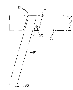
FIGURE 1 is a side elevation view of a saw horse bracket
constructed in accordance with the teachings of the present
invention.
FIGURE 2 is an end elevation view of 'the saw horse bracket
illustrated in FIGURE 1.
FIGURE 3 is side elevation view of a sawhorse fabricated
using the sawhorse bracket illustrated in FIGURE 1.
FIGURE 4 is an end elevation view of the sawhorse bracket
illustrated in FIGURE l, stacked on a second sawhorse bracket.
FIGURE 5 is a side elevation view of the sawhorse bracket
illustrated in FIGURE 1 stacked on a sect>nd sawhorse bracket.
DETAILED DESCRIPTION OF THE PREFERRED EMBODIMENT
The preferred embodiment, a saw horse bracket generally
identified by reference numeral 10, will now be described with
reference to FIGURES 1 through 5.
Structure and Relationship of Parts:
Referring to FIGURE 3, there is provided sawhorse brackets
10 which include a pair of rigid metal bodies 12. Each body 12
has a receptacle 14 and two legs 18 which depend from body 12.
Each receptacle has an axis 16. Referring to FIGURE 2, legs
18 are positioned along a plane 20 which :is transverse to axis
16, with legs 18 diverging from axis 16. Referring to FIGURE
1, in the illustrated embodiment, foot pads 22 are provided on
legs 18 to prevent legs 18 from sinking into soft ground at a
construction site.

CA 02342572 2001-03-30
3
Operation:
The use and operation of a sawhorse bracket 10 will now
be described with reference to FIGURES 1 through 5. Referring
to FIGURE 3, sawhorse brackets 10, as described above, enable
a sawhorse 24 to be readily assembled by inserting a wooden
member 26 (2 X 6) in a bridging position between receptacles
14 of two brackets 10. Referring to FIGURE 1, in the
illustrated embodiment, an aperture 28 that is adapted to
receive a screw 30 is provided on body 12. for securing wooden
member 26 against accidental withdrawal from receptacle 14.
Referring to FIGURE 3, resulting sawhorse 24 has rigid legs 18
that are made from metal or plastic and, as a consequence, much
stronger than sawhorses that could be assembled using
previously known sawhorse brackets in combination with scrap
lumber legs. Referring to FIGURE 2, in the illustrated
embodiment, the strength of the assembled sawhorse 24 is
increased by securing a second wooden member (2 X 4) 32 to
wooden member 26 used for bridging between two brackets 10,
although alternative materials can also be used to reinforce
member 26.
Referring to FIGURES 4 and 5, sawhorse brackets 10 can be
stacked on top of one another for ease of storage or
transportation. In the illustrated embodiment, two sawhorse
brackets 10, are shown as being stacked, however it will be
appreciated that numerous sawhorse brackets 10 could be stacked
in this manner.
In this patent document, the word "comprising" is used in
its non-limiting sense to mean that items following the word
are included, but items not specifically mentioned are not
excluded. A reference to an element by the indefinite article
"a" does not exclude the possibility that more than one of the
element is present, unless the context clearly requires that
there be one and only one of the elements.
It will be apparent to one skilled in the art that

CA 02342572 2001-03-30
4
modifications may be made to the illustrated embodiment without
departing from the spirit and scope of the invention as
hereinafter defined in the Claims.

Representative Drawing
A single figure which represents the drawing illustrating the invention.
Administrative Status

2024-08-01:As part of the Next Generation Patents (NGP) transition, the Canadian Patents Database (CPD) now contains a more detailed Event History, which replicates the Event Log of our new back-office solution.

Please note that "Inactive:" events refers to events no longer in use in our new back-office solution.

For a clearer understanding of the status of the application/patent presented on this page, the site Disclaimer , as well as the definitions for Patent , Event History , Maintenance Fee  and Payment History  should be consulted.

Event History

Description Date
Inactive: IPC from MCD 2006-03-12
Application Not Reinstated by Deadline 2005-03-30
Time Limit for Reversal Expired 2005-03-30
Deemed Abandoned - Failure to Respond to Maintenance Fee Notice 2004-03-30
Application Published (Open to Public Inspection) 2002-09-30
Inactive: Cover page published 2002-09-29
Inactive: IPC assigned 2001-06-15
Inactive: First IPC assigned 2001-06-15
Filing Requirements Determined Compliant 2001-05-03
Inactive: Filing certificate - No RFE (English) 2001-05-03
Application Received - Regular National 2001-05-02

Abandonment History

Abandonment Date Reason Reinstatement Date
2004-03-30

Maintenance Fee

The last payment was received on 2003-03-27

Note : If the full payment has not been received on or before the date indicated, a further fee may be required which may be one of the following

  • the reinstatement fee;
  • the late payment fee; or
  • additional fee to reverse deemed expiry.

Please refer to the CIPO Patent Fees web page to see all current fee amounts.

Fee History

Fee Type Anniversary Year Due Date Paid Date
Application fee - small 2001-03-30
MF (application, 2nd anniv.) - small 02 2003-03-31 2003-03-27
Owners on Record

Note: Records showing the ownership history in alphabetical order.

Current Owners on Record
LAWRENCE ROBERT MCGILLIS
BJARNE THORKILD PEDERSEN
Past Owners on Record
None
Past Owners that do not appear in the "Owners on Record" listing will appear in other documentation within the application.
Documents

To view selected files, please enter reCAPTCHA code :


To view images, click a link in the Document Description column. To download the documents, select one or more checkboxes in the first column and then click the "Download Selected in PDF format (Zip Archive)" or the "Download Selected as Single PDF" button.

List of published and non-published patent-specific documents on the CPD .

If you have any difficulty accessing content, you can call the Client Service Centre at 1-866-997-1936 or send them an e-mail at CIPO Client Service Centre.


Document
Description 
Date
(yyyy-mm-dd) 
Number of pages   Size of Image (KB) 
Representative drawing 2002-09-05 1 3
Abstract 2001-03-30 1 11
Description 2001-03-30 4 148
Drawings 2001-03-30 5 49
Claims 2001-03-30 1 16
Cover Page 2002-09-13 1 25
Filing Certificate (English) 2001-05-03 1 164
Reminder of maintenance fee due 2002-12-03 1 106
Courtesy - Abandonment Letter (Maintenance Fee) 2004-05-25 1 175
Fees 2003-03-27 1 28