Language selection

Search

Patent 2342749 Summary

Third-party information liability

Some of the information on this Web page has been provided by external sources. The Government of Canada is not responsible for the accuracy, reliability or currency of the information supplied by external sources. Users wishing to rely upon this information should consult directly with the source of the information. Content provided by external sources is not subject to official languages, privacy and accessibility requirements.

Claims and Abstract availability

Any discrepancies in the text and image of the Claims and Abstract are due to differing posting times. Text of the Claims and Abstract are posted:

  • At the time the application is open to public inspection;
  • At the time of issue of the patent (grant).
(12) Patent: (11) CA 2342749
(54) English Title: ELBOW CANISTER FUSEHOLDER
(54) French Title: PORTE-FUSIBLE A CARTOUCHE COUDEE
Status: Term Expired - Post Grant Beyond Limit
Bibliographic Data
(51) International Patent Classification (IPC):
  • H01R 33/05 (2006.01)
  • H01H 9/10 (2006.01)
  • H01H 85/20 (2006.01)
  • H01H 85/22 (2006.01)
  • H01R 33/95 (2006.01)
(72) Inventors :
  • STEPNIAK, FRANK (United States of America)
  • REED, ANTHONY (United States of America)
(73) Owners :
  • THOMAS & BETTS INTERNATIONAL, INC.
(71) Applicants :
  • THOMAS & BETTS INTERNATIONAL, INC. (United States of America)
(74) Agent: MACRAE & CO.
(74) Associate agent:
(45) Issued: 2008-03-11
(22) Filed Date: 2001-04-02
(41) Open to Public Inspection: 2001-10-04
Examination requested: 2003-08-11
Availability of licence: N/A
Dedicated to the Public: N/A
(25) Language of filing: English

Patent Cooperation Treaty (PCT): No

(30) Application Priority Data:
Application No. Country/Territory Date
60/194,458 (United States of America) 2000-04-04

Abstracts

English Abstract

A new elbow canister fuseholder is provided that includes an electrically insulated and shielded housing for placing a fuse in-line between a cable and an electrical apparatus for underground distribution application. An insulating tube is contained within the housing for easy sliding removal of the fuse through an end plug such that the elbow is reusable when a fuse is replaced.


French Abstract

Un nouveau porte-fusible à cartouche coudée comprend un logement électriquement isolé et blindé permettant de placer un fusible en ligne entre un câble et un appareil électrique pour une application de distribution souterraine. Un tube d'isolement est renfermé à l'intérieur du logement et permet de retirer facilement le fusible en le faisant glisser à travers une fiche d'extrémité, de sorte que le coude soit réutilisable lorsqu'un fusible est remplacé.

Claims

Note: Claims are shown in the official language in which they were submitted.

CLAIMS:
1. An elbow fuseholder, comprising:
a housing including a generally elongate insulative sleeve defining at one end
thereof a cable entrance
for receipt of a cable therein and at the opposing end a fuse entrance
opening;
an elbow interface joined to said sleeve at an angle and defining a mating
interface for electrical
connection with an external bushing insert;
a fuse electrically connected at one end to a conductor of said cable received
in said sleeve and
electrically connected at another end to said elbow mating interface;
an insulating tube disposed interiorly of said insulative sleeve, said fuse
being slidably supported
interiorly therein, said tube being elongate and of length to extend
substantially from the cable conductor
connection to the elbow interface; and
a plug removably supported by said insulative sleeve at said fuse entrance
opening and affixed to said
fuse adjacent said elbow mating interface, said plug and said fuse being
jointly removable from said sleeve
through said fuse opening upon removal of said plug from said sleeve.
2. An elbow fuseholder according to claim 1, further including an apparatus
for releasably securing said
plug to said sleeve.
3. An elbow fuseholder according to claim 2, wherein said apparatus includes a
metal contact attached
to said sleeve and releasable securement members selected from the group
consisting of threads, twist locks
and external clamps.
4. An elbow fuseholder according to claim 1, wherein said plug includes a
contact said fuse includes a
ferrule, said plug contact and fuse ferrule being detachably connected.
5. An elbow fuseholder according to claim 4, wherein said plug contact and
said fuse ferrule are
detachably connected by connection members selected from the group consisting
of setscrews, elbow probe
thread clamps and threads.
6

6. An elbow fuseholder according to claim 4, wherein said insulative sleeve
includes a cable conductor
contact adjacent said cable entrance.
7. An elbow fuseholder according to claim 6, wherein said cable conductor
contact is connected to a fuse
ferrule by securement members selected from the group consisting of garter
springs, louvers, and pins and
sockets.
8. An elbow fuseholder according to claim 1, wherein said insulative sleeve
adjacent said cable entrance
includes a cable adapter capable of receiving cables of different outer
diameters.
9. An elbow fuseholder according to claim 1, wherein said insulating sleeve is
molded rubber.
10. An elbow fuseholder according to claim 1, wherein said sleeve and said
elbow interface are joined at
a substantially right angle.
11. An elbow fuseholder, comprising:
a housing including a generally elongate insulative sleeve defining at one end
thereof a cable entrance
for receipt of a cable therein and at the opposing end a fuse entrance
opening;
an elbow interface joined to said sleeve at an angle and defining a mating
interface for electrical
connection with an external bushing insert;
a fuse electrically connected at one end to a conductor of said cable received
in said sleeve and
electrically connected at another end to said elbow mating interface;
an insulating tube disposed interiorly of said insulative sleeve, said fuse
being slidably supported
interiorly therein; and
a plug removably supported by said insulative sleeve at said fuse entrance
opening and affixed to said
fuse adjacent said elbow mating interface, said plug including a contact
thereon in electrical connection with
said fuse at said elbow mating interface, said plug, said contact and said
fuse being jointly removable from said
sleeve through said fuse opening upon removal of said plug from said sleeve.
12. An elbow fuseholder according to claim 1, further including an apparatus
for releasably securing said
plug to said sleeve.
7

13. An elbow fuseholder according to claim 12, wherein said fuse includes a
ferrule, said plug contact and
said fuse ferrule being detachably connected.
14. An elbow fuseholder, comprising:
a housing including a generally elongate insulative sleeve defining at one end
thereof a cable entrance
for receipt of a cable therein and at the opposing end a fuse entrance
opening;
an elbow interface joined to said sleeve at an angle and defining a mating
interface for electrical
connection with an external bushing insert;
a fuse having at one end a first projecting ferrule electrically connected to
a conductor of said cable
received in said sleeve and at another end a second projecting ferrule
electrically connected to said elbow
mating interface, said first ferrule being releasably received within a cable
contact secured to said cable
conductor;
an insulating tube disposed interiorly of said insulative sleeve, said fuse
being slidably supported
interiorly therein; and
a plug removably supported by said insulative sleeve at said fuse entrance
opening and affixed to said
fuse adjacent said elbow mating interface, said plug and said fuse being
jointly removable from said sleeve
through said fuse opening upon removal of said plug from said sleeve.
15. An elbow fuseholder according to claim 14, wherein said insulating tube
has a length extending
substantially from said first ferrule to said second ferrule.
16. An elbow fuseholder according to claim 15, wherein said insulative sleeve
adjacent said cable entrance
includes a separate cable adapter capable of receiving cables of different
outer diameter.
17. An elbow fuseholder according to claim 16, wherein said cable adapter is
supported in engagement
with said insulating tube and receives said cable contact therein.
8

Description

Note: Descriptions are shown in the official language in which they were submitted.


CA 02342749 2001-04-02
577-512 PATENT
T&B 1601
ELBOW CANISTER FUSEHOLDER
FIELD OF THE INVENTION:
The present invention relates to electrical elbows and, in particular, the
present invention
relates to an elbow canister fuseholder that allows for the simple replacement
of fuses in
electrical elbow applications.
BACKGROUND OF THE INVENTION:
There are several ways of achieving an in-line fuse for underground
application. One
provides an insulated molded housing where the fuse is inserted, with
interference, into rubber
housing or is molded into epoxy housing. The disadvantage of the rubber
housing is that the fuse
changeout procedure is difficult to perform in the field.
Another application is to use an epoxy housing whe:re the fuse is integral to
the part,
making the housing non-reusable after the fuse opens. A second type of epoxy
housing, allows
replacement of the fuse, but is large and bulky. In neither case does an epoxy
type housing
provide direct connection to a cable or apparatus without the use of
additional connector
components. Further, epoxy housings tend to fragment on failure, expelling
hard pieces that can
cause damage or injury, unlike rubber housings that split or rupture to
release internal pressure,
but stay intact.
1

CA 02342749 2006-10-31
Another application exists in the use of a dry well canister. This is a holder
that requires
additional insulation around the outside, such as oil or SF6 gas. It is
typically mounted in a tank
filled with this insulating medium. It requires an auxiliary bushing mounted
on the tank wall and
additional connector components to provide connection between the fuse and the
cable.
SUMMARY OF THE INVENTION:
The present invention eliminates the above difficulties and disadvantages by
providing a
new elbow canister fuseholder comprising an electrically insulated and
shielded housing for
placing a fuse in-line between a cable and an electrical apparatus for
underground distribution
application. An insulating tube is contained within the housing for easy
sliding removal of the
fuse through an end plug, such that the elbow is reusable when a fuse is
replaced.
In accordance with a preferred arrangement of the invention, an elbow
fuseholder
comprises a housing including a generally elongate insulative sleeve defining
at one end thereof a
cable entrance for receipt of a cable therein, and at the opposing end a fuse
entrance opening. An
elbow interface is joined to the sleeve at an angle and defines a mating
interface for electrical
connection with an external bushing insert. A fuse is electrically connected
at one end thereof to a
conductor of a cable received in the sleeve and electrically connected at
another end to the elbow
mating interface. An insulative tube is disposed interiorly of the insulative
sleeve, and the fuse is
slidably supporting interiorly therein. The tube is elongate and of length to
extend substantially
from the cable conductor connection to the elbow interface. A plug is
removably supported by
the insulative sleeve at the fuse entrance and is affixed to the fuse adjacent
the elbow interface.
The plug and the fuse are jointly removable from the sleeve through the fuse
opening upon
removal of the plug from the sleeve.
The plug may include a contact in electrical connection with the fuse at the
elbow mating
interface, the plug, the contact and the fuse being jointly removable from the
sleeve through the
fuse opening upon removal of the plug from the sleeve.
2

CA 02342749 2006-10-31
The fuse may have at one end thereof a first projecting ferrule electrically
connected to a
conductor of the cable received in the sleeve and at another end a second
projecting ferrule
electrically connected to the elbow mating interface, the first ferrule being
releasably received
within a cable contact secured to the cable conductor.
BRIEF DESCRIPTION OF THE DRAWINGS:
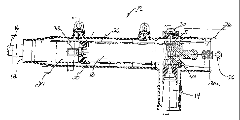
Figure 1 is a cross-sectional view of an elbow canister fuseholder of the
present invention.
Figure 2 is a cross-sectional view of the elbow interface, fuse, fuseholder
and housing
taken along sight line A-A of Figure 1.
Figure 3 is a cross-sectional view of a cable/fuse contact taken along sight
line B-B of
Figure 1.
DETAILED DESCRIPTION OF THE PREFERRED EMBODIMENT(S):
The above and other features, aspects, and advantages of the present invention
will now
be discussed in the following detailed description and appended claims, which
are to be
considered in conjunction with the accompanying drawings in which identical
reference characters
designate like elements throughout the views. Shown in Figure 1 is an elbow
canister fuseholder
10 providing a cable entrance 12 and an elbow interface 14 for mating with
suitable apparatus
bushings (not shown). It provides direct connection between a cable 16, a fuse
18 and apparatus
bushing.
3

CA 02342749 2001-04-02
The design comprises of a molded rubber sleeve 20 with its mid-section inside
diameter
supported by a rigid insulating tube 22. One end of the nibber sleeve 20 is
sized for a cable
adapter 24 that has a size sensitive inner diameter to fit various cable
diameters. The other end of
the rubber sleeve 20 is fitted for a plug 26 that is removable, allowing
accessI to the rigid tube.
The fuse 18 can pass through the plug opening 20a with clearance between the
fuse outer
diameter 22 and the inner diameter of the rigid tube 22. The plug 26 is
attached to the fuse 18 by
means of a setscrew 28, and the fuse/plug assembly can be inserted or removed
by a live linen
tool connected to an eye 30 on the plug 26. The plug 26 is fixed to the rubber
sleeve 20 by
threads in a metal contact molded into the sleeve 20 or held in place by an
external clamp. The
plug 26 provides a water and electrical seal with the sleeve: 20.
The elbow interface 14, which is preferably integral to the rubber sleeve 20,
provides a
connection means for fuseholder 10 to the fuse 18. The other end of the fuse
18 is connected to
the cable 16 through a female contact 32 that is crimped to the cable
conductor at one end, and
connected to the fuse ferrule 34 by means of an intermediaiy spring on the
other end. There is a
pulling eye 36 on the sleeve 20 that allows assembly to, anci removal from, a
bushing insert with
a live line tool.
The plug 26 can be releasably secured to the sleeve 20 by various means,
including
threads, twist lock, or external clamp.
4

CA 02342749 2001-04-02
Connection of the fuse femrle 34 to the plug contact can be via setscrews,
elbow probe
thread clamp, threads or any other adequate separable connection means that
supports the weight
of the fuse 18. The connection of the fuse ferrule 34 to the cable connector
contact can be a
garter springs, louver, pin and socket, or any other sliding connection that
allows insertion and
removal of the fuse.
The device is shown with a cable entrance and a 200A loadbreak elbow
interface. Other
interfaces can be used. A unit with two or more interfaces could be provided
with or without the
cable entrance.
The rubber sleeve 20 can be sized directly to the cable without the use of a
cable adapter.
Although the invention has been described in detail above, it is expressly
understood that
it will be apparent to persons skilled in the relevant art that ithe invention
may be modified
without departing from the spirit of the invention. Various changes of form,
design, or
arrangement may be made to the invention without departing from the spirit and
scope of the
invention. The true scope of the invention is set forth in the claims appended
hereto.
5

Representative Drawing
A single figure which represents the drawing illustrating the invention.
Administrative Status

2024-08-01:As part of the Next Generation Patents (NGP) transition, the Canadian Patents Database (CPD) now contains a more detailed Event History, which replicates the Event Log of our new back-office solution.

Please note that "Inactive:" events refers to events no longer in use in our new back-office solution.

For a clearer understanding of the status of the application/patent presented on this page, the site Disclaimer , as well as the definitions for Patent , Event History , Maintenance Fee  and Payment History  should be consulted.

Event History

Description Date
Inactive: Expired (new Act pat) 2021-04-06
Letter Sent 2021-03-01
Letter Sent 2020-08-31
Inactive: COVID 19 - Deadline extended 2020-08-19
Inactive: COVID 19 - Deadline extended 2020-08-06
Inactive: COVID 19 - Deadline extended 2020-07-16
Inactive: COVID 19 - Deadline extended 2020-07-02
Inactive: COVID 19 - Deadline extended 2020-06-10
Inactive: COVID 19 - Deadline extended 2020-05-28
Inactive: COVID 19 - Deadline extended 2020-05-14
Inactive: COVID 19 - Deadline extended 2020-04-28
Inactive: COVID 19 - Deadline extended 2020-03-29
Common Representative Appointed 2019-10-30
Grant by Issuance 2008-03-11
Inactive: Cover page published 2008-03-10
Pre-grant 2007-12-18
Inactive: Final fee received 2007-12-18
Notice of Allowance is Issued 2007-06-19
Letter Sent 2007-06-19
Notice of Allowance is Issued 2007-06-19
Inactive: Approved for allowance (AFA) 2007-05-24
Amendment Received - Voluntary Amendment 2006-10-31
Inactive: S.30(2) Rules - Examiner requisition 2006-05-02
Inactive: S.29 Rules - Examiner requisition 2006-05-02
Inactive: IPC from MCD 2006-03-12
Amendment Received - Voluntary Amendment 2003-09-18
Letter Sent 2003-08-28
All Requirements for Examination Determined Compliant 2003-08-11
Request for Examination Requirements Determined Compliant 2003-08-11
Request for Examination Received 2003-08-11
Application Published (Open to Public Inspection) 2001-10-04
Inactive: Cover page published 2001-10-03
Letter Sent 2001-07-04
Inactive: Single transfer 2001-06-04
Inactive: First IPC assigned 2001-06-01
Inactive: IPC assigned 2001-06-01
Inactive: Courtesy letter - Evidence 2001-05-08
Inactive: Filing certificate - No RFE (English) 2001-05-03
Filing Requirements Determined Compliant 2001-05-03
Application Received - Regular National 2001-05-03

Abandonment History

There is no abandonment history.

Maintenance Fee

The last payment was received on 2007-03-22

Note : If the full payment has not been received on or before the date indicated, a further fee may be required which may be one of the following

  • the reinstatement fee;
  • the late payment fee; or
  • additional fee to reverse deemed expiry.

Please refer to the CIPO Patent Fees web page to see all current fee amounts.

Owners on Record

Note: Records showing the ownership history in alphabetical order.

Current Owners on Record
THOMAS & BETTS INTERNATIONAL, INC.
Past Owners on Record
ANTHONY REED
FRANK STEPNIAK
Past Owners that do not appear in the "Owners on Record" listing will appear in other documentation within the application.
Documents

To view selected files, please enter reCAPTCHA code :


To view images, click a link in the Document Description column. To download the documents, select one or more checkboxes in the first column and then click the "Download Selected in PDF format (Zip Archive)" or the "Download Selected as Single PDF" button.

List of published and non-published patent-specific documents on the CPD .

If you have any difficulty accessing content, you can call the Client Service Centre at 1-866-997-1936 or send them an e-mail at CIPO Client Service Centre.


Document
Description 
Date
(yyyy-mm-dd) 
Number of pages   Size of Image (KB) 
Representative drawing 2001-09-14 1 20
Abstract 2001-04-02 1 17
Description 2001-04-02 5 196
Drawings 2001-04-02 1 48
Claims 2001-04-02 3 80
Cover Page 2001-09-28 1 44
Description 2006-10-31 5 199
Claims 2006-10-31 3 129
Representative drawing 2008-02-07 1 19
Cover Page 2008-02-07 1 45
Filing Certificate (English) 2001-05-03 1 164
Courtesy - Certificate of registration (related document(s)) 2001-07-04 1 112
Reminder of maintenance fee due 2002-12-03 1 106
Acknowledgement of Request for Examination 2003-08-28 1 173
Commissioner's Notice - Application Found Allowable 2007-06-19 1 165
Commissioner's Notice - Maintenance Fee for a Patent Not Paid 2020-10-19 1 549
Courtesy - Patent Term Deemed Expired 2021-03-29 1 540
Correspondence 2001-05-03 1 23
Correspondence 2007-12-18 1 31