Note: Descriptions are shown in the official language in which they were submitted.
CA 02342775 2001-06-28
METHOD OF PACKING EXTENDED REACH HORIZONTAL WELLS WITH
LIGHTWEIGHT PROPPANTS
BACKGROUND OF THE INVENTION
1. Field of the Invention
This invention relates generally to packing wells and more particularly to
method of determining combination of critical parameters including the
proppant
density, proppant concentration, proppant to liquid mix ratio, screen size,
pump
rate, and circulating pressure, which will efficiently and effectively place
the light
weight proppants over an extended segment of a highly deviated or horizontal
well, and then utilizing the selected parameters to pack the proppants in the
well.
2. Description of the Related Art
Various techniques for open hole gravel packing of oil and gas wells are
well known. Highly deviated and horizontal wells have become more common
over the past few years. Wells which include several thousand feet of
horizontal
section, some times greater than 6,000 feet, have been drilled more recently
and
many such wells are expected to be drilled in the future. Wells with such long
highly deviated or horizontal segments are referred to herein as the "extended
reach horizontal wells." Gravel or sand, which is relatively heavy (specific
gravity
of 2.65) compared to the carrying fluid (usually salt water) cannot be used
effectively for packing several thousand feet of a continuous section of
annulus
between the well and the screen. Lighter proppants, which may be made from
a variety of synthetic materials, have been used in packing the annulus of
highly
deviated wells. Extended reach open hole wells pose particular problems due
to excessive friction forces over the length of such long horizontal sections.
The
aim is to completely (100 percent) pack the annulus over the entire length of
CA 02342775 2001-06-28
-2-
the screen, which, as noted above, may be as much as 6,000 feet or more.
A horizontal open hole gravel pack is accomplished by circulating gravel
slurry into the well while keeping circulating pressures below the fracture
pressure. At the start of the gravel pack, gravel is deposited around the
screen
along the bottom of the hole building to some height at which point the
velocity
is sufficient to wash it down the hole. This process is called the Alpha wave.
When the gravel or Alpha wave reaches the bottom of the hole, gravel is then
deposited on top of the Alpha wave and the wellbore is back filled. This is
called
the Beta wave. There is a minimum circulating rate below which it is not
possible
to transport the gravel or Alpha wave completely to the end of the well.
It is not always possible to efficiently or effectively gravel pack a
horizontal open hole well with standard gravel having a specific gravity of
2.65.
But for a given Alpha wave height, a lower density gravel can be pumped at a
lower rate. It now becomes possible to one hundred percent (100%) gravel pack
a well which would not have been possible with a 2.65 specific gravity gravel.
The low weight gravel can be transported at lower rates, which reduces the
circulating pressure and keeps it below the fracture pressure.
A screen is placed along the length of the horizontal section of the well to
be packed. A mixture of the proppant and a liquid (generally sea water) is
pumped into the annulus between the screen and the well. The screen acts as
a strainer to deposit the proppant in the annulus and allows the clean fluid
to
return to the surface via a wash pipe that extends from the well bottom to the
surface.
CA 02342775 2001-06-28
-3-
Because of the extended annulus length to be packed, it is critical to
determine the various parameters that interact with each other for efficient
and
effective packing of the annulus. Such parameters include the density of the
proppant, proppant concentration, fluidlproppant mixture ("sturry"), pump
rate,
screen size, washpipe size, hydrostatic pressure, and the fracture pressure of
the formation. The inventors of this application have determined through
experiments and simulation values of the combination of the critical
parameters
that will efficiently transport the proppant to the entire extended reach of
the
annulus and effectively pack such annulus. This invention further provides a
completion string that will allow complete packing of the annulus even when a
segment of the wellbore collapses during the packing process.
SUMMARY OF THE INVENTION
The present invention provides a method for efficiently packing proppant
in open hole annulus. The method provides at least one combination of a
plurality of parameters which will provide an efficient and safe packing
operation
for extended reach horizontal open holes. For a given set of fixed parameters,
such as the wellbore size and screen size, fracture pressure, include the
proppant density, proppant and liquid mix ratio and pump rate. The wellbore
size and the screen size are initially input into a simulation program which
provides a combination of parameters that may include the total pack time for
the
Alpha wave (forward fill) and the Beta wave (back fill), the proppant density,
proppant size, proppant and liquid mix ratio, the circulating pressure profile
during packing operation. The packing operation is performed using the
parameters that will provide the most efficient and effective packing
operation.
CA 02342775 2004-O1-12
-3a-
In accordance with one aspect of the present invention there is
provided a method of packing proppant in an annulus between a wellbore and
a screen placed along a length of the wellbore, comprising:
(a) defining the approximate fracture pressure of an earth formation
surrounding the screen;
(b) defining at least one dimension of the annulus to be packed;
(c) defining at least one density parameter of the proppant;
(d) determining parameters of circulating pressure, fluid pump rate
and optimum time for substantially fully packing the annulus that
will allow packing of the annulus without fracturing the wellbore;
and
(e) packing the well in accordance with the determined parameters.
Preferably, the method further comprises determining the circulating
pressure during backfill of the annulus. It is also preferred that
determination
of the relationship includes a first relationship for forward packing and a
second relationship for backfill of the well annulus.
CA 02342775 2001-06-28
-4-
Examples of the more important features of the invention thus have been
summarized rather broadly in order that the detailed description thereof that
follows may be better understood, and in order that the contributions to the
art
may be appreciated. There are, of course, additional features of the invention
that will be described hereinafter and which will form the subject of the
claims
appended hereto.
BRIEF DESCRIPTION OF THE DRAWINGS
For detailed understanding of the present invention, references should be
made to the following detailed description of the preferred embodiment, taken
in conjunction with the accompanying drawings, in which like elements have
been given like numerals and wherein:
Figure 1 is a cross section of a horizontal well showing minimum and
maximum dune height ratios for a set of gravel pack operating parameters.
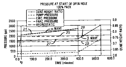
Figure 2 is a relationship of circulating pressure, fracture pressure and
the expected time for potentially packing the well configuration and
parameters
shown in Figure 1.
Figure 3 shows a cross section similar to Figure 1 for a different set of
parameters.
Figure 4 shows the pressure and time relationships for proppant packing
corresponding to the parameters shown in Figure 3.
CA 02342775 2001-06-28
-5-
Figure 5 shows a cross section similar to Figure 1 for a 6.25 inch screen
and a selected set of parameters.
Figure 6 shows the pressure and time relationships for proppant packing
corresponding to the parameters of Figure 5.
Figure 7 shows the type of input data for performing simulation to obtain
the results shown in Figures 2, 4, and 6.
Figure 8 is a line diagram of a shroud assembly for use as part of a
screen assembly.
Figure 9 is a line diagram of a screen assembly for use in a packing and
extended reach horizontal well.
DETAILED DESCRIPTION OF THE. PREFERRED EMBODIMENT
Gravel packing highly deviated wells using conventional products and
compensation techniques is extremely difficult. As well deviation increases,
pump rate and carrier fluid viscosities are increased to prevent particle
setting.
Prior art studies have shown that particle placement efficiency improves as
the
particle density "Dp" and carrier fluid density "Df' become closer. In an
ideal
system, these densities would be equal (Dp : D, = 1 ). Pack materials with
density
of 1.65 g/cc or so (which is substantially less than 2.65 glcc, the density of
sand)
have been proposed for packing wellbore annulus. It has been proposed that
lowering gravel concentration, decreasing particle diameter, decreasing
particle
density, increasing pump rate and increasing resistance to fluid flow in the
wash
CA 02342775 2001-06-28
-6-
pipelscreen annulus increases the packing efficiency. Additionally, it has
been
proposed that reducing the length of blank sections in the screen and reducing
the fluid viscosity also increase the packing efficiency. The inventors of
this
application have determined that the problems encountered in packing open hole
annulus are exacerbated in extended reach horizontal wells and that the prior
art
techniques do not provide combinations of specific values of critical
parameters
that will result in efficient and effective open hole packing. The term
"efficient"
is used herein to mean the time it takes to gravel pack a given length of the
well
annulus while the term "effective" means the degree of gravel pack. This
invention provides a more comprehensive and integrated method for determining
the valves of a set of critical parameters for efficient and effective packing
of
open hole well annulus for extended reach wells.
The inventors of the present invention have determined, through a series
of test runs, that proppant density and the screen size (particularly the
outside
diameter) are among the two most critical parameters design factors. If a
fixed
screen size is chosen, proppant density remains as the key factor in
optimizing
proppant placement. The studies were conducted to determine the critical
parameters for a 6,000 foot horizontal section. With lower density gravel the
screen size can be increased which improves the efficiency of the pack. With
a large screen less gravel is required thus the pack time can be reduced by as
much as fifty percent (50%). Table 1 below shows that for such a long
horizontal section, even certain light weight proppants are impractical for a
5.5
inch diameter screen.
This is evident from the results for the 5.5 inch screen, where it would
take twenty-three (23) hours to complete the packing, which is very
impractical.
CA 02342775 2001-06-28
-7-
However, packing of a 6-518 inch screen with the same proppant can be
accomplished in eight (8) hours. The study of Table 1 is based on: brine
weight/viscosity of 9.3 ppgl1 cp; and frac gradient of 0.659 psi/ft. In Table
1 ppg
means pounds per gallon of proppant added to the liquid and ppg means pounds
per gallon weight (density of the proppant). The term "Not Possible" indicates
that the well will fracture if the packing is attempted.
Table 1
Screen and Proppant Combination Pump Time Hydraulics
5-112" - 1 ppa Gravel 9 hours Not Possible
5-112" - 1 ppa Light Weight Proppant 9 hours Not Possible
(14 ppg)
5-1/2" - 1 ppa Light Weight Proppant 9 hours Not Possible
(12 ppg)
5-112" - 0.5 ppa Light Weight Proppant 23 hours Possible
(12 ppg)
6-518" - 1 ppa Gravel 5 hours Not Possible
6-518" - 1 ppa Light Weight Proppant 5 hours Not Possible
(14 ppg)
6-518" - 1 ppa Light Weight Proppant 5-112 hoursNot Possible
(12 ppg)
6-518" - 0.75 ppa Light Weight Proppant 8 hours Possible
(12 ppg)
Figure 1 shows the minimum and maximum dune height ratios for Alpha
waves (wave of proppant going downhole to fill the annulus). The selected
values of the critical parameters are listed in Table C of Figure 1. In Figure
1,
a screen 12 is placed along the length of the horizontal section of the well
10.
In this configuration, no centralizers are used. The screen, thus, is shown
lying
at the bottom section 13 of the well 10. A wash pipe 14 is placed inside the
screen 12 to provide a return path for the clean fluid. In Section A of Figure
1,
the annulus 11 between the screen 12 and the well 10 must be fully one hundred
percent (100%) packed with the selected proppant. The minimum and maximum
Alpha dune heights are defined by the levels 20 and 20', respectively. The
CA 02342775 2001-06-28
_$_
critical parameters used are listed in the table of Section C of Figure 1. The
screen size chosen is 5.5 inches outside diameter ("OD"), with a 4-inch OD
wash
pipe and proppant density of 14 ppg. The pump rate is 4.3 bpm, while the
proppant size is 16/30 us mesh standard.
Figure 2 shows pressure and time relationship for packing according to
the configuration and critical parameters of Figure 1. The pressure is shown
along the left vertical axis while the dune height ratio is along the right
vertical
axis. The packing time is shown along the horizontal or x-axis. The frac
pressure 25 is computed from the frac gradient of 0.659 psi/ft. During the
initial
packing, the circulating pressure 27 remains below the frac pressure 25 until
the
Alpha wave is complete, which is shown to take about 390 minutes. The
circulating pressure during the back fill (Beta wave) then starts to rise and
crosses over the frac pressure at 28. Thus, the circulating pressure exceeds
the
frac pressure until the packing is complete which is expected to take about
540
minutes. Thus this model may not be proper for packing the well as the well
may
fracture during the Beta wave.
CA 02342775 2001-06-28
_g_
Figure 3 and Figure 4 show the minimum and maximum dune heights 31
and 32 respectively and their corresponding dune height ratios when proppant
of density 12 ppg with a mix ratio of 1 ppg and pump rate of 3.6 bpm are used.
As shown in Figure 4, the circulating pressure 35 is below the frac pressure
25
throughout the Alpha wave while the circulating pressure 36 during the Beta
wave is below the frac pressure 25 until the crossover point 37 (til about
1300
minutes) and then continues to rise above the frac pressure until the
completion
of the packing process at about 1380 minutes. It is thus noted that the
packing
process is not entirely suitable with a 5.5 inch OD screen even with a
relatively
light proppant with density 12 ppg, but in many instances may be adequate to
finish the operations.
Figure 5 and Figure 6 show an example of the packing efficiency profile
for a screen with 6.625 OD for a proppant with 12 ppg density and 3.5 bpm
pump rate. The circulating pressure 41 during much of the Beta wave remains
below the frac pressure and the one hundred percent (100%) pack will be
completed in a relatively short time (about 450 minutes), which is
substantially
more efficient than the method and configuration shown in Figure 3 and Figure
4. The type of data entered into the simulation is shown in Figure 7.
In an alternative method the packing process may be carried out with two
sets of parameter values, one during the Alpha wave and the other during the
Beta wave. For example, the values of the parameters are determined that will
provide relatively fast Alpha wave operation (combination of proppant size,
mix
ratio, pump role, washpipe size etc.) and since the circulating pressure is
mainly
a problem during the Beta wave, this segment of the operation may be
CA 02342775 2001-06-28
-10-
performed using a different set of parameters that will ensure that the
circulating
pressure remains below a predetermined pressure value, typically the fracture
pressure. Thus, the present invention can provide values of the critical
parameters for different segments of the packing operation that in total will
provide the most efficient operation for one hundred percent (100%) pack.
In one mode of simulation according to the present invention, the screen
size, frac pressure, friction forces for the wellbore, carrier fluid density
or certain
other fixed parameters are provided as input and the simulation program
through
an iterative process determines the operating parameters that will provide the
most efficient packing operations for one hundred percent (100%) packing over
the entire length of the annulus. The operating parameters include (one or
more) the proppant density, proppant concentration, fluid flow or the pump
rate,
the total time for one hundred percent (100%) packing. The system also
provides the minimum and maximum Alpha wave dune heights or dune height
ratios. This allows the operator to perform the packing operations very
efficiently
and with reasonable certainty compared to the prior methods.
The results of the above-described simulation method are preferably used
with the string shown in Figure 8 and Figure 9 for packing the annulus of an
extended reach horizontal well. The annulus section or segment to be packed
with the proppant is first lined with a screen assembly 200 of sufficient
length to
cover the entire length of the horizontal well to be packed. The assembly
includes a perforated shroud 210, which is illustrated by Figure 8
independently
of the screen section 220. The shroud may be made of smaller jointed sections
211 joined at joints 212. Each individual perforated section 211 is preferably
CA 02342775 2001-06-28
-11-
approximately 90 feet long. The screen section 220, which is made by joining
individual screens 222 is disposed inside the perforated shroud 210. The
screen
section 220 may be any type that can be suitably placed inside the shroud 210.
There remains a continuous annular gap 224 between the screen section 220
and the shroud 210. This gap is sufficient to allow the packing fluid to
travel from
the top end of the screen 225 to the bottom end 226, in case the annulus
between the shroud 210 and the formation closes due to inadvertent collapse of
the formation. The perforated shroud acts as a liner between the screen 220
and the formation. The shroud is relatively thin with sufficient perforations
that
allow free flow of the proppant fluid in the annulus and is sufficiently
strong to
hold off any collapse of the formation.
The foregoing description is directed to particular embodiments of the
present invention for the purpose of illustration and explanation. It will be
apparent, however, to one skilled in the art that many modifications and
changes
to the embodiment set forth above are possible without departing from the
scope
and the spirit of the invention. It is intended that the following claims be
interpreted to embrace all such modifications and changes.