Language selection

Search

Patent 2343472 Summary

Third-party information liability

Some of the information on this Web page has been provided by external sources. The Government of Canada is not responsible for the accuracy, reliability or currency of the information supplied by external sources. Users wishing to rely upon this information should consult directly with the source of the information. Content provided by external sources is not subject to official languages, privacy and accessibility requirements.

Claims and Abstract availability

Any discrepancies in the text and image of the Claims and Abstract are due to differing posting times. Text of the Claims and Abstract are posted:

  • At the time the application is open to public inspection;
  • At the time of issue of the patent (grant).
(12) Patent Application: (11) CA 2343472
(54) English Title: VIBRATION SENSING ASSEMBLY
(54) French Title: CAPTEUR DE VIBRATIONS
Status: Deemed Abandoned and Beyond the Period of Reinstatement - Pending Response to Notice of Disregarded Communication
Bibliographic Data
(51) International Patent Classification (IPC):
  • H03K 17/94 (2006.01)
  • H01H 35/14 (2006.01)
(72) Inventors :
  • WEI, JUNG-TSUNG (Taiwan, Province of China)
(73) Owners :
  • JUNG-TSUNG WEI
(71) Applicants :
  • JUNG-TSUNG WEI (Taiwan, Province of China)
(74) Agent: SMART & BIGGAR LP
(74) Associate agent:
(45) Issued:
(22) Filed Date: 2001-04-05
(41) Open to Public Inspection: 2002-10-05
Examination requested: 2001-10-05
Availability of licence: N/A
Dedicated to the Public: N/A
(25) Language of filing: English

Patent Cooperation Treaty (PCT): No

(30) Application Priority Data: None

Abstracts

English Abstract


A vibration sensing assembly is provided which is
used as a vibration control switch while a user contacts the
vibration sensing assembly. The assembly has a manual power
switch, a power unit source, a vibration sensor, a delay
control unit, a latch control unit, a signal control unit, an
actuator and a controlled device. A vibration sensing assembly
comprising a manual switch, a power source unit, a vibration
sensor, a delay control unit, a latch control unit, a signal
control unit, an actuator, and a controlled device,
characterized in that the manual switch is connected to the
power source unit. The power source unit is connected to the
vibration sensor, the delay control unit, the latch control
unit, and the signal control unit. The delay control unit is
connected to the vibration sensor and the latch control unit.
The signal control unit is connected to the latch control unit
and the actuator. The actuator is connected to the controlled
device. The vibration sensor sends an unstable signal to the
delay control unit. The delay control unit delays the time
period of the unstable signal and sends the unstable signal to
the latch control unit. The latch control unit converts the
unstable signal into a stable signal and sends the stable
signal to the signal control unit. The signal control unit
sends the stable signal to the actuator. The actuator drives
the controlled device to operate.


Claims

Note: Claims are shown in the official language in which they were submitted.

I CLAIM:
1. A vibration sensing assembly comprising a manual
switch, a power source unit, a vibration sensor, a delay
control unit, a latch control unit, a signal control
unit, an actuator, and a controlled device, characterized
in that:
the manual switch is connected to the power source
unit,
the power source unit is connected to the vibration
sensor, the delay control unit, the latch control unit,
and the signal control unit,
the delay control unit is connected to the vibration
sensor and the latch control unit,
the signal control unit is connected to the latch
control unit and the actuator,
the actuator is connected to the controlled device,
the vibration sensor sends an unstable signal to
the delay control unit,
the delay control unit delays the time period of
the unstable signal and sends the unstable signal to
the latch control unit,
the latch control unit converts the unstable signal
into a stable signal and sends the stable signal to the
signal control unit,
the signal control unit sends the stable signal
to the actuator, and
8

the actuator drives the controlled device to
operate.
2. A vibration sensing assembly comprising a power
source unit, a vibration sensor, a filter unit, a signal
selecting unit, a microprocessor, a signal output control
unit, an actuator, and a controlled device, characterized
in that:
the power source unit is connected to the vibration
sensor, the filter unit, the signal selecting unit, the
microprocessor, the signal output control unit, and the
actuator,
the filter unit is connected to the vibration
sensor and the signal selecting unit,
the microprocessor is connected to the signal
selecting unit and the signal output control unit,
the actuator is connected to the signal output
control unit and the controlled device,
the vibration sensor sends an original signal to
the filter unit,
the filter unit filters and amplifies the original
signal and sends an amplified signal t6 the signal
selecting unit,
the signal selecting unit selects the amplified
signal and sends a stable signal to the microprocessor,
the microprocessor sends a specific signal to the
9

signal output control unit,
the output control unit sends the specific signal
to the actuator, and
the actuator drives the controlled device to
operate.
3. A vibration sensing assembly comprising a signal
emitting device and a signal receiving device,
characterized in that:
the signal emitting device has a first power source
unit, a vibration sensor, a filter unit, a coding
modulation unit, and a signal emitting unit,
the first power source unit is connected to the
vibration sensor, the filter unit, the coding modulation
unit, and the signal emitting unit,
the filter unit is connected to the vibration
sensor and the coding modulation unit,
the coding modulation unit is connected to the
signal emitting unit,
the vibration sensor sends an original signal to
the filter unit,
the filter unit filters and amplifies the original
signal and sends an amplified signal to the coding
modulation unit,
the coding modulation unit sends a coding signal
to the signal emitting unit,
10

Description

Note: Descriptions are shown in the official language in which they were submitted.


CA 02343472 2001-04-05
TITLE:VIHRATION SENSING ASSEMBLY
BACKGROUND OF THE INVENTION
The present invention relates to a vibration sensing
assembly. More particularly, the present invention relates
05 to a vibration sensing assembly which is used as a
vibration control switch.
Referring to FIG. 1, a first conventional pull-switch
has a thread 200 connected to a fluorescent lamp 100.
However, the first conventional pull-switch is easily
damaged after a long period of usage.
Referring to FIG. 2, a second conventional pull-switch
has a thread 400 connected to a lamp 300. However, the
second conventional pull-switch is easily damaged after
a long period of usage.
SUMMARY OF THE INVENTION
An object of the present invention is to provide a
vibration sensing assembly which is used as a vibration
control switch while a user contacts the vibration sensing
assembly.
BRIEF DESCRIPTION OP TFIE DRAWINGS
FIG. 1 is a perspective view of a first conventional
pull-switch of the prior art having a thread connected to
a fluorescent Lamp;
FIG. 2 is a perspective view of a second conventional
pull-switch of the prior art having a thread connected to
1

CA 02343472 2001-04-05
a lamp;
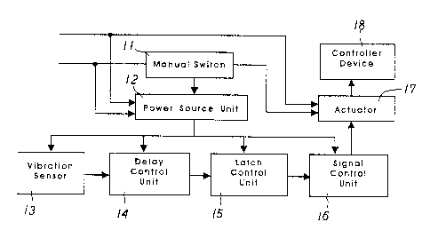
FIG. 3 is a block diagram of a first vibration
sensing assembly of a preferred embodiment in accordance
with the present invention;
05 FIG. 4 is a block diagram of a second vibration
sensing assembly of a preferred embodiment in accordance
with the present invention;
FIG. 5 is a block diagram of a third vibration
sensing assembly of a preferred embodiment in accordance
with the present invention;
FIG. 6 is a perspective view of a ball-shaped
vibration sensing assembly of a preferred embodiment
in accordance with the present invention;
FIG. 7 is a schematic view illustrating a ball-shaped
vibration sensing assembly of a preferred embodiment
disposed on a door;
FIG. 8 is a schematic view illustrating three
ball-shaped vibration sensing assembies disposed on a
lamp, a window, and a door; and
FIG. 9 is a schematic view.illustrating a helical
cord connected to a controlled device and a ball-shaped
vibration sensing assembly of a preferred embodiment.
DETAILED DESCRIPTION OF THE YNVfiNTION
Referring to FIG. 3, a first vibration sensing
assembly comprises a manual switch 11, a power source
2

CA 02343472 2001-04-05
unit 12, a vibration sensor 13, a delay control unit 14,
a latch contzol unit 15, a signal control unit 16, an
actuator 17 such as a relay, and a controlled device 18
such as a lamp and a fan.
05 The manual switch 11 is connected to the power
source unit 12.
The power source unit 12 is connected to the
vibration sensor 13, the delay control unit 14, the latch
control unit 15, and the signal control unit 16. The
delay control unit 14 is connected to the vibration
sensor 13 and the latch control unit 15. The signal
control unit 16 is connected to the latch control
unit 15 and the actuator 17. The actuator 17 is connected
to the controlled device 18.
The vibration sensor 13 sends an unstable signal to
the delay control unit 14.
The delay control unit 14 delays the time period
of the unstable signal and sends the unstable signal to
the latch control unit 15.
The latch control unit 15 converts the unstable
signal into a stable signal and sends the stable signal
to the signal control unit 16.
The signal control unit 16 sends the stable signal
to the actuator 17.
The actuator 17 drives the controlled device 18 to
3

CA 02343472 2001-04-05
operate.
Referring to FIG. 4, a second vibration sensing
assembly comprises a power source unit 21, a vibration
sensor 22, a filter unit 23, a signal selecting unit 24,
05 a microprocessor 25, a signal output control unit 26, an
actuator 27 such as a relay, and a controlled device 28.
The power source unit 21 is connected to the
vibration sensor 22, the filter unit 23, the signal
selecting unit 24, the microprocessor 25, the signal
output control unit 26, and the actuator 27.
The filter unit 23 is connected to the vibration
sensor 22 and the signal selecting unit 24.
The microprocessor 25 is connected to the signal
selecting unit 24 and the signal output control unit 26.
The actuator 27 is connected to the signal output
control unit 26 and the controlled device 28.
The vibration sensor 13 sends an original signal to
the filter unit 23.
The filter unit 23 filters and amplifies the original
signal and sends an amplified signal to the signal
selecting unit 24.
The signal selecting unit 24 selects the amplified
signal and sends a stable signal to the microprocessor 25.
The microprocessor 25 sends a specific signal to the
signal output control unit 26.
4

CA 02343472 2001-04-05
The output control unit 26 sends the specific signal
to the actuator 27.
The actuator 27 drives the controlled device 28 to
operate.
05 Referring to FIG. 5, a third vibration sensing
assembly comprises a signal emitting device 30 and a
signal receiving device 40.
The signal emitting device 30 has a first power
source unit 31, a vibration sensor 32, a filter unit 33,
a coding modulation unit 34, and a signal emitting unit
35.
The first power sou~tce unit 31 is connected to the
vibration sensor 32, the filter unit 33, the coding
modulation unit 34, and the signal,emitting unit 35.
The filter unit 33 is connected to the vibration
sensor 32 and the coding modulation unit 34.
The coding modulation unit 34 is connected to the
signal emitting unit 35.
The vibration sensor 32 sends an original signal to
the filter unit 33.
The filter unit 33 filters and amplifies the original
signal and sends an amplified signal to the coding
modulation unit 34.
The coding modulation unit 34 sends a coding signal
to the signal emitting unit 35.
5

CA 02343472 2001-04-05
The signal receiving device 40 has a second power
source unit 41, a signal receiving unit 42, a decoding
unit 43, a signal output control unit 44, an actuator 45
such as a relay, and a controlled device 46.
05 The second power source unit 41 is connected to the
signal receiving unit 42, the decoding unit 43, the signal
output control unit 44, and the actuator 45.
The decoding unit 43 is connected to the signal
receiving unit 42 and the signal output control unit 44.
The actuator 45 is connected to the signal output
control unit 44 and the controlled device 46.
The signal emitting unit 35 emits the coding signal
to the signal receiving unit 42.
The signal receiving unit 42 sends the coding signal
to the decoding unit 43.
The decoding unit 43 decodes the coding signal
and sends a decoding signal to the signal output control
unit 44.
The signal output control unit 44 sends the decoding
signal to the actuator 45.
The actuator 45 drives the controlled device 46 to
operate.
Referring to FIG. 6, a thread la is connected to a
controlled device 3a and a ball-shaped vibration sensing
Z5 assembly 2a.
6

CA 02343472 2001-04-05
Ref erring to FIG. 7, a thread 1b is connected to a
door 3D and a ball-shaped vibration sensing assembly 2b.
Referring to FIG. 8, a first thread 1 is connected
to a lamp 3 and a ball-shaped vibration sensing
05 assembly 2. A second thread 1' is connected to a window
3' and a ball-shaped vibration sensing assembly 2'.
A third thread 1 " is connected to a door 3 " and a
ball-shaped vibration sensing assembly 2 " .
Referring to FIG. 9, a helical cord 1c is connected
to a controlled device 3c and a ball-shaped vibration
sensing assembly 2c.
7

Representative Drawing
A single figure which represents the drawing illustrating the invention.
Administrative Status

2024-08-01:As part of the Next Generation Patents (NGP) transition, the Canadian Patents Database (CPD) now contains a more detailed Event History, which replicates the Event Log of our new back-office solution.

Please note that "Inactive:" events refers to events no longer in use in our new back-office solution.

For a clearer understanding of the status of the application/patent presented on this page, the site Disclaimer , as well as the definitions for Patent , Event History , Maintenance Fee  and Payment History  should be consulted.

Event History

Description Date
Inactive: IPC from MCD 2006-03-12
Application Not Reinstated by Deadline 2004-03-01
Inactive: Dead - No reply to s.30(2) Rules requisition 2004-03-01
Deemed Abandoned - Failure to Respond to Maintenance Fee Notice 2003-04-07
Inactive: Abandoned - No reply to s.30(2) Rules requisition 2003-02-28
Application Published (Open to Public Inspection) 2002-10-05
Inactive: Cover page published 2002-10-04
Inactive: S.30(2) Rules - Examiner requisition 2002-08-30
Letter Sent 2001-11-07
Inactive: Entity size changed 2001-11-07
Request for Examination Requirements Determined Compliant 2001-10-05
All Requirements for Examination Determined Compliant 2001-10-05
Request for Examination Received 2001-10-05
Inactive: First IPC assigned 2001-05-25
Inactive: Filing certificate - No RFE (English) 2001-05-09
Application Received - Regular National 2001-05-09

Abandonment History

Abandonment Date Reason Reinstatement Date
2003-04-07

Fee History

Fee Type Anniversary Year Due Date Paid Date
Application fee - small 2001-04-05
Request for examination - standard 2001-10-05
Owners on Record

Note: Records showing the ownership history in alphabetical order.

Current Owners on Record
JUNG-TSUNG WEI
Past Owners on Record
None
Past Owners that do not appear in the "Owners on Record" listing will appear in other documentation within the application.
Documents

To view selected files, please enter reCAPTCHA code :


To view images, click a link in the Document Description column (Temporarily unavailable). To download the documents, select one or more checkboxes in the first column and then click the "Download Selected in PDF format (Zip Archive)" or the "Download Selected as Single PDF" button.

List of published and non-published patent-specific documents on the CPD .

If you have any difficulty accessing content, you can call the Client Service Centre at 1-866-997-1936 or send them an e-mail at CIPO Client Service Centre.

({010=All Documents, 020=As Filed, 030=As Open to Public Inspection, 040=At Issuance, 050=Examination, 060=Incoming Correspondence, 070=Miscellaneous, 080=Outgoing Correspondence, 090=Payment})


Document
Description 
Date
(yyyy-mm-dd) 
Number of pages   Size of Image (KB) 
Representative drawing 2002-09-08 1 8
Claims 2001-04-04 3 87
Description 2001-04-04 7 197
Drawings 2001-04-04 7 73
Abstract 2001-04-04 1 38
Filing Certificate (English) 2001-05-08 1 164
Acknowledgement of Request for Examination 2001-11-06 1 179
Reminder of maintenance fee due 2002-12-08 1 106
Courtesy - Abandonment Letter (Maintenance Fee) 2003-05-04 1 176
Courtesy - Abandonment Letter (R30(2)) 2003-05-11 1 167