Language selection

Search

Patent 2343544 Summary

Third-party information liability

Some of the information on this Web page has been provided by external sources. The Government of Canada is not responsible for the accuracy, reliability or currency of the information supplied by external sources. Users wishing to rely upon this information should consult directly with the source of the information. Content provided by external sources is not subject to official languages, privacy and accessibility requirements.

Claims and Abstract availability

Any discrepancies in the text and image of the Claims and Abstract are due to differing posting times. Text of the Claims and Abstract are posted:

  • At the time the application is open to public inspection;
  • At the time of issue of the patent (grant).
(12) Patent Application: (11) CA 2343544
(54) English Title: ARRANGEMENT RELATED TO RISER PIPELINES
(54) French Title: MONTAGE POUR PIPELINES DE COLONNE MONTANTE
Status: Deemed Abandoned and Beyond the Period of Reinstatement - Pending Response to Notice of Disregarded Communication
Bibliographic Data
Abstracts

English Abstract


A device in connection with a riser for the transport of oil and/or gas,
possibly including
water, from a transport system, transport pipe (5) or similar on the sea bed
to a platform
or similar. The solution is characterised in that, in order to use a riser (1)
for the
transport of oil and/or gas from a small field with low oil/gas production
where a
transport pipe (5) with a small diameter is used, a flexible pipe (4) with
generally the
same internal diameter as the transport pipe (5) is arranged inside the riser
(1). At its
upper and lower ends, the riser (1) is provided with a coupling (6, 7), which
forms a seal
between the transport pipe (5) and the flexible pipe (4) and also forms a seal
at the ends
of the riser so that it is closed.


Claims

Note: Claims are shown in the official language in which they were submitted.

6
Claims
1. A device in connection with a riser for the transport of oil and/or gas,
possibly
including water, from a transport system, transport pipe (5) or similar on the
sea
bed to a platform or similar,
characterised in that,
in order to use a riser (1) for the transport of oil and/or gas from a small
field with
low oil/gas production where a transport pipe (5) with a small diameter is
used, a
flexible pipe (4) with generally the same internal diameter as the transport
pipe (5)
is arranged inside the riser (1), whereby at its upper and lower ends, the
riser (1)
is provided with a coupling (6, 7), which forms a seal between the transport
pipe
(5) and the flexible pipe (4) and also forms a seal at the ends of the riser
so that it
is closed.
2 A device in accordance with claim 1,
characterised in that
the seal between the flexible pipe (4) and the transport pipe (5) includes a
pipe
coupling (9) arranged in an end sealing piece (15) which is designed to be
fixed
to the riser (1).
3. A device in accordance with claim 2,
characterised in that
the end sealing piece (15) comprises a plate which is welded to the end of the
riser (1) or fixed to it by means of a flange connection (12).
4. A device in accordance with the above claims,
characterised in that
the flexible pipe (4) is perforated or permeable in some other way.

Description

Note: Descriptions are shown in the official language in which they were submitted.


CA 02343544 2001-04-09
1
The present invention concerns a device in connection with a riser for the
transport of oil
and/or gas, possibly including water, from a well head, transport pipe or
similar on the
sea bed to a platform.
Based on exploration activities in the North Sea in recent years, it seems
today as if the
era of large oil and gas finds is over. On the other hand, there have been
many finds of
a smaller size. At current oil/gas prices, they are not really commercially
attractivelprofitable, but in the future they may be interesting if oil prices
increase and/or
the technical solutions for extraction of oil become cheaper.
Many platforms which are already installed and in use have reserve risers for
future
developments. A common feature of these risers is that they were meant for
large new
fields. Their dimensions are therefore often much larger than what can be used
for
production from marginal fields with modest production and service life.
The situation is, therefore, that many risers which are held in reserve will
never be used.
In theory, it is conceivable for a transport pipe with a small diameter from a
marginal
production field to be connected directly to an existing reserve riser of a
larger diameter.
However, this is not possible as the authorities and the regulations require,
among other
things, that the riser and the production pipe can be reamed (pigged), which
can be
difficult or impossible to do at the transition from a large to a small pipe.
The alternative, therefore, is to lay a new riser which meets the statutory
requirements
for strength and installation. A new riser is, however, very expensive and
may, as
indicated above, contribute to making the development of small oil and gas
fields less

CA 02343544 2001-04-09
2
attractive to the developers. In the worst case scenario, development may be
stopped
for lack of profitability.
The present invention represents a solution which makes it possible to use
existing
reserve risers with the pressure class and strength with which such risers
were installed
and which meet the requirements of the existing regulations. The solution
makes it
possible to perform pigging and is also less expensive to install, and use
compared with
the installation of new risers.
In accordance with the present invention, the solution is characterised in
that, in order to
use a riser for the transport of oil from a small oil field with low oil/gas
production where
a transport pipe with a small diameter is used, a flexible pipe with generally
the same
internal diameter as the transport pipe is arranged inside the riser. At its
upper and lower
ends, the riser is provided with a coupling, which forms a seal between the
transport
pipe and the flexible pipe and also forms a seal at the ends of the riser so
that it is
closed.
The present invention will be described in further detail in the following
using examples
and with reference to the attached drawings, where:
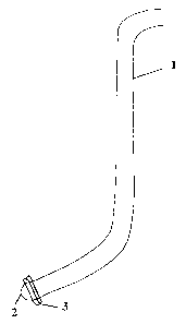
Fig. 1 shows a simple sketch of a riser.
Fig. 2 shows a similar simple sketch modified in accordance with the present
invention.
Figs. 3-5 show enlargements of three different solutions for connecting a
production
pipe to an existing riser in accordance with the present invention.
Fig. 6 shows an enlargement of an alternative embodiment with distance rings
between an internal flexible pipe and the existing riser.

CA 02343544 2001-04-09
3
As stated, Fig. 1 shows a simple sketch of a riser 1. When new platforms are
installed at
sea in connection with the development of new oil fields, the platforms (not
shown) are
provided with additional (reserve) risers 1 for use in connection with
subsequent field
developments in addition to risers which are intended for immediate use. Such
additional
risers 1 are often provided with a blinding in the form of a plug 2 or similar
at the end, for
example fixed via a flange connection 3.
The platforms are provided with the additional risers because it is not
expensive to lay
the pipes while the platform is being constructed but very expensive once the
platform
has been launched and positioned in the oil/gas field. The pipes are
classified as risers
and meet the given requirements for pressure, temperature and corrosion
resistance.
For large new oil fields, the production or transport pipe on the sea bed will
have a
diameter equivalent to that of the necessary risers on the platform so that
the transport
pipe can be connected directly to the riser. For small fields, where transport
pipes with a
smaller diameter are used, such direct connection is often not possible, as
stated above.
However, the present invention represents a solution which makes it possible
to use
existing large, available pipes. The solution is based on inserting a flexible
pipe 4, with
generally the same internal diameter as the transport pipe 5 from a near or
remote well
head underwater production plant (not shown), inside the riser 1. The
transport pipe 5 is
connected to the flexible pipe 4 via a coupling 6 at the lower end of the
riser. An
equivalent coupling 7 can be used between the flexible pipe 4 and the process
pipe
system 8 on the platform.
The coupling 6, 7 also forms a seal at the ends of the riser so that it is
closed. This
represents an important feature of the present invention, as the internal,
flexible pipe is
expediently perforated or permeable in some other way so that the oil/gas
penetrates
out into and equalises the pressure against the space (annulus) between the
flexible

CA 02343544 2001-04-09
4
pipe 4 and the riser 1. This results in the maintenance of a constant
pressure, P1 = P2
(see Fig. 5), between the annulus and the internal, flexible pipe 4. This, in
turn, results in
several advantages:
- The original reserve riser 1 is used to the full in relation to its
classification with
regard to pressure, temperature and material. Consequently, it is possible use
a
much less expensive, non-classified, flexible internal pipe 4 of various
material types
and designs.
Installation of the internal flexible pipe 4 is very simple and inexpensive
compared
with the installation of a new riser with the correct dimensions.
- It is possible to perform pigging on the flexible pipe.
Overall, therefore, the present invention represents a much simpler and less
expensive
solution than having to install a new riser with a small diameter within the
existing
qualification requirements for an existing platform.
Figures 3, 4 and 5 show alternative couplings between the transport pipe 5,
riser 1 and
flexible internal pipe 4. It is expedient to use an intermediate pipe coupling
9 between
the transport pipe 5 and the flexible pipe 4. It can advantageously be
connected to the
respective pipes by welding. The pipe coupling 9 is fixed tightly in an end
piece 15,
which, in turn, may be connected to the riser 1 by means of a weld connection
10 as
shown in Fig. 5, a sleeve clamp connection 11 as shown in Fig. 4 or a flange
connection
as shown in Fig. 3.
In connection with installation of the flexible pipe 4 in the riser 1 and
during regular
production of oil/gas for the production system, water may accumulate in the
annulus

CA 02343544 2001-04-09
between these pipes. This may expediently be sucked into the flexible pipe via
a venturi
nozzle 13, as shown in Fig. 5, to reduce potential corrosion attack.
Moreover, regarding the installation of the flexible pipe 4, it is important
that it is held in
place inside the riser, particularly in connection with pigging the pipe.
This may expediently be done using distance rings 16 arranged ,at intervals.
With regard to the expression "flexible pipe" 4, as defined in the claims,
this concerns
not only pipes which can be bent without suffering plastic deformation, but
also pipes
which are divided into sections and which are articulated. The pipe must be
able to be
pushed or drawn through a riser and adapt to the bends or curves of the riser.
Furthermore, the riser need not be a reserve riser, but may equally well be a
riser which
has previously been used for production from a large field with high
production.

Representative Drawing
A single figure which represents the drawing illustrating the invention.
Administrative Status

2024-08-01:As part of the Next Generation Patents (NGP) transition, the Canadian Patents Database (CPD) now contains a more detailed Event History, which replicates the Event Log of our new back-office solution.

Please note that "Inactive:" events refers to events no longer in use in our new back-office solution.

For a clearer understanding of the status of the application/patent presented on this page, the site Disclaimer , as well as the definitions for Patent , Event History , Maintenance Fee  and Payment History  should be consulted.

Event History

Description Date
Application Not Reinstated by Deadline 2008-04-09
Time Limit for Reversal Expired 2008-04-09
Deemed Abandoned - Failure to Respond to Maintenance Fee Notice 2007-04-10
Letter Sent 2006-04-04
Request for Examination Received 2006-03-21
Request for Examination Requirements Determined Compliant 2006-03-21
All Requirements for Examination Determined Compliant 2006-03-21
Inactive: IPC from MCD 2006-03-12
Application Published (Open to Public Inspection) 2002-10-09
Inactive: Cover page published 2002-10-08
Inactive: First IPC assigned 2001-07-12
Letter Sent 2001-06-07
Inactive: Correspondence - Transfer 2001-05-17
Inactive: Courtesy letter - Evidence 2001-05-15
Application Received - Regular National 2001-05-09
Filing Requirements Determined Compliant 2001-05-09
Inactive: Filing certificate - No RFE (English) 2001-05-09
Inactive: Single transfer 2001-05-08

Abandonment History

Abandonment Date Reason Reinstatement Date
2007-04-10

Maintenance Fee

The last payment was received on 2006-03-08

Note : If the full payment has not been received on or before the date indicated, a further fee may be required which may be one of the following

  • the reinstatement fee;
  • the late payment fee; or
  • additional fee to reverse deemed expiry.

Please refer to the CIPO Patent Fees web page to see all current fee amounts.

Fee History

Fee Type Anniversary Year Due Date Paid Date
Application fee - standard 2001-04-09
Registration of a document 2001-05-08
MF (application, 2nd anniv.) - standard 02 2003-04-09 2003-03-07
MF (application, 3rd anniv.) - standard 03 2004-04-09 2004-03-05
MF (application, 4th anniv.) - standard 04 2005-04-11 2005-03-07
MF (application, 5th anniv.) - standard 05 2006-04-10 2006-03-08
Request for examination - standard 2006-03-21
Owners on Record

Note: Records showing the ownership history in alphabetical order.

Current Owners on Record
NORSK HYDRO ASA
Past Owners on Record
HARALD ARNT FRIISK
Past Owners that do not appear in the "Owners on Record" listing will appear in other documentation within the application.
Documents

To view selected files, please enter reCAPTCHA code :


To view images, click a link in the Document Description column. To download the documents, select one or more checkboxes in the first column and then click the "Download Selected in PDF format (Zip Archive)" or the "Download Selected as Single PDF" button.

List of published and non-published patent-specific documents on the CPD .

If you have any difficulty accessing content, you can call the Client Service Centre at 1-866-997-1936 or send them an e-mail at CIPO Client Service Centre.


Document
Description 
Date
(yyyy-mm-dd) 
Number of pages   Size of Image (KB) 
Representative drawing 2002-02-18 1 2
Drawings 2001-04-09 3 37
Description 2001-04-09 5 194
Abstract 2001-04-09 1 20
Claims 2001-04-09 1 34
Cover Page 2002-09-20 1 30
Filing Certificate (English) 2001-05-09 1 164
Courtesy - Certificate of registration (related document(s)) 2001-06-07 1 112
Reminder of maintenance fee due 2002-12-10 1 106
Reminder - Request for Examination 2005-12-12 1 116
Acknowledgement of Request for Examination 2006-04-04 1 190
Courtesy - Abandonment Letter (Maintenance Fee) 2007-06-05 1 176
Correspondence 2001-05-09 1 23