Language selection

Search

Patent 2343613 Summary

Third-party information liability

Some of the information on this Web page has been provided by external sources. The Government of Canada is not responsible for the accuracy, reliability or currency of the information supplied by external sources. Users wishing to rely upon this information should consult directly with the source of the information. Content provided by external sources is not subject to official languages, privacy and accessibility requirements.

Claims and Abstract availability

Any discrepancies in the text and image of the Claims and Abstract are due to differing posting times. Text of the Claims and Abstract are posted:

  • At the time the application is open to public inspection;
  • At the time of issue of the patent (grant).
(12) Patent Application: (11) CA 2343613
(54) English Title: A CARRIAGE
(54) French Title: CHARIOT
Status: Deemed Abandoned and Beyond the Period of Reinstatement - Pending Response to Notice of Disregarded Communication
Bibliographic Data
(51) International Patent Classification (IPC):
  • A61G 07/10 (2006.01)
  • B60B 33/00 (2006.01)
  • B62B 05/00 (2006.01)
(72) Inventors :
  • VON SCHROETER, PHILIP (United Kingdom)
(73) Owners :
  • ARJO.MED.AKTIEBOLAG LIMITED
(71) Applicants :
  • ARJO.MED.AKTIEBOLAG LIMITED (United Kingdom)
(74) Agent: MARKS & CLERK
(74) Associate agent:
(45) Issued:
(22) Filed Date: 2001-04-10
(41) Open to Public Inspection: 2001-10-12
Availability of licence: N/A
Dedicated to the Public: N/A
(25) Language of filing: English

Patent Cooperation Treaty (PCT): No

(30) Application Priority Data:
Application No. Country/Territory Date
0008833.6 (United Kingdom) 2000-04-12

Abstracts

English Abstract


A carriage, such as an invalid hoist or shopping trolley, is mounted on
castors.
Each castor is swivellable about a first axis. At least one of the castors is
supported
by a support element which is angularly displaceable about a second axis
parallel to
the intended direction of fore and aft movement of the carriage. The first
axis is
perpendicular or substantially perpendicular to the second axis. Means are
provided
for angularly displacing the support element about the second axis to
encourage the
castor supported thereby to swivel one way or the other according to the
direction in
which the support element is angularly displaced and to steer the carnage when
the
latter is propelled along the ground.


Claims

Note: Claims are shown in the official language in which they were submitted.

8
What is claimed is:
1. A carriage mounted on castors, each of which is swivellable about a first
axis,
at least one of the castors being supported by a support element which is
angularly
displaceable about a second axis parallel to the intended direction of fore
and aft
movement of the carriage, said first axis being perpendicular or substantially
perpendicular to said second axis, and means being provided for angularly
displacing
said support element about said second axis to encourage the castor supported
thereby
to swivel one way or the other according to the direction in which the support
element
is angularly displaced and to steer the carriage when the latter is propelled
along the
ground.
2. A chassis as claimed in claim 1, wherein the displacing means comprises a
manually operable lever.
3. A carriage as claimed in claim l, wherein the displacing means comprises a
power driven actuator.
4. A carriage as claimed in claim 1, wherein the carnage is in the form of a
chassis comprising a pair of parallel spaced apart elongate chassis members
connected
together by at least one cross member, each chassis member supporting two
castors
swivellable about respective first axes, one of the chassis members forming
the

9
support element for two of said castors and being angularly displaceable about
said
second axis which also extends in the direction of the longitudinal extent of
said one
chassis member.
5. A carriage as claimed in claim 4, wherein the chassis member is angularly
displaceable through a first angle to steer the chassis and through a second
larger
angle to facilitate movement of the one chassis member towards or away from
the
other chassis member.
6. A carriage as claimed in claim 4, wherein said one chassis member is
mounted
for said angular displacement in a bearing supported directly or indirectly by
the said
at least one cross member.
7. A carriage as claimed in claim 1, in the form of an invalid hoist.
8. An invalid hoist as claimed in claim 7, further comprising a first
telescopically
extendible/retractable mast upstanding from the other chassis members, a
second
telescopically extendible/retractable mast upstanding from the other chassis
member,
each mast having an upper part and a lower part, the cross member being in the
form
of a lifting arm supported by and extending between the first and second
masts, and
power operated means for extending and retracting the first and second masts
in
synchronism with one another.

10
9. An invalid hoist as claimed in claim 8, wherein the lifting arm maintains
the
two chassis members in spaced apart parallel or substantially parallel
relationship.
10. An invalid hoist as claimed in claim 8, wherein the lifting arm is the
sole
means connecting the first mast and chassis member to the second mast and
chassis
member.
11. An invalid hoist as claimed in claim 8, wherein the lifting arm can be
raised
or lowered relative to the masts.
12. An invalid hoist as claimed in claim 8, wherein the lifting arm comprises
two
parts pivotable relative to one another about a vertical or substantially
vertical axis,
one part being supported by the first mast and the other part being supported
by the
second mast.
13. An invalid lifting device as claimed in claim 12, wherein each part of the
lifting arm comprises a parallelogram linkage to maintain the chassis members
in
parallel spaced relationship as the two parts of the arm pivot relative to one
another.
14. A carriage as claimed in claim 1, in the form of a shopping trolley.

Description

Note: Descriptions are shown in the official language in which they were submitted.


CA 02343613 2001-04-10
2
INTRODUCTION
This invention relates to a carriage, particularly a steerable carriage such
as
an invalid hoist or shopping trolley.
SUMMARY OF THE INVENTION
According to the present invention there is provided a carriage mounted on
castors, each of which is swivellable about a first axis, at least one of the
castors
being supported by a support: element which is angularly displaceable about a
second
axis parallel to the intended direction of fore and aft movement of the
carnage, said
first axis being perpendicular or substantially perpendicular to said second
axis, and
means being provided for angularly displacing said support element about said
second
axis to encourage the castor supported thereby to swivel one way or the other
according to the direction in which the support element is angularly displaced
and to
steer the carriage when the latter is propelled along the ground.
The invention will now be more particularly described, by way of example,
with reference to the accompanying drawings.

CA 02343613 2001-04-10
3
BRIEF DESCRIPTION OF THE DRAWINGS
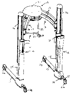
Figure 1 is a perspective view of a carnage according to the present
invention,
in the form of an invalid hoist,
Figure 2 is an end view of one of the chassis members of the hoist shown in
Figure 1, in a first condition,
Figure 3 is a view similar to Figure 2 with the chassis member in a second
condition,
Figure 4 is a view similar to Figure 2 with the chassis member in a third
condition,
Figure 5 is a view similar to Figure 2 with the chassis member in a fourth
condition,
Figure 6 is a fragmentary perspective view showing the chassis member and
lower part of the mast with the chassis member in said first or third
condition, and
Figure 7 is a view similar to Figure 6 but with the chassis member in said
second or fourth condition.

CA 02343613 2001-04-10
4
DESCRIPTION OF THE PREFERRED EMBODIMENTS
Referring now to the drawings, the carriage shown therein is in the form of
an invalid hoist comprising a first telescopically extendible/retractable mast
10
upstanding from a first elongate chassis member 11 and a second telescopically
extendible/retractable mast 12 upstanding from a second elongate chassis
member 13.
Each mast has an upper part 14 and a lower part 15.
A lifting arm 16 is supported by and extends between the upper parts 14 of the
first and second masts 10 and 12, respectively. The lifting arm 16 comprises
two
parts 17 and 18 pivotable relative to one another in a horizontal plane. The
part 17
is supported by the upper part 14 of the first mast 10 and the part 18 is
supported by
the upper part of the second mast 12. The lifting arm 16 is the sole means
connecting
the first mast 10 and the chassis member 11 to the second mast 12 and the
chassis
member 13.
Each part 17 and 18 of the lifting arm comprises a parallelogram linkage 19
to maintain the chassis members 11 and 12 in parallel spaced relationship as
the two
parts 17 and 18 of the arm 16 pivot relative to one another and a carriage 20
which
is mounted on the upper part 14 of the mast.
The upper mast parts I 4 telescope over the lower mast parts 15 . The
carriages

CA 02343613 2001-04-10
20 can be raised or lowered relative to the upper mast parts 14 in addition to
being
raised and lowered by relative movement of the two mast parts 14, 15 to
increase the
overall lifting range of the lifting device. A power operated actuator (not
shown) is
provided in each mast for extending and retracting the two masts, and for
raising and
5 lowering the two carriages, in synchronism with one another.
An actuator (not shown) is accommodated in housing 21 for angularly
displacing the two parts 17 .'and 18 of the lifting arm relative to one
another.
A sling hanger 22 for supporting a full body sling is suspended from the
lifting arm 16 by a sling hanger support 23. The sling hanger 22 is pivotable
relative
to the sling hanger support 'Z3 about a horizontal axis.
Each chassis has two castors 24 swivellable about an in use vertical axis 25.
The castors 24 are shown in Figure 1 in positions which result in the chassis
moving
in a straight line if propelled manually along the ground in for or aft
direction.
The chassis member 13 is supported in a bearing 30 at the base of the lower
part 15 of the mast 12 for angular displacement about an in use horizontal
axis 26
extending in the direction of the longitudinal extent of the chassis member
13.
The chassis member 13 is angularly displaceable in the bearing 30 by a lever

CA 02343613 2001-04-10
6
31. Alternatively, it could be pivotable by a motor and gearbox unit (not
shown)
housed in the base of the lower part 15 of the mast 12.
The chassis member 13 is pivoted through an angle «, typically in the region
of 5 °, in an anti-clockwise direction, as viewed in Figures 2 to 6 to
encourage the
castors 24 supported by the chassis member 13 to swivel to the position as
shown in
Figure 2 in order to steer the chassis to the left when the latter is
propelled along the
ground. The chassis member 13 is angularly displaced through a similar angle «
in
a clockwise direction, as viewed in Figures 3 and 7, in order to encourage the
castors
to swivel to the position as shown in Figures 3 and 7 in order to steer the
chassis to
the right when the latter is propelled along the ground.
The chassis member 13 can be angularly displaced through a larger angle Vii,
typically in the region of 1 S", as shown in Figure 4 and 5 to facilitate the
movement
of the chassis member 13 towards or away from the chassis member 11 when the
two
parts of the lifting arm are pivoted relative to one another to reduce or
increase the
width of the chassis.
Although, as described above, a chassis member and two castors are pivotable
about the axis 26, it is conceivable that a single castor and support element
therefor
are pivotable about an axis parallel to the intended direction of fore and aft
movement
of the carnage to encourage that castor to steer the carnage when the latter
is

CA 02343613 2001-04-10
7
propelled along the ground.
The carriage as described above has been described in the form of a particular
type of lifting hoist. The carriage could be in the form of other types of
lifting hoist
and in particular in the form of lifting hoists in which the two chassis
members are
connected together by a fixed or telescopically extendible cross member at the
base
of the hoist. The carnage a~uld take other forms and, in particular, could be
in the
form of a shopping trolley.

Representative Drawing
A single figure which represents the drawing illustrating the invention.
Administrative Status

2024-08-01:As part of the Next Generation Patents (NGP) transition, the Canadian Patents Database (CPD) now contains a more detailed Event History, which replicates the Event Log of our new back-office solution.

Please note that "Inactive:" events refers to events no longer in use in our new back-office solution.

For a clearer understanding of the status of the application/patent presented on this page, the site Disclaimer , as well as the definitions for Patent , Event History , Maintenance Fee  and Payment History  should be consulted.

Event History

Description Date
Inactive: IPC from MCD 2006-03-12
Application Not Reinstated by Deadline 2005-04-11
Time Limit for Reversal Expired 2005-04-11
Deemed Abandoned - Failure to Respond to Maintenance Fee Notice 2004-04-13
Letter Sent 2003-05-16
Letter Sent 2002-04-25
Amendment Received - Voluntary Amendment 2002-03-13
Inactive: Single transfer 2002-03-13
Application Published (Open to Public Inspection) 2001-10-12
Inactive: Cover page published 2001-10-11
Inactive: IPC assigned 2001-06-04
Inactive: First IPC assigned 2001-06-04
Inactive: Courtesy letter - Evidence 2001-05-22
Inactive: Filing certificate - No RFE (English) 2001-05-14
Application Received - Regular National 2001-05-10

Abandonment History

Abandonment Date Reason Reinstatement Date
2004-04-13

Maintenance Fee

The last payment was received on 2003-03-27

Note : If the full payment has not been received on or before the date indicated, a further fee may be required which may be one of the following

  • the reinstatement fee;
  • the late payment fee; or
  • additional fee to reverse deemed expiry.

Patent fees are adjusted on the 1st of January every year. The amounts above are the current amounts if received by December 31 of the current year.
Please refer to the CIPO Patent Fees web page to see all current fee amounts.

Fee History

Fee Type Anniversary Year Due Date Paid Date
Application fee - standard 2001-04-10
Registration of a document 2002-03-13
MF (application, 2nd anniv.) - standard 02 2003-04-10 2003-03-27
Registration of a document 2003-04-01
Owners on Record

Note: Records showing the ownership history in alphabetical order.

Current Owners on Record
ARJO.MED.AKTIEBOLAG LIMITED
Past Owners on Record
PHILIP VON SCHROETER
Past Owners that do not appear in the "Owners on Record" listing will appear in other documentation within the application.
Documents

To view selected files, please enter reCAPTCHA code :


To view images, click a link in the Document Description column. To download the documents, select one or more checkboxes in the first column and then click the "Download Selected in PDF format (Zip Archive)" or the "Download Selected as Single PDF" button.

List of published and non-published patent-specific documents on the CPD .

If you have any difficulty accessing content, you can call the Client Service Centre at 1-866-997-1936 or send them an e-mail at CIPO Client Service Centre.


Document
Description 
Date
(yyyy-mm-dd) 
Number of pages   Size of Image (KB) 
Representative drawing 2001-09-16 1 11
Abstract 2001-04-09 1 19
Claims 2001-04-09 3 88
Description 2001-04-09 6 160
Drawings 2001-04-09 4 80
Filing Certificate (English) 2001-05-13 1 164
Request for evidence or missing transfer 2002-04-10 1 108
Courtesy - Certificate of registration (related document(s)) 2002-04-24 1 114
Reminder of maintenance fee due 2002-12-10 1 106
Courtesy - Abandonment Letter (Maintenance Fee) 2004-06-07 1 175
Correspondence 2001-05-13 1 22