Note: Descriptions are shown in the official language in which they were submitted.
CA 02343670 2008-01-16
METHOD OF CLEANING AN OZONE GENERATOR
FIELD OF THE INVENTION
The present invention is related to a method for cleaning electrical discharge
ozone
generators. More particularly, the present invention relates to circulating a
warm fluid
within the ozone generator to evaporate solid deposits of nitrogen oxides,
including
dinitrogen pentoxide, from the tubes and dielectrics of the generator.
BACKGROUND TO THE INVENTION
Ozone (03) is a strong oxidizing agent (2.07V) that is used as a disinfectant
in
various applications, such as wastewater treatment, cooling towers, air
treatment, swimming
pool cleaning, food processing, hydroponics, and meat processing. Ozone is
particularly
effective in aqueous environments. Ozone is, however, very reactive and cannot
be stored
for any significant period of time. As a result, ozone must be generated at
the site where it
is to be used. Two common means by which ozone is generated are by subjecting
oxygen
gas (02) to ultraviolet radiation or to an electrical discharge.
One type of electrical discharge generator is an electrical barrier discharge
ozone
generator, commonly known as a silent discharge generator. One such generator
is a corona
discharge generator. Corona discharge generators are commonly used to generate
ozone on
a large scale. The basic principle of electrical discharge ozone generators is
that a feed gas
is fed through a high voltage electrical discharge field between two
electrodes. The oxygen
is then ionized as it passes through the electrical field which will cause at
least some oxygen
1
CA 02343670 2008-01-16
to be converted to ozone. For corona discharge generators, the feed gas,
usually dry air or
oxygen, is subjected to coronal discharges created by high voltages between
two electrodes,
one of which is contained within a dielectric material. In a tubular ozone
generator, a
dielectric is supported within a tube and a central cathode within the
dielectric is subjected
to a high voltage relative to an outer anode. The anode is often grounded.
High voltage
phenomena occur inside the dielectric envelope and induce a corona discharge
field
between the outside of the dielectric envelope (hereinafter referred to as
"dielectric") and
the outer anode material. An oxygen-containing feed gas is fed into this space
and through
this field, and the oxygen (02) molecules are split to form atomic oxygen,
which then reacts
to form ozone.
302 + Energy -> 203 (Eq. 1)
The quantity of ozone generated depends on several factors, such as for
example the
voltage, the frequency of AC current, the gap between the dielectric and the
cathode and the
concentration of 02 and other gases in the feed gas. The feed gas may be dry,
clean air; dry,
clean oxygen; or dry, clean oxygen containing small amounts of other
relatively inert gases
such as nitrogen (N2) or argon (Ar). It is important that dry feed gas be
used, as water
interferes with the reaction and also reacts with gases in the ozone gas to
create
contaminants, most notably nitric acid (HNO3).
Much of the energy required for the reaction is lost as heat; therefore ozone
generators should be cooled to operate more efficiently. One of the ways that
cooling the
generator increases the efficiency of the generator is by causing fewer 03
molecules to be
lost due to decomposition or collision. A good description of ozone generating
equipment
2
CA 02343670 2008-01-16
can be found in U.S. Patent 4,954,321 by Jensen issued September 4, 1990, and
also in
"Ozone Technology and Equipment Design", Ozonia North America, USA 1996.
Large amounts of ozone are not easily generated. For example, an ozone
generation
system employing an electrical discharge and which uses liquid oxygen at
_99.5% purity,
that has been vaporized and has had between 2 and 3% N2 by weight and a
certain amount
of argon added, will typically produce 10 - 13% ozone by weight. Because of
the relatively
low rate of ozone generation, large plants may require several ozone
generators to meet the
demand for ozone. In turn, each generator may contain many
anode/cathode/dielectric
units.
As noted above, the amount of ozone generated depends on several factors, one
of
which is the amount of N2 in the feed gas. When oxygen separated from air is
used as a
feed gas, nitrogen may be present. This is because of the method used to
separate the
oxygen from the air, e.g. vacuum or pressure swing adsorption or cryogenic
separation.
Nitrogen may also be present in the feed gas because it has been introduced to
act as a
catalyst. Nitrogen allows production of a higher ozone concentration or the
reduction of the
power consumed in generating the ozone. For example, large commercial ozone
generators
using pure oxygen generally create between 6 - 10% ozone by weight, instead of
the 10 -
13% available when a small amount of N2 is added. It is therefore not
desirable to remove
all of the N2.
Unfortunately, it has been discovered that the presence of nitrogen in the
feed gas
results in a solid residue, mainly composed of dinitrogen pentoxide (N205),
with some of it
being deposited within the generator system, including on the tubes and the
dielectrics. The
3
CA 02343670 2008-01-16
residue may also contain other solid oxides of nitrogen (NYOx). The oxide
deposits on the
support tubes and dielectrics and may eventually clog the passageway between
the dielectric
and the support tube.
Regular maintenance of ozone generators typically involves an inspection and
repair
of the electrical connections. However, because of the problems inherent in
cleaning the
generators described in greater detail below, opening the ozone generator to
the atmosphere
is avoided whenever possible. From time to time, however, ozone generators may
require
special or preventative maintenance. Such maintenance may be occasioned by
failure of
more than approximately 10% of the dielectrics or by deposits that clog the
passages
between the dielectrics and their support tubes in some systems.
Current methods of cleaning ozone generators consist of turning off the power
supply and cooling water and purging the generator by circulating dry oxygen
gas at room
temperature through the system. The purging continues until the residual ozone
has been
removed from the inside of the generator for the safety of the workers.
Thereafter the
system is opened up to the atmosphere.
When the ozone generator is opened for regular maintenance, if it is opened
for long
enough, the water in the ambient air reacts with any residual solid nitrogen
oxides to form
nitric acid (HNO3). The reaction with N205 for example, proceeds as follows:
H20 + N205 -> 2 HNO3 (Eq, 2)
Nitric acid is an oily, yellow residue, and any nitric acid in the generator
needs to be
removed.
4
CA 02343670 2008-01-16
The cleaning typically requires that all dielectrics and the tubes holding
them be
cleaned with a proper solvent. Generally, the dielectrics and tubes are
removed from the
system, cleaned with water and then with an industrial organic solvent such as
acetone or a
chlorinated organic solvent such as perchloroethylene, or methanol. This
cleaning work is
time consuming, and may require more than 14 days for an industrial scale
ozone generator.
In addition, removal and cleaning of the dielectrics will result in some
breakage (perhaps
10%), thereby requiring their replacement. Finally, the chlorine containing
solvents and the
disposal of the contaminated cleaning solvents represent additional cost and
safety issues
that must be considered.
It is therefore desirable to have a less onerous cleaning method that would
decrease
the time and expense required for special maintenance of electrical discharge
ozone
generators, particularly large-scale corona discharge ozone generators.
SUMMARY OF THE INVENTION
The current invention relates to a method of removing solid deposits of the
oxides of
nitrogen, including in particular dinitrogen pentoxide, in an ozone generator
thereby
avoiding the need to open the generator to atmosphere. If it is necessary to
open the
generator, to replace dielectrics for example, the inventive method will
significantly reduce
or eliminate the creation of nitric acid residue within the system. The
inventive method can
significantly reduce the maintenance time required from perhaps two to three
weeks for
each generator to perhaps as little as three days. In addition, damage to the
dielectrics is
minimized or eliminated, as is the need for solvents to remove the nitric
acid. The method
can provide significant costs savings in personnel time and materials.
5
CA 02343670 2008-01-16
A preferred embodiment of the inventive method uses warm gas circulation,
preferably at 47-65 C, within the generator dielectric support tubes and warm
water
circulation in the shell section of the generator, preferably at 47-65 C. If
the physical
components of the generator can withstand temperatures above 65 C then the
temperature
of the gas can be increased well above 65 C, although this is not necessary to
remove
dinitrogen pentoxide, and heating the gas to a higher temperature may make the
cleaning
process more expensive. The fluid circulation within the system raises the
temperature
within the generator, and various solid oxides of nitrogen, which have boiling
points less
than the temperature of the circulated gas, including dinitrogen pentoxide
which has a
boiling point of about 47 C, are evaporated and thereafter evacuated from the
system by the
gas stream. The temperature within the generator is sufficient to ensure that
the deposits do
not re-form within the ozone generator.
The progress of the cleaning can be monitored by bubbling a portion of the
evacuated gas through a water trap and measuring the change in pH caused by
the HNO3
formed by interaction of the NyOX and the water. Fluids are circulated within
the generator
until the pH of the water used as a reference is not appreciably lowered by
the gas exiting
the tubes of the generator.
If the need for maintenance was caused only by a build-up of NYO, including in
particular N205, the system is ready to return to production without requiring
the generator
to be opened to the atmosphere. Cleaning time and potential contamination are
reduced. If
the maintenance was required because of damaged dielectrics, when the system
is opened to
ambient air after being sufficiently cleaned, no nitric acid is formed. Only
those dielectrics
6
CA 02343670 2008-01-16
requiring replacement need be removed and replaced. Again, there are
significant benefits
in terms of both time and material savings.
In one aspect of the invention there is provided a method of cleaning an
electrical
discharge ozone generator comprising passing a warm cleaning gas between an
inlet of the
generator and an outlet of the generator to evaporate at least some of the
NYO,, deposited in
the ozone generator.
In another aspect of the invention there is provided a method for removing
solid
deposits of NYO, from an ozone generator comprising first and second
electrodes, the
electrodes being spaced from each other and having a passageway therebetween.
The solid
deposits of NYO, are located within the passageway. The method comprises the
step (i) of
passing a warm cleaning gas through the passageway to evaporate the solid
deposits of
NYO, with boiling points equal to or less than 65 C which are deposited
therein. The warm
cleaning gas exiting the ozone generator is at a temperature sufficient to
maintain the NyOX
in a gaseous state until the NYO, exits the ozone generator.
In another aspect of the invention there is provided a method for removing
solid
deposits of NyOX from an ozone generator comprising a housing enclosing an
interior
having an inlet and an outlet and a pair of spaced electrodes mounted within
the interior.
The electrodes are spaced apart from each other. The solid deposits of NyOX
are located
within the interior. The method comprises the step of passing a warm cleaning
gas through
the interior from the inlet to the outlet to evaporate at least some of the
NYO, deposited
therein. The warm cleaning gas exits the ozone generator at a temperature
sufficient to
maintain the NyOX in a gaseous state until the NYO, exits the ozone generator.
7
CA 02343670 2008-01-16
In a further aspect of the invention there is provided a method for removing
solid
deposits of NyOX from an ozone generator comprising a housing and a plurality
of support
tubes mounted within the housing. The support tubes each support one or more
dielectrics
and each of the support tubes has an inner wall. A passageway is formed
between the inner
wall of the support tubes and the dielectrics. The passageway has solid
deposits of NyOX
therein. A support tube inlet is in flow communication with a support tube
outlet through
the passageway. The method comprises the step (i) of passing a warm cleaning
gas through
the passageway to evaporate at least some of the solid deposits of NyOX which
are deposited
therein and carry at least some of the evaporated NyO,t from the ozone
generator.
In another aspect of the invention there is provided a method for removing
solid
deposits of NyOX from an ozone generator comprising an outer housing and a
plurality of
support tubes mounted within the housing. The support tubes each support one
or more
dielectrics and each of the support tubes has an inner wall and a passageway
between the
inner wall and the dielectrics. The passageway communicates between a support
tube inlet
and a support tube outlet. The housing has a shell that defines an interior
surrounding the
support tubes, the interior communicates between a shell inlet and a shell
outlet. The
method comprises step (i) of circulating a warm fluid within the shell and the
concurrent
step (ii) of evacuating the support tubes to remove the evaporated NyOX with
boiling points
less than 65 C that had been deposited therein.
In a further aspect of the invention there is provided a method for removing
solid
deposits of NyOX from an ozone generator comprising an outer housing and a
plurality of
support tubes mounted within the housing. The support tubes each support one
or more
dielectrics and each of the support tubes has an inner wall and a passageway
between the
8
CA 02343670 2008-01-16
inner wall and the one or more dielectrics. The passageway communicates
between a
support tube inlet and a support tube outlet. The housing has a shell that
defines an interior
surrounding the support tubes. The interior communicates between a shell inlet
and a shell
outlet. The method comprises step (i) of circulating a cleaning gas within the
support tubes
and concurrent step (ii) of circulating a warm fluid within the shell to heat
the cleaning gas,
thereby removing the NyO,{with boiling points less than 65 C deposited
therein. The
temperature of the warm fluid is sufficient to ensure that the temperature of
the cleaning gas
exiting the ozone generator is sufficient to maintain the NyO,t in a gaseous
state until the
NyOx exits said ozone generator.
In yet another aspect of the invention there is provided a method for removing
dinitrogen pentoxide deposits from an ozone generator comprising an outer
housing and a
plurality of support tubes mounted within the housing. The support tubes each
support one
or more dielectrics and each support tube has an inner wall and a passageway
between the
inner wall and the dielectrics. The passageway communicates between a support
tube inlet
and a support tube outlet. A shell surrounds the support tubes, the shell
defining an interior
surrounding the support tubes. The interior communicates between a shell inlet
and a shell
outlet. The method comprises circulating a clean, dry mixture of oxygen,
nitrogen and
argon at 55 C - 60 C between the shell inlet and shell outlet; supplying the
shell with warm
water at 55 C - 60 C; diverting a portion of the gas exiting the support tubes
to a liquid ring
compressor; adding a neutralizing agent to the water in the compressor to
maintain the pH
in the liquid ring compressor at an approximately constant pH using an in-line
process pH
controller; and continuing the cleaning until the addition of neutralizing
agent terminates as
it is no longer required to maintain the constant pH.
9
CA 02343670 2008-01-16
Other aspects and features of the present invention will become apparent to
those
ordinarily skilled in the art upon review of the following description of
specific, preferred
embodiments of the invention in conjunction with the accompanying figures.
BRIEF DESCRIPTION OF THE DRAWINGS
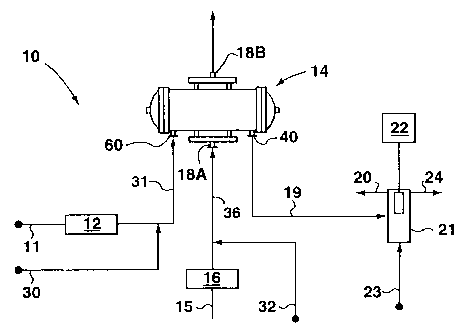
Fig. I is a schematic representation of an ozone generating system having an
ozone geneator
which can be cleaned using a method in accordance with an embodiment of the
invention.
Fig. 2 is a cross-sectional view of part of an ozone generator, that can be
cleaned using an
embodiment of the inventive method.
Fig. 3 is a cross-sectional view at 3-3 of Fig. 2.
DETAILED DESCRIPTION OF THE PREFERRED EMBODIMENTS
With reference to Figs. 1, 2 and 3, an ozone generator system 10 is
illustrated which
includes an ozone generator 14. It will be appreciated that Figures 2 and 3
show only part
of an ozone generator. Typically such electrical discharge generators employ
numerous
dielectric support tubes through which oxygen is passed during the ozone
generation
process.
In the Figures, generator 14 has a housing formed from a shell 14A. In this
case, it
is shown in Figures 1 and 2 with a jacket 14B surrounding shell 14A, although
a jacket is
not typically employed in commercial generators. Between shell 14A and jacket
14B is a
jacket passageway 54. The jacket 14B has an inlet (not shown) which is in flow
communication with an outlet (not shown) through passageway 54. Shell 14A
houses a
CA 02343670 2008-01-16
plurality of dielectric support tubes 28 which are mounted on supports within
the interior 34
of shell 14A. Between the support tubes in interior 34 is an interior space 35
which
surrounds the support tubes. Each support tube 28 houses one or more
dielectrics 27. Each
tube 28 has an inlet 25 which is in flow communication with an outlet 26
through a
passageway 33 which is provided between the inner wa1150 of the support tube
28 and the
outer wall 52 of the dielectrics 27. In operation to make ozone, ozone is
created in the
corona electrical discharge immediately outside or around dielectric 27.
During the
production of ozone, deposits 29 of nitrogen oxides, especially N205, may
build up on the
dielectric 27 and the inner wall support tube 28.
The system 10 also provides for cool water to flow through the interior space
35 of
generator shell 14A around the tubes 28. During operation of system 10 to
produce ozone,
the flowing water will cool generator 14, thereby increasing the efficiency of
ozone
production. The flow of water 17A enters inlet (shown schematically as 18A) of
shell 14A
via conduit 36 and exits at outlet (shown schematically 18B). The water fills
interior space
35, which as described above generally comprises the portion of interior 34 of
the housing
not filled by support tubes 28. However, when used in the inventive method of
cleaning,
the water flowing through interior space 35 is warm and may be provided by
water source
15 and heated at heater 16 or water may be provided by a source of warm water
32.
Also, during operation of system 10 to produce ozone, gas enters the ozone
generator 14 at inlet 60 through conduit 31 (Figure 1), and then the gas flow
divides within
the generator 14 so that a portion of the total gas flow will flow through
each of the
passageways between the inlets and outlets of each support tube. At the
outlets 26 of each
support tube 28, the separate flows re-unite and then exit the generator at a
common outlet
11
CA 02343670 2008-01-16
40. Providing a positive flow of gas is also preferred in practicing the
inventive method.
Thus during the cleaning process, a flow of gas 13A enters support tubes 28 at
each inlet 25
and exits at each outlet 26. The cleaning gas may be provided by gas source 11
and heated
at heater 12 or gas may be provided by gas source 30, which is already heated.
After
travelling through support tubes 28, the cleaning gas exits shell 14A via
outlet 40 and may
enter a water trap 21 via conduit 19. A portion of the cleaning gas that exits
outlet 40 is
diverted to outlet 20. Water trap 21 is provided with a source of reference
water 23, and a
pH monitor 22. Water exits water trap 21 through exit 24.
When ozone production is stopped at installation 10 to undertake special
maintenance, occasioned, for example, by the support tubes 28 being plugged,
such as by
solid deposits of N205 and perhaps other solid oxides of nitrogen in
passageway 33 or by
too many of the dielectrics 27 being damaged, the system is first purged of
all 03. This can
be done, for example, by using the feed gas generally used to create ozone or
by using
industrial grade oxygen. The gas is fed through support tubes 28 while no
electric discharge
is present.
With reference to Figs. 1-3, after purging the generator of ozone, in one
embodiment
of the invention, the inside of generator 14 where the dielectrics 27 and
support tubes 28 are
located is supplied through inlet 25 with a warm cleaning gas. The cleaning
gas may be any
dry, clean gas that is compatible with the ozone generator system, such as
oxygen; nitrogen;
a mixture of nitrogen and oxygen that may contain argon; or industrial grade
helium, argon,
air or possibly even carbon dioxide (C02), although the latter will have the
effect of
lowering the pH to 7.0-8Ø It may be most convenient to utilize oxygen since
that is the gas
used in the ozone generating process. The cleaning gas must be dry,
sufficiently
12
CA 02343670 2008-01-16
contaminant-free and compatible with a system used for generating ozone, i.e.
it should not
detrimentally affect the physical system or interfere with production of ozone
when the
system is returned to production. Any such gas should be dry or substantially
dry. In this
embodiment, the cleaning gas evaporates and entrains the NyOX 29 deposited on
the
dielectrics 27 and support tubes 28.
Herein, the term "cleaning gas", when used in this specification and claims
includes
any of the cleaning gases described thus far in the specification, and any
other suitable
gases.
In one preferred embodiment, the cleaning gas 11 is circulated into inlet 25
via
conduit 31 and inlet 60 after heating at heat source 12 which may be any
conventional heat
source, for example, a water bath, or an electrical or steam heater. In
another preferred
embodiment, a source of hot gas 30 may also be used. The gas enters the
support tube 28 at
inlet 25 at a temperature of preferably between 47 - 65 C and most preferably
55 - 60 C.
The cleaning gas exits support tube 28 at outlet 26. Cleaning gas is
circulated through the
system 10 until the solid deposits of NyO, that have boiling points of about
65 C or less,
including in particular N205, have been substantially removed from the ozone
generator.
The temperature of the warm gas 19A that exits tube 28, and later outlet 40,
is
preferably between 47 - 65 C to ensure that the evaporated NyOX does not re-
deposit as
solids within the ozone generator. While not strictly necessary, it is good
practice to ensure
that NyOX also does not re-deposit within conduit 19.
13
CA 02343670 2008-01-16
In the same preferred embodiments, while the gas is circulating in tube 28,
water is
circulated in the interior 34 of generator shell 14A. In one such preferred
embodiment, the
circulating water 15 is heated before entering the interior space 35 of shell
14A via conduit
36 and inlet 18A using a conventional heat source 16. As stated above, the
heat source
may, for example, be a water bath or an electrical or steam heater. In another
embodiment,
a source of warm water 32 is used. The water enters interior space 35 at inlet
18A at a
temperature of between 29 - 65 C, preferably between 47 - 65 C and most
preferably
between 55 - 60 C and exits at outlet 18B at a temperature sufficient to
ensure that, in
combination with the cleaning gas temperature, the evaporated NYO,, remains in
a gaseous
state until it exits outlet 40.
While water circulation is preferred, it is not necessary. In most
applications, gas
circulation alone, should normally be sufficient to clean the system of the
NyOX deposits as
long as the temperature reached inside the support tubes is sufficient to
evaporate the NyOX
29, as the gas passes over the NyOX solids 29 and maintain the NyOX in a
gaseous state until
the NyO, exits the generator 14. It will also be appreciated that, at
relatively high flow rates
of cleaning gas, the NyOX solids may be evaporated at a temperature that is
significantly
below their boiling points due to the vapor pressure effects.
In yet a further embodiment, the gas 13A or water 17A may be heated after
entering
the generator 14 by causing the generator itself to be heated. Such heating
may take many
forms, such as for example by applying a heat source directly to the outside
of shell 14A or
by circulating hot water or steam through a jacket 14B mounted on the outside
of shell 14A,
as long as the generator can withstand such heating.
14
CA 02343670 2008-01-16
Additionally, in a further embodiment of the invention there is no need to
heat the
cleaning gas directly if the temperature and the effect of the fluids
circulating in interior
space 35 or jacket 14B has a sufficient effect on heating the cleaning gas,
that the cleaning
gas can evaporate substantially all of the deposited NyOx 29 and maintain the
NyOX in a
gaseous state until it exits the generator 14 at outlet 40.
Additionally, it may also possible to remove the deposits of NyOX 29 using
water
circulation only in generator shell 14A, as long as the temperature inside the
support tubes
28 of the generator 14 is sufficient to evaporate the NyOX deposit 29.
However, if this
embodiment of the invention is used, a means for creating a flow of gas out of
support tube
28, such as a vacuum pump will be required. In that case, the ozone generator
used must be
rated to withstand the physical stresses that may result.
If warm water is used, it exits generator shell 14A at outlet 18B. The water
exiting
generator shell 14A has a temperature of preferably between 47 - 65 C. The
water may be
discharged in an environmentally safe manner or it may be re-circulated to
inlet 32 if it is
still warm although more likely it would be returned to inlet 15 and reheated
prior to re-
circulation through the generator.
In a further embodiment of the invention, at least a portion of the cleaning
gas
exiting support tube 28 through outlet 26 enters a water trap 21 via conduit
19. The pH of
the water in water trap 21 is monitored continuously or manually by a pH meter
22. The
water trap 21 may be any one of several water containers such as a barrel, a
tank or a liquid
ring compressor, as long as it is sufficiently stable to withstand the
expected gas flow into
the water. The liquid ring compressor uses an elliptical liquid ring around an
impeller to
CA 02343670 2008-01-16
compress the ozone gas. As the ozone is compressed, it gives off heat, but
this heat is
absorbed by the ring of water. This water is continuously re-circulated
through the
compressor and through a heat exchanger to cool the water.
The majority of the gas exits outlet 20 in front of water trap 21 to an
approved
scrubbing or capture system.
If NyO,, 29, including in particular N205, is present, it will react with
reference water
23 flowing into the trap 21 and form nitric acid, thereby reducing the pH 24
of the water in
the trap 21 below that of the incoming reference water 23.
The reference water 23 is fed into the trap 21 continuously at a certain flow
rate,
which will depend on the particular system being cleaned, sufficient to record
an
appreciable pH change at the beginning of the cleaning cycle when the cleaning
gas and
warm water are at the proper temperature. The value of the appreciable pH
change will
depend on the pH monitoring system being used. The pH may also be monitored
manually.
The value of the pH drop can be approximately 3 pH units. The water trap 21
may be any
size. The pH is allowed to vary and is monitored. When the monitored pH
returns to the
same pH as the incoming water, and stays constant, the cleaning will have been
completed.
In the preferred embodiment, the existing installation liquid ring compressor
21 and
in-line pH control system, which includes a pH meter, are used to monitor the
pH 24 of the
water containing gas from conduit 19. When a compressor is used, it is not
desirable to
allow the pH to vary significantly as that might damage the compressor.
Therefore, the
method employed is that when the cleaning first begins, the pH of the
reference water 23 in
16
CA 02343670 2008-01-16
the liquid ring compressor 21 will start to drop. In response, the in-line pH
control system
starts to add a neutralizing agent, for example, trisodium phosphate (TSP), to
maintain the
pH at a substantially stable level. Thus the presence of nitric acid can be
ascertained by
whether or not the neutralizing agent is continuing to be added. When the
addition of the
neutralizing agent stops, (i.e. no neutralizing agent is needed because the
incoming gas no
longer contains significant amounts of N,,O,, and therefore no nitric acid is
formed) the
cleaning is complete.
The circulation of warm gas 13A and/or warm water 17A is maintained until
substantially all NyOX 29 with boiling points less than 65 C, especially N205,
have been
removed from support tube 28 and dielectric 27 of the generator. Typically,
this is when
there is no longer an appreciable difference in pH between the pH 24 of the
water exiting
the trap 21 and the pH of the reference water 23 entering the trap 21, if no
pH adjustment is
applied.
It will be appreciated by those skilled in the art, however, that pH
monitoring, or
more generally monitoring for the presence of NyOx in the cleaning gas, is not
necessary for
the generator cleaning to be effectual. The cleaning may also be carried out
for particular
periods of time for which it is known that sufficient cleaning will have
occurred, rather than
monitoring. However, monitoring will clearly be a more accurate way of
ensuring that the
generator has been cleaned sufficiently.
It will be appreciated by those skilled in the art that while water has been
used to
describe the above embodiments, other fluids including gases may be used
within interior
17
CA 02343670 2008-01-16
34 and jacket 14B as long as they are compatible with the physical
characteristics of the
ozone generator being used.
The aforementioned temperature ranges are influenced by the physical
characteristics, including partially the boiling points of the NyO, 29, and
the physical limits
of the particular generator used. The upper temperature limit of 65 C may be
increased in
generators that are constructed to withstand elevated temperatures. The upper
limit of the
temperature range is then dictated by other concerns such as safety concerns.
In the preferred embodiment, the 03 is purged from the system before the
generator
cleaning process is started. However, if the ozone generating plant has
available means of
disposing of water contaminated with 03, the cleaning procedure can be
commenced
without first performing the 03 purge.
The foregoing description is necessarily described with reference to the
preferred
embodiments of the inventive method applied to a particular ozone generator
system but of
course, the method may also be applied to other ozone generating apparatus.
For example,
the ozone generator may consist of spaced apart electrodes that are electrode
plates and that
have a passageway therebetween. While a plurality of embodiments of this
invention has
been illustrated in the accompanying drawings and described above, it will
also be evident
to those skilled in the art that changes and modifications may be made therein
without
departing from the invention. All such modifications or variations are
considered to be
within the scope of the invention as defined by the claims appended hereto.
18