Note: Descriptions are shown in the official language in which they were submitted.
CA 02343886 2001-03-13
ELASTIC ENDLESS CRAWLER
FIELD OF THE INVENTION
The present invention relates to a ring-shaped elastic endless
crawler which comprises an elongated belt-shaped elastic crawler body,
and a plurality of cords disposed in array and embedded in the crawler
body so as to extend in a longitudinal direction of the crawler body, in
which each of cord protruding portions projecting out from one end of
the crawler body, and a corresponding cord protruding portion
projecting out from another end of the crawler body are made to overlap
each other and the cord protruding portions are entirely subjected to
vulcanization processing to thereby form an integrally connected
structure.
BACKGROUND ART
A conventional rubber crawler 1 will be hereinafter described
with reference to Figs. 1 to 4.
In a manufacturing process of the rubber crawler 1, first, as
illustrated in Fig. 3, a semi-manufactured product is formed in which
steel cords 3 are made to project out from each of one end la of a
crawler body and another end lb of the crawler body by the same
length.
Next, as illustrated in Fig. 4, each of cord protruding portions
3a at the one end 1 a of the crawler body, and a corresponding cord
protruding portion 3b at the another end lb of the crawler body are
1
CA 02343886 2001-03-13
disposed so as to overlap each other. Lines A0 - A0, and BO - B0 each
connecting opposite ends of cord protruding portions, are arranged in
parallel in a transverse direction of a belt and extend transversely of an
entire width of the belt. For the purpose of facilitating understanding,
in Fig. 4, a portion in which cord protruding portions overlap each other
is indicated exaggeratively by a thick line.
Due to the cord protruding portions 3a and 3b being entirely
subjected to vulcanization processing (heating and filling unvulcanized
rubber), an integrated rubber crawler as shown in Figs. 1 and 2 is
completed.
However, the rigidity of the rubber crawler 1 depends on the
steel cords 3, and a portion of the crawler body including a region in
which steel cords 3 overlap each other, necessarily becomes higher in
rigidity (becomes very hard) than a portion cif the crawler body not
including the region in which the steel cords 3 overlap each other.
Accordingly, when the rubber crawler 1 is used in a state of
being fitted around a sprocket or an idler (which are not shown), a state
is caused in which a hard portion and a non-hard portion of the rubber
crawler 1 are intermittently engaged with each other. As a result,
vibration or noise may be unavoidably generated.
Further, the lines A0 - A0 and BO - BO which form the boundary
between a high-rigidity (hard) portion and a nonrigid portion of the
rubber crawler 1 are straight lines each extei:id transversely of an entire
width of the crawler body (that is, the belt). Therefore, the rubber
crawler 1 is easy to considerably bend with the lines AO - A0 and BO -
2
CA 02343886 2001-03-13
BO substantially as the center.
DISCLOSURE OF THE INVENTION
One object of the present invention is to provide a structure by
which a difference in rigidity between a portion of a crawler body
including a region in which steel cords overlap each other, and a
portion of the crawler body not including the region, can be reduced as
far as possible, thereby preventing generation of vibration or noise.
Further, another object of the preser.it invention is to provide a
rubber crawler having excellent durability and reliability, in which a
boundary between a high-rigidity portion and a nonrigid portion of the
rubber crawler is formed characteristically to alleviate occurrence of
bending or buckling of the rubber crawler.
In order to solve the above-described problems, an elastic
endless crawler of the present invention is a ring-shaped elastic endless
crawler which comprises an elongated belt-shaped elastic crawler
body, and a plurality of cords disposed in a:rray and embedded in the
crawler body so as to extend in a longitudinal direction of the crawler
body, in which each of cord protruding portions projecting out from
one end of the crawler body and a corresponding cord protruding
portion projecting out from the other end of the crawler body are made
to overlap each other, and thereafter, are eritirely subjected to
vulcanization processing to thereby form an. integrally connected
structure, the elastic endless crawler being characterized in that cord
protruding portions at each of the ends of the crawler body are divided
3
CA 02343886 2001-03-13
into groups such that each group has a protruding length different
from those of other groups.
Another elastic endless crawler according to the present
invention is characterized in that the entire cord protruding portions at
the one end of the crawler body when seen from a direction
perpendicular to a belt surface, are formed so as to present a male
configuration, and the entire cord protruding portions at the other end
of the crawler body are formed so as to present a female configuration.
Still another elastic endless crawler according to the present
invention is characterized in that lines each connecting ends of facing
cord protruding portions at the ends of the crawler body are disposed so
as to have a configuration that is one of terraced, tiered, and
crenellated when seen from a direction perpendicular to a belt surface.
A further elastic endless crawler according to the present
invention is characterized in that when seen from a direction
perpendicular to a belt surface, a portion ir.i which cord protruding
portions overlap each other, includes two outlines separated from
each other in a longitudinal direction of a belt, and each outline
includes a bent line.
BRIEF DESCRIPTION OF THE DRAWINGS
Fig. 1 is a cross-sectional side view which shows a connecting
portion in a conventional rubber crawler.
Fig. 2 is a plan view of the rubber crawler shown in Fig. 1.
Fig. 3 is a plan view which shows cord protruding portions at
4
CA 02343886 2001-03-13
each of ends of a crawler body in a connecting process of the rubber
crawler shown in Fig. 1.
Fig. 4 is a plan view which shows a state in which each of the
cord protruding portions shown in Fig. 3 and a corresponding cord
protruding portion are made to overlap each other.
Fig. 5 is a cross-sectional side view which shows a connecting
portion in a rubber crawler according to a first embodiment of the
present invention.
Fig. 6 is a plan view of the rubber crawler shown in Fig. 5.
Fig. 7 is a plan view which shows cord protruding portions at
each of ends of a crawler body in a connecting process of the rubber
crawler shown in Fig. 5.
Fig. 8 is a plan view which shows a state in which each of the
cord protruding portions shown in Fig. 7 and a corresponding cord
protruding portion are made to overlap each other.
Fig. 9 is a plan view of a rubber crawler according to a second
embodiment of the present invention.
Fig. 10 is a plan view which shows cord protruding portions at
each of ends of a crawler body in a connecting process of the rubber
crawler shown in Fig. 9.
Fig. 11 is a plan view which shows a state in which each of the
cord protruding portions shown in Fig. 10 and a corresponding cord
protruding portion are made to overlap each other.
BEST MODES FOR CARRYING OUT THE INVENTION
CA 02343886 2001-03-13
Referring now to the attached drawi:ngs, the present invention
will be hereinafter described in conjunction with a plurality of
embodiments. It should be understood that the present invention
should not be limited to the embodiments. For example, a rubber
crawler according to these embodiments is a so-called internal driving
type rubber crawler, but the present invention is not limited to the
same.
First, a first embodiment of the present invention will be
described with reference to Figs. 5 to 8.
As shown in Figs. 5 and 6, the rubber crawler 11 of the first
embodiment includes an elongated belt-shaped elastic crawler body,
and a plurality of cords 13 made of, for example, steel, which are
disposed in array and embedded in the crawler body so as to extend in
a longitudinal direction of the crawler body. A plurality of protrusions
17 for driving the rubber crawler are formed at an underside of the
rubber crawler (belt), that is, on an inner peripheral surface of the
crawler.
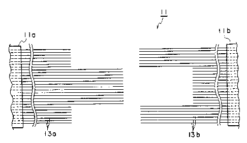
As shown in Fig. 7, in a rubber craw:ler manufacturing process
(in a connecting process), a semi-manufactured product is prepared in
which cords 13 (13a and 13b) are respectively made to project out from
one end 11a of the crawler body and the other end 11b of the crawler
body, and the cords are disposed so as to face each other.
Subsequently, as shown in Fig. 8, each of cord protruding
portions 13a at the one end 11 a of the crawler body and a
corresponding cord protruding portion 13b at the other end l lb of the
6
CA 02343886 2001-03-13
crawler body are disposed so as to overlap each other. For the purpose
of facilitating understanding, portions in which corresponding cord
protruding portions overlap each other, are indicated exaggeratively by
thick lines.
Due to the cord protruding portions 13a and 13b being entirely
subjected to vulcanization processing (heatir.Lg and filling unvulcanized
rubber), a rubber crawler product having an integrally connected
structure as shown in Figs. 5 and 6 is completed.
A structural feature of the present e:mbodiment is that, as
shown in Fig. 7, the cord protruding portions 13a and 13b at the ends
11a and 1 lb of the crawler body are divided into groups such that each
group has a protruding length different from those of other groups.
Specifically, when seen from a direction perpendicular to a belt
surface, the cord protruding portions at the one end 11 a of the crawler
body has, as a whole, a convex configuration (a male configuration),
and the cord protruding portions at the other end 1 lb of the crawler
body has, as a whole, a concave configuration (a female configuration).
In other words, the lines which each connect ends of facing
cord protruding portions at the ends of the crawler body are disposed so
as to have one of terraced, tiered, and crenellated configurations.
As can be seen from Fig. 8 which shows the overlapping state,
the cord overlapping portion includes outline (Al-Al'-Al) and outline
(Bl-B1'-B1).
The above-described outlines are separated from each other in
a longitudinal direction of the belt (that is, a longitudinal direction of
7
CA 02343886 2001-03-13
the crawler body). Each outline is comprised of a bent line, not one
straight line.
Due to the above-described structural feature of the present
embodiment, the difference in rigidity between a portion of the crawler
body including the overlapping portion, and a portion thereof not
including the overlapping portion becomes s:mall as compared with the
conventional rubber crawler 1. Namely, the portion of the crawler body
including the overlapping portion is not so hard.
Accordingly, a problem of high noise or high vibration
generated in the conventional rubber crawler is completely settled. It is
considered that this is because the overlapping portion in which high
rigidity may be caused, is partially offset (dis:persed) in the longitudinal
direction of the belt.
Further, the outline (A l-A 1'-A l) and the outline (B 1-B l'-B l),
which form the boundary between the high-rigidity portion and the
nonrigid portion of the rubber crawler 11, are neither a straight line.
Therefore, as compared with the conventional rubber crawler, bending
of the rubber crawler 11 with the above-described outlines
substantially as the center, is difficult to occur.
Referring again to Figs. 6 and 8, a dimension H between
position Bl and an intermediate position of position Al' and position
Bl' (which intermediate position is position P1) in the longitudinal
direction of the belt is preferably 10 mm or greater, and more preferably
20 mm or greater. When the dimension H is lless than 10 mm or 0 mm,
buckling is apt to occur very often in an intermediate portion of the
8
CA 02343886 2001-03-13
rubber crawler including the overlapping portion.
Next, a description will be given, witli reference to Figs. 9 to 11,
of a rubber crawler 21 according to a second embodiment of the present
invention, mainly, a portion in which the second embodiment differs
from the first embodiment.
In the second embodiment, as can be seen from Fig. 11 which
shows the overlapping state, a portion in which cord protruding
portions 23a and 23b overlap each other, includes outline (A2-A2'-
A2"-A2'-A2) and outline (B2-B2'-B2"-B2'-B2).
The above-described outlines are separated from each other in
the longitudinal direction of the belt, and each outline is comprised of a
bent line, not one straight line. In other words, the lines which each
connect ends of facing cord protruding portions at ends 21 a and 21b of
the crawler body, are disposed so as to have one of terraced, tiered, and
crenellated configurations.
Due to the above-described structural feature of the second
embodiment, the same effect as that of the first embodiment, or more
excellent effect can be obtained. That is, a portion of the crawler body
including the overlapping portion does not become hard, and bending
of the rubber crawler with the outlines substantially as the center is
difficult to occur.
Referring again to Fig. 11, from the standpoint of preventing
occurrence of buckling, it is preferable that the intermediate position
between position A2" and position B2" in the longitudinal direction of
the belt does not coincide with position B2 or position B2'.
9
CA 02343886 2001-03-13
In each of the first and second embodiments, when the rubber
crawler is used, there is a risk of ends of cord protruding portions (at
position B 1' of Fig. 6 and position B" of Fig. 9) projecting out from the
crawler body made of rubber. Accordingly, desirably, cords may be
embedded into the crawler body so that the ends of cord protruding
portions be located at positions in which the ends and the driving
rubber protrusion 17 and 27 overlap each other. As a result, the
above-described drawback can be avoided.
Further, any of the cord protruding portions at the ends of the
crawler body may be positioned at the side of inner periphery (or outer
periphery) of the rubber crawler.
INDUSTRIAL APPLICABILITY
As described above, according to the: present invention, the
differen-ce in rigidity between a connecting portion of the crawler body
and a portion thereof not including the connecting portion can be
lessened, and occurrence of bending or buckling in the connecting
portion can be prevented. As a result, a rubber crawler having excellent
durability and reliability can be provided.