Note: Descriptions are shown in the official language in which they were submitted.
CA 02343889 2008-07-16
WO 00/15284 PCTIUS99/21225
IMPROVED RESPIRATORY SUCTION CATHETER APPARATUS
BACKGROUND OF THE INVENTION
1. Field of the Invention
The present invention relates to an respiratory suction catheter system with
an
improved mechanism for cleaning the tip of the catheter without drawing an
excessive
amount of air from the respiration circuit to which the endotracheal catheter
is attached.
More specifically, the present invention relates principally to a closed
suction endotracheal
catheter system which provides improved cleaning of the catheter while
minimizing or
eliminating air drawn from the patient's respiration circuit.
2. State of the Art
There are a variety of different circumstances under which a person may be
required
to have an artificial airway, such as an endotracheal tube, placed in his or
her respiratory
system. In some circumstances, such as surgery, the artificial airway's
function is primarily
to keep the patient's airway open so that adequate lung ventilation can be
maintained during
the procedure. In many other situations, however, the endotracheal tube will
be left in the
patient for a prolonged period of time. For example, with many patients, the
endotracheal
tube will remain in place to sustain mechanical ventilation for the life of
the patient.
If an endotracheal tube is to be left in place for any substantial amount of
time, it is
critical that respiratory secretions be periodically removed. This is most
often accomplished
with the use of a respiratory suction catheter. As the suction catheter is
withdrawn, a
negative pressure is applied to the interior of the catheter to draw mucus and
other secretions
from the respiratory system. While a substantial amount of the mucus and other
secretions
will be withdrawn through the catheter lumen, a portion of the mucus and other
secretions
remain on the outside of the catheter. Because patient secretions can contain
infectious
diseases, such as streptococcus, pseudomonas, staphylococcus and even HIV, it
is important
to shield clinicians from them. Likewise, it is important to shield the
patients from
communicable pathogens in the environment. This is particularly important
because such
patients often have compromised immune systems.
In addition to concems of cross-contamination, suctioning patients' artificial
airways
I
! I I
CA 02343889 2001-03-13
WO 00/15284 PCT/US99/21225
potentially interferes with proper respiration. The most common group of
patients who have
indwelling endotracheal tubes for prolonged periods are those who must be
mechanically
ventilated. Mechanically ventilated patients will typically have a fitting or
manifold attached
to the proximal end of the endotracheal tube (i.e. the end extending outside
the patient) at an
endotracheal tube hub. A pair of ventilator tubes extend from a mechanical
ventilator and
are typically attached to the manifold by an adapter. One tube provides
inspiratory air to the
patient for inhalation. The other tube allows for exhaled or expiratory air to
exit the system.
Until the 1980s, it was common to disconnect the patient from the manifold and
ventilator tubes each time the patient needed to be suctioned. Interference
with the air supply
to the patient, even if only for a few seconds, was often unnecessarily
distressing to the
patient. These problems were initially overcome in ~the invention disclosed in
U.S. Patent
No. 3,991,762 to Radford. Radford developed whait is commonly referred to as a
closed
suction catheter system. In a closed suction catheter system, a catheter is
maintained within
a protective sleeve which is attached to the manifold. When suctioning is
desired, the
catheter is advanced through the manifold and into the artificial airway.
Negative pressure
is then applied to the catheter and secretions within the patients respiratory
system are
evacuated. Improvements were made to the system by the invention disclosed in
U.S. Patent
No. 4,569,344 to Palmer. Palmer improved the system by reducing the risk of
cross-
contamination between the patient and the medical personnel using the device.
Since that
time, there has been a significant shift toward the use of closed suction
catheter systems.
The advantage of closed suction catheters is that the ventilating circuit is
not detached
from the patient during suction procedures, as it is during open suction
procedures.
Because the catheter is reused a number of tirnes over a twenty-four hour
period, it
is important that mucus and other secretions be cleaned from the catheter
prior to periods of
non-use. If the secretions are not removed, the risk of auto-contamination
increases. It is
also important to clean the lumen of the catheter to rr.-aintain suction
efficiency.
There are several mechanisms by which the catheter may be cleaned. First, in
U.S.
Patent No. 4,569,344, there is shown a lavage port which enables the user to
inject liquid into
the area surrounding the distal end of the catheter after it has been
withdrawn from the
patient. When liquid is injected into the closed suction catheter apparatus
and suction is
applied, the liquid helps to loosen and remove the secretions from the
exterior of the catheter.
2
CA 02343889 2001-03-13
WO 00/15284 PCTIUS99/21225
One significant problem with simply injecting liquid and applying suction to
remove
it, is that the suction also causes a volume of respiratory air to be removed
through the
catheter. In a "closed system", the air that is evacuated potentially disrupts
the carefully
controlled ventilatory cycles. Thus, the amount of respiratory air available
to the patient is
potentially decreased as a result of catheter cleaning. If the clinician has a
hard time cleaning
secretions from the catheter, suction may be applied through the catheter
several times -
thereby repeatedly drawing air from the ventilatory circuit.
Other closed suction catheters have been developed to have a cleaning or
lavage
chamber which is physically isolated from the respiration circuit. For
example, in U.S. Patent
No. 5,487,381 to Jinotti, there is shown a closed suctiion catheter which has
a lavage chamber
configured to receive the distal tip of the catheter as it is withdrawn from
the manifold. A
wall is then slid from an open position to a closed position to isolate the
distal end. of the
catheter from the manifold and the respiration circuit. A port is commonly
provided to inject
lavage solution into the cleaning chamber.
One problem which is present in such a configuration is that there is a lack
of air to
allow suction catheter to clean properly. The application of negative pressure
in the catheter
can create a vacuum within the chamber in the absence of sufficient air flow
into the
chamber. Thus, isolating the chamber inhibits free evacuation of the cleaning
solution.
Further, in one presently available product, the cleaning liquid commonly
remains in the
catheter due to the lack of airflow. Thus, contaminated liquids remaining in
the catheter
lumen can be reintroduced to the patient when the cleaning chamber is opened.
In addition to the above concerns, the closed suction catheters presently
available
suffer from the inability to clean the catheter tip to the most desirable
extent. If pathogens
or other contaminants remain on the catheter for too long, they can auto-
contaminate the
patient. Additionally, if mucus and other secretions dry on the catheter, they
can interfere
with the suction efficiency, present an unsightly ;appearance and necessitate
premature
replacement of the closed suction catheter apparatus. Thus, there is a need
for a catheter
apparatus which has a mechanism for more effectively cleaning the 'distal end
of the catheter
without creating a substantial draw on respiratory air in the ventilation
circuit.
SUMMARY OF THE INVENTION
3
CA 02343889 2001-03-13
WO 00/15284 PCT/US99/21225
Thus, it is an object of the present invention to provide an improved
respiratory
suction catheter apparatus which minimizes the amount of air drawn from the
ventilation
circuit during cleaning of the distal end of the catheter.
It is another object of the present invention to provide such a respiratory
suction
catheter apparatus which improves removal of mucus and other secretions from
the distal tip
of the catheter.
It is yet another object of the present invention to provide such a
respiratory suction
catheter apparatus wherein the mechanisms for improving cleaning function
automatically
to separate a cleaning chamber from the ventilation circuit.
It is still another object of the present invention to provide such a
respiratory suction
catheter apparatus which causes cleaning to be effected in a turbulent fluid
flow.
It is a further object of the present invention to provide such a respiratory
suction
catheter apparatus which is easy to use and relatively inexpensive.
The above and other objects of the invention are realized in specific
illustrated
embodiments of an improved respiratory suction catheter apparatus which
includes a
manifold for attachment to an artificial airway, suclh as an endotracheal
tube, to form a
ventilation circuit, a catheter which is displaceable through the manifold and
into the
artificial airway to suction secretions from the artii:iciai airway and lungs,
and a valve
mechanism disposed adjacent the ventilation circuit to minimize the air drawn
from the
respiration circuit of a patient while the catheter is being cleaned.
In accordance with one aspect of the invention, the valve mechanism is
configured
to automatically engage the catheter tip after it is withdrawn through the
manifold to thereby
minimize the amount of air drawn into the catheter during cleaning.
In accordance with another aspect of the present invention, the valve
mechanism is
provided with an air makeup to allow makeup air into Tthe catheter and thereby
ensure proper
evacuation of secretions, and any liquid used to clean the catheter.
In accordance with another aspect of the present invention, an air turbulence
enhancing mechanism is provided for increasing turbulent airflow around the
distal end of
the catheter to thereby improve removal of secretions from the catheter.
In accordance with still another aspect of the present invention, an air
makeup
mechanism is disposed so as to provide makeup air to the distal end of the
catheter which is
4
CA 02343889 2001-03-13
WO 00/15284 PCT/US99/21225
not drawn from the ventilation circuit.
BRIEF DESCRIPTION OF THE DRAWINGS
The above and other objects, features and advantages of the invention will
become
apparent from a consideration of the following detailed description presented
in connection
with the accompanying drawings in which:
FIG. 1 shows a cross-sectional view of a mani:fold and catheter cleansing
mechanism
in accordance with the teachings of the prior art;
FIG. 2 shows a cross-sectional view of a manifold and catheter cleaning
mechanism
in accordance with the teachings of another embodinient of the prior art;
FIG. 3A shows cross-sectional view of the r.nanifold and catheter of an
improved
respiratory suction catheter apparatus with a valve member in an open position
in accordance
with the principles of the present invention;
FIG. 3B shows a cross-sectional view of the manifold and catheter shown in
FIG. 3A,
with the valve in a second, closed position;
FIG. 3C shows a fragmented, close-up cross-sectional view of one embodiment of
the
improved respiratory suction catheter apparatus shown in FIG. 3A;
FIG. 3D shows a fragmented, close-up cross-sectional view of another
embodiment
of the improved respiratory suction catheter apparatus shown in FIG. 3A;
FIG. 3E shows a cross-sectional view of an e;mbodiment similar to those shown
in
FIGs. 3A through 3D, but wherein the flap engages the collar;
FIG. 4A shows a fragmented, cross-sectional view of an alternate embodiment of
an
improved respiratory suction catheter apparatus having a valve in an open
position in
accordance with the principles of the present invention;
FIG. 4B shows a fragmented, cross-sectional view of the embodiment of FIG. 4A,
wherein the valve is in a closed position to isolate the catheter from the
ventilation circuit;
FIG. 4C shows a fragmented, cross-sectional view of the embodiment of FIGs. 4A
and 4B, with an air makeup mechanism in an open position to facilitate
suctioning of mucus
and the like;
FIG. 5A shows a cross-sectional view of an alternate embodiment of an improved
respiratory suction catheter apparatus having a valve in an open position in
accordance with
5
CA 02343889 2001-03-13
WO 00/15284 PCT/US99/21225
the principles of the present invention;
FIG. 5B shows a cross-sectional view of the eimbodiment shown in FIG. 5A with
the
valve in a closed position;
FIG. 5C shows a partial cross-sectional view of the valve of the embodiment
shown
in FIGs. 5A and 5B;
FIG. 6A shows a cross-sectional view of yet another altemative embodiment of
an
improved respiratory suction catheter apparatus made in accordance with the
principles of
the present invention;
FIG. 6B shows a cross-sectional view of the embodiment shown in FIG. 6A in a
closed configuration;
FIGs. 6C and 6D show end views of the valve mechanism of the embodiment shown
in FIGs. 6A and 6B in a relaxed position and with a catheter extending
therethrough,
respectively;
FIG. 7A shows a cross-sectional view of still, another embodiment of an
improved
respiratory suction catheter apparatus made in accordance with the principles
of the present
invention;
FIG. 7B shows a partial end view of the iimproved respiratory suction catheter
apparatus of FIG. 7A in a closed position;
FIG. 8A shows a cross-sectional view of still yet another embodiment of an
improved
respiratory suction catheter apparatus made in accordance with the principles
of the present
invention; and
FIG. 8B shows a cross-section view of the improved endotracheal catheter of
FIG.
8A, wherein the valve mechanism is in a closed configuration.
DETAILED DESCRIPTION
Reference will now be made to the drawings in which the various elements of
the
present invention will be given numeral designatior.is and in which the
invention will be
discussed so as to enable one skilled in the art to make and use the
invention. It is to be
understood that the following description is only exernplary of the principles
of the present
invention, and should not be viewed as narrowing the pending claims.
6
CA 02343889 2001-03-13
WO 00/15284 PCT/US99/21225 _
Referring to FIG. 1, there is shown a cross-sectional view of a manifold 10
and
catheter cleansing mechanism 14 in accordance with the teachings of the prior
art. The
manifold 10 has a valve mechanism in the form of a rotatable rod 18 for
selectively isolating
a lavage chamber 20 from the ventilation circuit 26. When the distal end of
the catheter 22
is disposed in the lavage chamber 20, a lavage solution can be injected
through a side port
30 to help wash the mucus and other secretions from the exterior of the
catheter 22. Because
of the relative size and dimensions of the lavage clu-unber 20, however, there
is nothing to
force vigorous interaction between the lavage solution and the secretions on
the exterior of
the catheter. Additionally, because the lavage chamber is not configured for
makeup air to
enter when the rotatable rod 18 is closed, a vacuum can be created in the
lavage chamber 20
which interferes with effective suctioning.
An additional disadvantage of the embodiment shown in FIG. 1 is that the
closure
mechanism for such devices must typically be manually activated. If the user
fails to close
the rotatable rod 18, actuation of suction through the catheter will draw air
from the
ventilation circuit 26.
Turning now to FIG. 2, there is shown a cross-sectional view of an alternative
embodiment of the prior art. The manifold 100 is provided with a plurality of
ports 104. A
first port 104a is attached to the hub of an endotracheal tube of the patient
to conduct
respiratory air to and from the endotracheal tube. Thus, the manifold forms
part of a
respiration circuit. The air is typically provided to and removed from the
manifold through
a second port 104b which is attached to a pair of ventilation tubes via a
connector (not
shown). The ventilation tubes are, in turn, connected to a mechanical
ventilator (not shown)
in a manner which will be well known to those skilled in the art.
A third port 104c is provided opposite the second port 104b. The third port
104c is
typically covered with a cap 108 which is removed `Nhen "blow-by" is desired
to wean a
patient from forced ventilation.
The manifold also has a fourth port 104d. A coupling 112 is configured to form
a
force-fit engagement with the fourth port 104d and effectively connects the
catheter 116 and
a protective sleeve 120 to the manifold 100. Disposed at a proximal end of the
coupling 112
is a lavage port 124 through which a cleaning liquid can be injected to rinse
the exterior of
the catheter 116. Such a configuration is advantageous because the lavage port
124 is
7
CA 02343889 2001-03-13
WO 00/15284 PCT/US99/21225
positioned adjacent a seal 128 which is configured to wipe mucus and other
secretions from
the catheter 116 as is drawn through the seal. Thus, a user will typically
withdraw the
catheter 116 until the distal end 116a thereof is positioned slightly distally
of the seal 128,
and then the cleaning solution will be injected into the lavage port 124 to
assist in the
removal of secretions. While such a method of removing the secretions is
generally effective,
it draws air from the ventilation circuit 132. Additionally, it is common for
respiratory
therapists and other clinicians to maintain the suction on as the distal end
116a of the catheter
116 is drawn from the first port 104a to a position immediately adjacent the
seal 128.
Turning now to FIG. 3A, there is shown a cross-sectional view of a portion of
an
improved endotracheal catheter, generally indicated at 200. The endotracheal
catheter
includes a manifold, generally indicated at 204, and a catheter 208. The
manifold 204
includes a plurality of ports 212a-c. A first port 21.2a is configured for
attachment to the
proximal end of an artificial airway, such as the hub of an endotracheal tube,
tracheostomy
tube, etc. A second port 212b is typically connected -to a pair of ventilator
tubes (not shown)
by means of an adaptor (not shown), in accordance with common practice in the
art. During
normal usage, conditional inspiratory air is forced through one of the
ventilator tubes, through
the second port 212b and the first port 212a and into the patient's lungs via
the artificial
airway. Exhaled air is carried through the first port 212a and then the second
port 212b and
out through the other ventilator tube. Thus, the manifold 204 forms part of a
respiration
circuit 214 through which respiratory air is cycled.
Also forming part of the manifold 204 is a third port 212c. The third port
212c is
typically covered by a cap 216. Whenever mechanical ventilation is used, it is
the goal to
someday return the patient to voluntary or spontaneous breathing. To
accomplish this, the
patient must usually be weaned from the mechanical ventilation - to
spontaneous breathing.
To this end, the cap 216 may be removed from the third port 212c so that
oxygenated air is
passed by the patient's endotracheal tube, but inspiratory air is not forced
into the patient by
means. of a totally closed circuit. This situation, cornmonly called "blow-
by," enables the
patient to gradually resume natural or spontaneous breathing.
The manifold 204 also has a fourth port 212d. The fourth port 212d is disposed
generally opposite the first port 212a and is configuired to allow the
catheter 208 to slide
therethrough and into the first port to enable suctioning of the patient. At
the completion of
8
CA 02343889 2001-03-13
WO 00/15284 PCT/US99/21225
suctioning, the catheter 208 is pulled back into the fourth port 212d to
prevent interference
with the respiration circuit 214.
Disposed between the wall forrning the fourth port 212d and the catheter 208
is a
coupling or adapter 220. On an outer extreme, the adapter 220 engages the wall
defining the
fourth port 212d. On an inner extreme, the adapter 220 engages a collar 224
which closely
surrounds the catheter 208 so as to leave a small cylindrical space 226 around
the catheter
208. Ideally the space between the catheter 208 and the collar 224 is between
0.005 and 0.015
inch. This proximity provides two important advantages. First, if lavage needs
to be
provided to the lungs of the patient, inj ecting lavage solution through the
lavage port 228 and
into the cylindrical space 226 causes a stream of lava;ge solution to be
directed out the distal
end 224a of the collar, and through the first port 212a. If the spacing
between the catheter
208 and the collar 224 is too large (as in the art discussed above), the
lavage solution cannot
be thus directed. Second, as the catheter 208 is drawn back into the collar
224 after use, the
collar helps to wipe any heavy layers of mucus or other secretions from the
outside of the
catheter. Injecting lavage/cleaning solution through the lavage port 228
further removes the
secretions from the exterior of the catheter 208 and enhances evacuation by
suction in the
catheter. This configuration also minimizes the volumes of air and cleaning
solution
necessary to effect cleaning.
While the collar 224 configuration shown in FIG. 3A is beneficial, it is still
common
to have secretions build up on the distal end 208a of the catheter 208. If
such build up is not
promptly removed, it can interfere with the ability of the catheter to
properly suction the
patient. It can also serve as a culture medium for any pathogens within the
closed suction
catheter system.
In accordance with one of the principles of the present invention, it has been
found
that selective obstruction of the airflow into the distal end 208a of the
catheter 208
significantly improves catheter cleaning. Additionally, it has been found that
such a
mechanism for improved cleaning also minimizes the withdrawal of air from the
respiration
circuit 214.
As shown in FIG. 3A, a flap 232 is hingedly at:tached to an annular ring 236
disposed
inside the fourth port 212d so as to enable the flap 232 to pivot with respect
to the ring. Of
course, the flap 232 could be attached directly to the wall of the manifold
204 defining the
9
ll
CA 02343889 2001-03-13
WO 00/15284 PCT/US99/21225
fourth port 212d or to the adapter 220. The hinged attachment 240 allows the
flap 232 to
selectively move while maintaining alignment with the catheter tip, thereby
creating a flap
valve.
As shown in FIG. 3B, the flap 232 is positioned to align with the distal end
208a of
the catheter 208 when the catheter is almost completely withdrawn into the
collar 224. The
hinged attachment 240 is sufficiently flexible that suction through the distal
end 208a of the
catheter 208 will draw the flap 232 into contact with. the distal end of the
catheter. As with
most closed suction catheters, the catheter 208 includes a primary aperture
244 in the distal
end 208a and one or more lateral apertures 248 positioned slightly proximal
from the distal
end.
When the flap 232 moves proximally and cor.Ltacts the distal end 208a of the
catheter
208, suction through catheter tip aperture 244 is dramatically reduced or
eliminated.
Decrease in suction flow through the aperture 244 catises increased suction
flow in the lateral
apertures 248, thereby increasing the ability of the lateral apertures to
evacuate any secretions
contained between the outside of the catheter 208 and the interior of the
collar 224. Because
the lateral apertures 248 are generally smaller than the distal aperture 244
and because airflow
to the lateral apertures is limited by the collar 224, a substantial decrease
in the amount of air
drawn from the respiration circuit is achieved while simultaneously improving
cleaning of
the catheter 208.
As shown in FIGs. 3A and 3B, the proxinktl side 232a (i.e. the side opposite
the
respiration circuit 214) of the flap 232 is generally planar. In such a
configuration, the
proximal side 232a of the flap 232 will typically form, a substantially
complete seal with the
distal end 208a of the catheter 208.
Turning now to FIG. 3C, there is shown a close-up cross-sectional view of the
embodiment shown in FIGs. 3A and 3B with a slight modification to the flap
232. Unlike
the flap 232 in FIGs. 3A and 3B which is substantially planar, the flap 232'
in FIG. 3C has
a channel 252 formed therein on the proximal side 232a'. The channel 252
prevents the flap
232' from forming an airtight engagement with the clistal end 208a of the
catheter 208. In
other words, the channel 252 ensures that a measured volume of air will be
drawn into the
aperture 244 at the distal most end of the catheter.
The measured volume of air which is drawn ir.L through the channel 252 can
have an
CA 02343889 2001-03-13
WO 00/15284 PCT/US99/21225
important effect. Specifically, the air creates turbulent airflow both within
the catheter 208
and immediately around its exterior. The turbulent airflow, in turn, assists
in breaking up
agglomerations of mucus and secretions which lavage%leaning solution alone may
not.
Thus, the turbulent airflow helps to provide improved cleaning of the distal
end 208a of the
catheter 208.
This is in sharp contrast to many of the prior art devices which have
advocated the
use of a lavage/cleaning chamber to clean the exterior of the catheter.
Because the
lavage%leaning chamber is usually substantially larger than the catheter or
because makeup
air is not specifically provided, it is difficult to create turbulent airflow
within the chamber.
Without turbulent airflow, the mucus and other secretions are often not
removed from the
exterior of the catheter.
Turning now to FIG. 3D, there is shown yet another variation of the flap 232
shown
in FIGs. 3A and 3B. Rather than having a channel formed in a proximal side
thereof, the flap
232" has an aperture 260 formed therein so as to allow a relatively small
amount of air to
pass through the flap 232". As with the embodiment of FIG. 3C, the small hole
creates
turbulent airflow at the distal end 208a of the catheiter 208 and thereby
improves cleaning.
It is currently believed that an aperture 260 in the flap 232" with a diameter
of about 0.02 is
preferred.
While shown in FIGs. 3A through 3D as engaging the distal end 208a of the
catheter
208, the flap 232 forming a flap valve need not engage the catheter itself.
Thus, for example,
FIG. 3E shows an embodirnent similar to those shovm in FIGs. 3A through 3D,
except that
the flap 232 is disposed to engage the distal end 224a of the collar 224
rather than the distal
end 208a of the catheter 208. In such a configuration, suction flow can still
be achieved
through the aperture 244 at the distal end 208a of the catheter 208.
Preferably, a source of makeup air will be pirovided. This can be accomplished
by
using either of the flap configurations shown in FIGs. 3C and 3D. In the
alternative, a small
hole can be formed in the collar 224 to facilitate a small amount of makeup
air being present
to enhance suction flow and to increase turbulence.
Regardless of which configuration of those shown in FIGs. 3A through 3E is
used,
the result is an improved ability to clean the distal enci 208a of the
catheter 208, while at the
same time significantly reducing the amount of air which is withdrawn from the
respiration
il
CA 02343889 2001-03-13
WO 00/15284 PCT/US99/21225
circuit 214. Thus, consistent ventilation is provided to the patient, and the
clinician is able
to more easily clean the catheter 208.
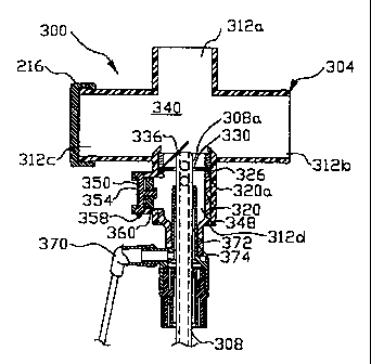
Turning now to FIG. 4A, there is shown another embodiment of an improved
respiratory suction catheter apparatus, generally indicated at 300, made in
accordance with
the principles of the present invention. The improved respiratory suction
catheter apparatus
300 includes a manifold 304 and a catheter 308. As with the previous
embodiment, the
manifold 304 includes a first port 312a, a second port 312b, a third port 312c
and a fourth
port 312d.
An adapter 320 is disposed in the fourth port 312d in such a manner as to make
the
manifold 304 and the catheter 308 a functionally integrated unit. The adapter
320 may be
adhesively attached to the manifold 304, or may be s:imply force-fit.
Unlike the embodiment discussed with FIGs. 3A through 3D, an annular ring is
not
disposed in the manifold 304 independent of the adapter 320. Rather, an
annular ring 326
extends inwardly from a distal end 320a of the adapter 320. The annular ring
326 defines an
aperture or opening 330 through which the catheter 308 can be extended. Thus,
the opening
330 is slightly larger than the exterior of the catheter 308.
Also extending inwardly from the adapter 320 is a flap 336. The flap 336 is
preferably hingedly attached to either the adapter directly or to the annular
ring 326. When
no suction is applied to the catheter 308, or when t;he distal end 308a of the
catheter is
disposed distally from the flap 336, the flap will generally extend distally
from the annular
ring 326 and provide virtually no resistance to advancement of the catheter
308.
As shown in FIG. 4B, as the distal end 308a of tkhe catheter 308 is withdrawn
through
the annular ring 326 while suction is applied, a vacuum is created which pulls
the flap 336
over the opening 330, thereby isolating the distal end 308a of the catheter
308 from the
ventilation circuit 340 and preventing the catheter froxn drawing air away
from a patient to
whom the manifold is attached. While the flap 336 coul!d be configured in the
manner shown
in FIGs. 3C and 3D, the present configuration does not riecessitate the use of
makeup air from
the ventilation circuit 340.
If the catheter 308 were simply left in the chatxiber 348 behind the flap
336/annular
ring 326 and lavage were injected into the chamber, a. substantial negative
pressure could
build within the chamber. Additionally, because no rellief is provided, it
would be difficult
12
CA 02343889 2001-03-13
WO 00/15284 PCT/US99/21225
to suction any mucus etc. from the chamber once the lavage source had been
sucked dry.
To overcome these problems with the prior art, the embodiment in FIGs. 4A
through
4C has a make-up air inlet, generally indicated at 350 which is formed in a
portion of the wall
defming the fourth port 312d of the manifold and the adapter 320. The make-up
air inlet 350
preferably includes a filter 354 which is selected to substantially prevent
cross-contamination
between the environment/clinicians and the patient. Disposed adjacent to the
filter material
is a flexible material 358 which forms a one-way valve 360.
As shown in FIG. 4C, the one-way valve 358 will generally be closed when the
catheter 308 is in an extended position, wherein the catheter extends through
the opening 330
in the annular ring 326. However, once the distal end 308a of the catheter 308
has been
withdrawn through the opening 330 in the annular ring 326 and the flap 336 has
been drawn
closed, a vacuum will quickly develop on the side of the flap 336 opposite the
respiration
circuit 340. The vacuum.causes the one-way valve 358 to open and allow a
supply of
makeup air to enter the chamber. The makeup air flowing past the flexible one-
way valve
member 358, helps to create turbulent airflow and facilitates removal of any
respiratory
secretions on the catheter 308. This is preferably accomplished at about the
same time the
user utilizes the lavage port 370 to inject lavage/cleaning solution through
the space 372
between the collar 374 and the catheter 308. It will be appreciated that the
one-way valve
358 could be configured to provide very little resistance to air inflow, or
could be configured
to require a substantial vacuum to be present before makeup air is allowed
into the area
proximal the flap 336.
Turning now to FIG. 5A, there is shown a fragmented, cross-sectional view of
an
altemative embodiment of an improved respiratory suction catheter apparatus,
generally
indicated at 400. The respiratory suction catheter apparatus includes a
manifold 404 and a
catheter 408 which is moveable through the manifold, to suction secretions
from a patient's
lungs. As with the previously discussed embodimentsõ the manifold includes a
first port 412a
for attachment to an endotracheal tube or other artificial airway, a second
port 412b for
attachment to the ventilator tubes of a mechanical ventilator, a third port
412c which is
covered with a cap 416, and a fourth port 412d which receives the connector or
adaptor 420.
Disposed at the distal end 420a of the adaptor 420 is a valve 424 in a
configuration
which is commonly referred to as a duckbill valve. The valve 424 is formed by
a piece of
13
CA 02343889 2001-03-13
WO 00/15284 PCTIUS99/21225 resilient material which opens as the catheter 408
is advanced therethrough, and closes when
the catheter is withdrawn. The valve 424 is attached to the adaptor 420 by a
flexible base
428.
Also disposed in the adaptor 420 is an air inlet 432 which includes a filter
material
436 and a resilient member 440 configured to for.m a one-way valve 444 similar
to that
discussed in the previous embodiment. While duckbill valves have been used in
endotracheal
catheter systems in the past, the valve 424 shown iin FIGs 5A through 5C is
substantially
advanced in several respects. First, as shown in FIGs. 5A and 5C, the interior
of the valve
424 has helical grooves 450 formed therein. The hel:ical grooves 450 help to
create turbulent
airflow around the distal end 408a of the catheter 408. Additionally, the
flexible base 428
is configured to allow the valve 420 to be drawn toward the collar 460 to
thereby reduce
space and improve removal of secretions from the exterior of the catheter 408.
Turning now specifically to FIG. 513, there is shown a cross-sectional view
similar
to that shown in FIG. 5A, but with the distal end 408a of the catheter 408 in
a retracted
position. Once the distal end 408a of the catheter 408 is withdrawn proximally
from the
valve 424, the suction through the catheter works against the flexible base
428 of the valve
and draws the valve toward the collar 460. A pair of air inlets 470 are
disposed at the base
428 of the valve 424 and allow air into the valve.
Applying suction to the valve 424 and through the air inlets 470 as shown in
FIG. 5B
creates a vacuum between the adaptor 420 and the flexible base 428, thereby
causing the one-
way valve 444 to open and allow air into the air inlets 470 at the top of the
collar 460. This
air mixes with the water injected through the lavage port 480 and turbulently
travels along
the distal end 408a of the catheter 408. The turbulent motion of the air/water
mixture is
enhanced by the helical grooves 450.
Once suction through the catheter 408 is sitopped, there is no longer a
negative
pressure to keep the flapper valve 444 open, or to maintain the valve 444
adjacent to the
distal end of the collar. Thus, the valve 424 will return to the position
shown in FIG. 5A,
except that it will be closed as the catheter 408 remains substantially in the
collar until the
next use.
Turning now to FIG. 6A, there is shown a cross-sectional view of yet another
alternative embodiment of an improved endotracheal catheter made in accordance
with the
14
CA 02343889 2001-03-13
WO 00/15284 PCT/US99/21225
principles of the present invention. The endotracheid catheter 500 includes a
manifold 504
and a catheter 508. The manifold 504 has a first port 512a for at tachment to
the hub of an
artificial airway of a patient, and a second port 512b for attachment to the
ventilator tubes
(not shown) of a mechanical ventilator so as to define a ventilation circuit
516.
The manifold.also includes a third port 512c which is configured to receive
the
catheter 508. Disposed in the third port 512c are a pair of floating flexible
disks or
membranes 520 and 524. Each of the disks defneis an aperture or opening 528
and 532,
respectively, through which the catheter 508 may be slid. An end view of the
disks 520 and
524 with the catheter being slid therethrough is shown in FIG. 6D.
When the catheter 508 is withdrawn through the openings 528 and 532 in the
disks,
a vacuum is created proximally of the disks 520 and 524. The vacuum draws both
of the
disks toward the end of the catheter 508, as shown iri FIG. 6B. This
substantially seals the
two disks together in an arrangement without overlapping openings as shown in
FIGs. 6B and
6C. This configuration minimizes or eliminates (depending on the seal) air
flow out of the
respiration circuit as lavage solution is injected through the lavage port 540
and the distal end
508a of the catheter 508 is cleaned.
Because the lavage port 540 is disposed behind the disks 520 and 524 which
provide
a significant impediment to lavage flowing to the lungs if needed, a second
lavage port 550
can be added distally from the disks. The second lavage port 550 would
typically not be used
for cleaning of the catheter 508.
Turning now to FIG. 7A there is shown a cross-sectional view of still another
embodiment of an improved endotracheal catheter rnade in accordance with the
principles
of the present invention. Most portions of the endotracheal catheter shown in
FIG. 7A are
the same as those discussed with respect to FIGs.. 6A through 6D and are
numbered
accordingly. The one major difference between the e;mbodiments of FIGs. 6A
through 6D
and FIG. 7A is that the disks 520 and 524 of the pre'%rious embodiment are
replaced with a
resilient closing membrane 570 which is attached at one end 570a to the
manifold 504 and
at an opposing end 570b to an adapter 572 holding ithe catheter 508. The
adapter 572 or
manifold 504 can be rotated to twist the membrane 570 and thereby either
reduce or enlarge
the size of a hole 580 (FIG. 7B) formed by the material. By twisting the
resilient material
570 to close the hole 580, the drawing of air from the respiration circuit 516
can be reduced
CA 02343889 2001-03-13
WO 00/15284 PCTIUS99/21225
or even eliminated.
When suctioning of patient is desired, the resilient material 570 is rotated
to allow the
catheter to pass therethrough. Because swivels 574 are disposed on the first
and second ports
512a and 512b, the rotation of the resilient material to expand or contract
the hole
therethrough will provide virtually no discomfort to the patient, while
effectively controlling
the amount of air which is drawn from the respiration circuit 516 when the
distal end 508a
of the catheter 508 is being cleaned.
FIG. 7B shows an end view of the resilient membrane 570. By rotating the
resilient
membrane 570 in one direction, the hole 580 is enlarged. By rotating the
resilient material
in an opposing direction, the size of the hole 580 is reduced.
Turning now to FIGs. 8A and 8B, there is shown yet another endotracheal
catheter
embodying principles of the present invention. The respiratory suction
catheter apparatus
600 includes a manifold 604 and a catheter 608 which is moveable through the
manifold. As
with many of the embodiments discussed previously, the manifold 604 includes a
first port
612a for connection to the hub of an endotracheal tube, a second port 612b for
coiinection
(via ventilator tubes) to a mechanical ventilator, and a third port 612c and
cap 616 which can
be used for blow-by.
The fourth port 612d is different from those discussed previously because it
has a
shroud 620 placed therein. The shroud 620 is attached to a plunger 624 so as
to allow the
user to move the shroud between a first position adjacent the sidewall of the
fourth port 612d
(FIG. 8A) and a second position (FIG. 8B) wherein the shroud is disposed
approximately at
the center of the port 612d.
During use of the respiratory suction catheter apparatus 600, the shroud 620
will
typically be moved into the first position so that it does not interfere with
advancement of the
catheter 608 through the manifold 604. Once suctioning has been completed, the
catheter
608 is withdrawn into the collar 634. The plunger 624 is then pressed so as to
move the
shroud 620 over the distal end 634a of the collar 634 to cover the distal end
608a of the
catheter 608. Typically, the catheter 608 will then be advanced toward the
distal end 620a
of the shroud 620. Lavage/cleaning solution will then ibe applied through the
lavage port 640
while suction is applied.
If desired, a small gap can be formed between the shroud 620 and the collar
634 to
16
CA 02343889 2001-03-13
WO 00/15284 PCT/US99/21225
ensure turbulent airflow into the distal end 608a of the catheter 608.
Likewise, grooves or
some other pattern may be formed in the shroud to encourage turbulent airflow.
Additionally, a valve member may be included to allow for make-up air in a
similar manner
as discussed with several of the embodiments above.
Thus there is disclosed an improved respiratory suction apparatus. Those
skilled in
the art will appreciate numerous modifications which can be made without
departing from
the scope and spirit of the present invention. The appended claims are
intended to cover such
modifications.
17