Language selection

Search

Patent 2344062 Summary

Third-party information liability

Some of the information on this Web page has been provided by external sources. The Government of Canada is not responsible for the accuracy, reliability or currency of the information supplied by external sources. Users wishing to rely upon this information should consult directly with the source of the information. Content provided by external sources is not subject to official languages, privacy and accessibility requirements.

Claims and Abstract availability

Any discrepancies in the text and image of the Claims and Abstract are due to differing posting times. Text of the Claims and Abstract are posted:

  • At the time the application is open to public inspection;
  • At the time of issue of the patent (grant).
(12) Patent Application: (11) CA 2344062
(54) English Title: HALLUX VALGUS BRACE
(54) French Title: ATTELLE POUR HALLUX VALGUS
Status: Deemed Abandoned and Beyond the Period of Reinstatement - Pending Response to Notice of Disregarded Communication
Bibliographic Data
(51) International Patent Classification (IPC):
  • A61F 5/01 (2006.01)
(72) Inventors :
  • SMITS, JAN
(73) Owners :
  • CAMP SCANDINAVIA AB
(71) Applicants :
  • CAMP SCANDINAVIA AB (Sweden)
(74) Agent: SMART & BIGGAR LP
(74) Associate agent:
(45) Issued:
(86) PCT Filing Date: 1999-09-15
(87) Open to Public Inspection: 2000-03-23
Availability of licence: N/A
Dedicated to the Public: N/A
(25) Language of filing: English

Patent Cooperation Treaty (PCT): Yes
(86) PCT Filing Number: PCT/SE1999/001608
(87) International Publication Number: WO 2000015163
(85) National Entry: 2001-03-14

(30) Application Priority Data:
Application No. Country/Territory Date
9803110-7 (Sweden) 1998-09-15

Abstracts

English Abstract


The invention relates to a hallux valgus brace, i.e. a brace designed for
treatment of non-rigid hallux valgus. The brace comprises a three point lever
means for correcting the position of the big toe. According to the invention
the complete brace (1) is designed to be located distally of the metatarsal
joint. Preferably, the brace comprises a proximal pad (2) pressing on the
first phalanx of the big toe, a distal pad (3) pressing on the distal end of
the first phalanx of the big toe, and a lever arm (4) pressing on the ball of
the foot. The brace can be used during walking and other activities.


French Abstract

L'invention se rapporte à une attelle pour hallux valgus, c'est-à-dire une attelle conçue pour le traitement d'hallux valgus non rigide. Cette attelle comporte un organe à effet de levier en trois points qui permet de corriger la position du gros orteil. Conformément à cette invention, la totalité de l'attelle (1) est conçue pour être placée à distance de l'articulation métatarsienne. De préférence, cette attelle comporte un coussinet proximal (2) qui fait pression sur la première phalange du gros orteil, un coussinet distal (3) qui fait pression sur la partie distale de la première phalange du gros orteil et un bras de levier (4) qui fait pression sur l'extrémité antérieure de la plante du pied. Cette attelle peut être portée pour la marche et d'autres activités.

Claims

Note: Claims are shown in the official language in which they were submitted.

CLAIMS
1. A hallux valgus brace comprising a three point lever means for correcting
the position of the big toe, characterised in that the brace (1) including the
three
point lever means is designed to be located distally of the metatarsal joint,
wherein
the three points of the lever means are one point (A) on the medial side of
the first
phalanx of the big toe, one point (B) on the lateral side of the distal end of
the big
toe, and one point (C) on the ball of the foot.
2. A brace according; to claim 1, characterised in that the brace (1)
comprises a proximal pad (2) pressing (A) on the first phalanx of the big toe,
a
distal pad (3) pressing (B) on the distal end of the big toe, and a lever arm
(4)
pressing (C) on the ball of the foot.
3. A brace according; to claim 2, characterised in that the distal pad (3) is
adapted to press (B) on the distal end of the first phalanx of the big toe.
4. A brace according to claim 2 or 3, characterised in that the distal pad (3)
is disposed on an adjustable arm (5).
5. A brace according to claim 4, characterised in that the adjustable arm (5)
is secured to a sleeve (6) which is slidable and may be fixed with glue.
6. A brace according to any one of the preceding claims, characterised in
that the brace is manufactured from steel wire and steel pads.
7. A brace according to any one of claims 2-6, characterised in that the
lever arm (4) is provided with a silicone tube (7).
8. A brace according to any one of the preceding claims, characterised in
that a strap (8) is provided for fitting around the third toe.
9. A brace according to claim 7, characterised in that the strap (8) is made
of rubber or plastic or a hook and loop connection.
10. A brace according to any one of the preceding claims, characterised in
that the distal pad (3) carries a strap (9) to be located around the big toe.

Description

Note: Descriptions are shown in the official language in which they were submitted.


WO 00/15163 PCT/SE99/01608
HALLUX VALGUS BRACE
Field of the invention
The present invention relates to a hallux valgus brace, i.e. a brace designed
for treatment of non-rigid hallux valgus. The complete brace is positioned in
front
of the metatarsal joint and can be used during walking and other activities.
State of the art
Hallux valgus is a painful malposition of the big toe, where the big toe turns
towards the other toes and a bunion is formed on the protruding joint, i.e.
the first
metatarsal joint. This deformity has been treated in the past mainly by means
of
night splints or braces. The brace is mainly used during sleeping or resting.
The
brace uses three pressure points, two of which are located at the metatarsus.
Thus,
the prior art brace requires support proximal of the metatarsal joint. The
brace
1 S bridges the metatarsal joint resulting in that the brace is not suitable
for walking
because the bending of the joint together with the brace is not comfortable or
even
impossible.
The present invention solves this problem by positioning the complete brace
distally of the metatarsal jjaint. Thus, all components of the brace are
located
distally of the metatarsal jioint and the brace is not affected by the bending
of the
joint during walking and other activities. In this way, the brace of the
invention
may be used for conservative dynamic treatment of non-rigid hallux valgus. In.
other words, the patient nnay wear the brace practically at all times
resulting in an
efficient treatment.
Summary of the invention
Thus, the present invention provides a hallux valgus brace comprising a
three point lever means for correcting the position of the big toe.
According to the invention the complete brace is designed to be located
distally of the metatarsal joint. Preferably, the brace comprises a proximal
pad
pressing on the medial side on the first phalanx of the big toe, a distal pad
pressing
on the distal end of the first phalanx, and a lever arm pressing on the ball
of the
foot.
The invention is defined in claim 1 while preferred embodiments are set
forth in the dependent claims.
Brief description of the draw_ inns
The invention will be described in detail below with reference to the accom-
panying drawings in which:
CA 02344062 2001-03-14

-------.-_ .
Try ~~.;~~~,. J"_~at~nt C~;i~e ''C-T/SE 9 9 /~' l ~ C ~
II PCT International ,o~ppiicatien
2
2 7 -03- 20~
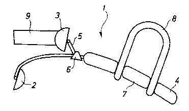
figure 1 is a bottom view of the brace on the foot of a patient;
figure 2 is a detail view of one component of the brace carrying the distal
pad:
figure 3 is a detail view of the main part of~ the brace: and
figure 4 is a bottom view of the complete brace according to the invention.
Detailed description of~refe:rred embodiments
The hallux valgus brace according to the invention is now described with
reference to the drawings. In figure l, the brace is shown as worn by a
patient on a
foot. The skeletal bones of th.e foot are shown for reference. In figure 4,
the
complete brace 1 is shown by itself. The brace is located in the space which
exists
under the normally slightly bent toes. At the medial side the brace carries a
proximal pad 2 pressing on the first phalanx of the big toe. A distal pad 3 is
carried
by an adjustable arm 5 and presses on the distal end of the big toe,
preferably on
1 ~ the distal end of the first phalanx.
The pads 2 and 3 are connected to the frame of the brace by means of
hinges, so that the pads can turn and adapt themselves to the curvature of the
contact area between the pad: and the toe. Thus, the pads 2 and 3 are self
adjusting
for better fit and comfort.
The lateral part of the brace comprises a Icver arm 4 pressing backwards and
acting as a counterforce on th.e ball of the foot. The lever arm 4 also
carries a strap
8, best shown in figures 3 and 4. Another toe is inserted through the strap 8
serving
to prevent the lever arm 4 from sliding down. This is preferably the third toe
since
this toe is a little longer and stronger but also e.g. the fourth toe could be
used.
The adjustable arm 5 is connected to the main part of the brace by means of
a sleeve 6. The sleeve 6 may be slid to a correct position in order to
accommodate
various sizes of big toes. Whc:n the sleeve 6 is positioned correctly it may
be fixed
with glue.
The brace is manufactured from stainless steel spring-wire, thickness e.g.
1,75 mm. The pads 2 and 3 are cup shaped pads, made of steel sheet, thickness
e.g.
0,6 mm or injection moulded plastic. The adjustable sleeve 6 is also
preferably
made of stainless steel.
For best comfort the lever arm 4 may carry a silicone tube 7. The strap 8 is
suitably made of rubber or plastic, but may also be made of leather, cotton or
a
hook and loop connection (Vc;lcro~ fastening).
The distal pad 3 may carry another strap or fastening means 9 to be
located around the big toe and preventing the pad from sliding off. This strap
9
suitably comprises a hook anti loop connection for easy fastening and
adjustment.
The brace according to the invention can be used in a dynamic way. Since
A~,r'~i.!~EU SHt"ET
CA 02344062 2001-03-14

WO 00/15163 PCT/SE99/01608
3
all correcting and stiff parts are located distally of the metatarsal joint
the brace
does not interfere with normal walking. The brace has a lever means with a
clear
three point working print;iple. A force A on the medial side moves the first
phalanx
laterally while a force B on the lateral side moves the distal end of the
first phalanx
and the toe medially. The. reaction force C is applied against the soft tissue
of the
ball of the foot.
For the brace of the invention to be efficient the first metatarsal joint
needs
to be flexible enough to be repositioned and flexed in a horizontal plane. The
patient should wear a shoe or slipper providing sufficient room for the medial
movement of the toe.
The brace according to the invention is intended to be delivered as an "of
the shelf' item and requires adjustments before it can be worn by a patient.
Thus,
the wire parts of the brace; are bent for a proper fit. The sleeve 6 is
positioned
correctly and preferably glued to secure it to the wire. It is suitable that
this work is
performed by an orthotist/bandagist or possibly a podiatrist, even if patients
even-
tually may learn to fit the braces themselves.
Thus, the present invention provides several advantages over the prior art.
The brace allows for a dynamic treatment since the brace may be used at all
times
during walking, resting etc. and in normal shoes. The brace is adaptable for
various
foot sizes by means of some simple adjustments only. The brace is very light-
weight and very comfortable.
A person skilled in the art will appreciate that the brace of the invention
may
be modified without departing from the scope of the invention. Thus, the
embodi-
ment shown is just given as an example of shapes and materials that rnay be
used.
The scope of the invention is only limited by the claims below.
CA 02344062 2001-03-14

Representative Drawing
A single figure which represents the drawing illustrating the invention.
Administrative Status

2024-08-01:As part of the Next Generation Patents (NGP) transition, the Canadian Patents Database (CPD) now contains a more detailed Event History, which replicates the Event Log of our new back-office solution.

Please note that "Inactive:" events refers to events no longer in use in our new back-office solution.

For a clearer understanding of the status of the application/patent presented on this page, the site Disclaimer , as well as the definitions for Patent , Event History , Maintenance Fee  and Payment History  should be consulted.

Event History

Description Date
Application Not Reinstated by Deadline 2005-09-15
Time Limit for Reversal Expired 2005-09-15
Inactive: IPRP received 2004-11-04
Inactive: Abandon-RFE+Late fee unpaid-Correspondence sent 2004-09-15
Deemed Abandoned - Failure to Respond to Maintenance Fee Notice 2004-09-15
Letter Sent 2001-10-24
Inactive: Single transfer 2001-09-19
Inactive: Cover page published 2001-06-11
Inactive: First IPC assigned 2001-06-03
Inactive: Courtesy letter - Evidence 2001-05-29
Inactive: Notice - National entry - No RFE 2001-05-24
Application Received - PCT 2001-05-15
Application Published (Open to Public Inspection) 2000-03-23

Abandonment History

Abandonment Date Reason Reinstatement Date
2004-09-15

Maintenance Fee

The last payment was received on 2003-08-19

Note : If the full payment has not been received on or before the date indicated, a further fee may be required which may be one of the following

  • the reinstatement fee;
  • the late payment fee; or
  • additional fee to reverse deemed expiry.

Please refer to the CIPO Patent Fees web page to see all current fee amounts.

Fee History

Fee Type Anniversary Year Due Date Paid Date
Basic national fee - standard 2001-03-14
MF (application, 2nd anniv.) - standard 02 2001-09-17 2001-09-07
Registration of a document 2001-09-19
MF (application, 3rd anniv.) - standard 03 2002-09-16 2002-08-23
MF (application, 4th anniv.) - standard 04 2003-09-15 2003-08-19
Owners on Record

Note: Records showing the ownership history in alphabetical order.

Current Owners on Record
CAMP SCANDINAVIA AB
Past Owners on Record
JAN SMITS
Past Owners that do not appear in the "Owners on Record" listing will appear in other documentation within the application.
Documents

To view selected files, please enter reCAPTCHA code :


To view images, click a link in the Document Description column. To download the documents, select one or more checkboxes in the first column and then click the "Download Selected in PDF format (Zip Archive)" or the "Download Selected as Single PDF" button.

List of published and non-published patent-specific documents on the CPD .

If you have any difficulty accessing content, you can call the Client Service Centre at 1-866-997-1936 or send them an e-mail at CIPO Client Service Centre.


Document
Description 
Date
(yyyy-mm-dd) 
Number of pages   Size of Image (KB) 
Representative drawing 2001-06-11 1 5
Cover Page 2001-06-11 1 27
Abstract 2001-03-14 1 53
Description 2001-03-14 3 175
Claims 2001-03-14 1 48
Drawings 2001-03-14 2 31
Claims 2001-03-15 1 56
Description 2001-03-15 3 186
Reminder of maintenance fee due 2001-05-22 1 111
Notice of National Entry 2001-05-24 1 193
Courtesy - Certificate of registration (related document(s)) 2001-10-24 1 113
Reminder - Request for Examination 2004-05-18 1 116
Courtesy - Abandonment Letter (Request for Examination) 2004-11-24 1 167
Courtesy - Abandonment Letter (Maintenance Fee) 2004-11-10 1 176
Correspondence 2001-05-24 1 23
PCT 2001-03-14 10 424
PCT 2001-03-15 5 294