Language selection

Search

Patent 2344237 Summary

Third-party information liability

Some of the information on this Web page has been provided by external sources. The Government of Canada is not responsible for the accuracy, reliability or currency of the information supplied by external sources. Users wishing to rely upon this information should consult directly with the source of the information. Content provided by external sources is not subject to official languages, privacy and accessibility requirements.

Claims and Abstract availability

Any discrepancies in the text and image of the Claims and Abstract are due to differing posting times. Text of the Claims and Abstract are posted:

  • At the time the application is open to public inspection;
  • At the time of issue of the patent (grant).
(12) Patent: (11) CA 2344237
(54) English Title: MOULD COMPRISING OUTER MOULD PARTS AND MOULDING MATERIAL CORES INSERTED INTO SAME
(54) French Title: MOULE COMPRENANT LES PARTIES EXTERNES DU MOULE ET LES MATERIAUX DES NOYAUX DE MOULAGE INSERES DANS CE MEME MOULE
Status: Expired and beyond the Period of Reversal
Bibliographic Data
(51) International Patent Classification (IPC):
  • B29C 39/26 (2006.01)
  • B22C 09/06 (2006.01)
  • B22C 09/10 (2006.01)
  • B22D 23/00 (2006.01)
  • B29C 33/00 (2006.01)
  • B29C 39/22 (2006.01)
(72) Inventors :
  • WILLFORT, PETER (Austria)
  • BOHN, HORST (Austria)
(73) Owners :
  • VAW MANDL & BERGER GMBH
(71) Applicants :
  • VAW MANDL & BERGER GMBH (Austria)
(74) Agent: SMART & BIGGAR LP
(74) Associate agent:
(45) Issued: 2005-02-15
(22) Filed Date: 2001-04-18
(41) Open to Public Inspection: 2001-10-19
Examination requested: 2001-04-18
Availability of licence: N/A
Dedicated to the Public: N/A
(25) Language of filing: English

Patent Cooperation Treaty (PCT): No

(30) Application Priority Data:
Application No. Country/Territory Date
100 19 310.2 (Germany) 2000-04-19

Abstracts

English Abstract


A mould comprising outer mould parts and inserted moulding
material cores which, together, form a mould cavity, wherein
inner cores consisting of moulding material are arranged in
several layers one above the other and are clamped in between
the outer mould parts and a final covering core consisting of
mould material, with a continuous flow of force taking place
therebetween and wherein the mould cavity is formed by
surfaces of the outer mould and by surfaces of the inner cores
and of the covering core.


Claims

Note: Claims are shown in the official language in which they were submitted.

-7-
CLAIMS:
1. A mould comprising metal outer moulded parts, inserted inner cores made of
moulding material and a covering core made of moulding material,
wherein a mould cavity is formed by surfaces of the outer mould parts (12, 23,
14) and by surfaces of the inner cores (15) and the covering core (16),
wherein the inner cores (15) are stacked in several layers one above the other
and are clamped in between the outer mould parts (12, 13, 14) and the covering
core (16), with a continuous clamping force taking place between the covering
core, the inner cores and the outer mould parts,
wherein the outer mould parts comprise a base plate (12) and several side
parts
which are mechanically connected to and moveable relative to said base plate
for enabling said side parts to be moved away from one another enabling
stacking of said inner cores and moving said side parts back together after
the
stacking of the inner cores, and
wherein the mould (11) is suspended so as to be rotatable about a horizontal
axis (16).
2. A mould according to claim 1, characterized in that the side parts (13, 14)
comprise two longitudinal side parts which, relative to the base plate (12),
can
be displaced outwardly away from the mould cavity in opposite directions.
3. A mould according to claim 1 or claim 2, characterized in that the side
parts
comprise at least one end side part which, relative to the base plate (12),
can be
pivoted away outwardly from the mould cavity.
4. A mould according to any one of claims 1 to 3, characterized in that at the
base
plate or at least at two side parts (13, 14), there are arranged displaceable
bolts
(21, 22) for holding the covering core (16).

-8-
5. A mould according to any one of claims 1 to 3, characterized in that at the
base
plate or at least at two side parts (13, 14), there are arranged pivotable
claws for
holding the covering core (16).
6. A mould according to any one of claims 1 to 5, characterized in that at the
inner
faces of the side parts (13, 14), there are provided mould projections (17,
18)
which hold individual cores (15) additionally relative to the base plate (12).
7. A mould according to any one of claims 1 to 6, characterized in that in the
base
plate (12), there are arranged ejectors (23, 24).
8. A mould according to any one of claims 1 to 7, characterized in that in the
covering core (16), there is provided at least one ingate aperture (33) and at
least one gas exit aperture (34).
9. Making use of a mould according to any one of claims 1 to 8, characterized
in
that the mould (11), after having been stacked on the base plate (12), is
rotated
by 180° around the horizontal axis (26), that a casting container (29)
containing
melt (32) for one casting operation is positioned from below in such a way
that
its aperture sealingly rests against the covering core (16), that the mould
(11)
together with the contacting casting container (29) is again rotated
by180°
around said horizontal axis (26), with the melt reaching the mould through an
ingate (33) in the covering core (16), and that then the casting container
(29) is
removed upwardly from the mould (11).
10. Using a mould according to claim 9, characterized in that the mould (11)
is
rotated around a horizontal axis (26) which extends parallel to the
longitudinal
extension of the mould cavity.

Description

Note: Descriptions are shown in the official language in which they were submitted.


CA 02344237 2001-04-18
Mould comprising outer mould parts and moulding
material cores inserted into same
Description
The invention relates to a mould comprising outer mould parts
and inserted mould material cores which, together, form a
mould cavity. The outer mould parts can be parts of a
permanent mould and/or moulding material parts/outer cores.
For producing complicated mouldings, for example of cylinder
heads, it is necessary to insert moulding material cores into
the outer mould parts. It is already known to use outer
moulding material cores as well, so that substantial parts of
the outer casting faces are not formed by a metallic mould
wall, but by outer cores consisting of moulding material. This
method is particularly suitable for casting aluminium and
magnesium alloys.
It is the object of the present invention to provide a mould
of said type which can be used for complicated castings and
which, in particular, is suitable for rotary casting.
The objective is achieved in that the inner cores consisting
of moulding material are stacked in layers one above the other
and are clamped in between the outer mould parts and the final
covering core consisting of moulding material, with a

CA 02344237 2001-04-18
-2-
continuous flow of force taking place between the covering
core, the inner cores, and the outer mould parts, wherein the
mould cavity is formed by surfaces of the outer mould parts
and by surfaces of the inner cores and of the covering core.
In accordance with the invention, there are not provided any
additional means for fixing the moulding material cores in the
outer mould cores and for fixing the moulding material cores
between each other. The multi-layer structure permits the
production of complicated shapes. By using the final covering
core consisting of moulding material, it is possible to
directly connect a casting container (contact casting). The
covering core preferably comprises at least one ingate
aperture and at least one gas exit aperture.
According to a fuxther embodiment it is proposed that the
parts of the mould comprise a base plate and several side
parts which are movable relative to said base plate. The side
parts can comprise especially two longitudinal side parts
which, relative to the base plate, can be displaced outwardly
away from the mould cavity in opposite directions and/or at
least one end side part which, relative to the base plate, can
be pivoted away outwardly from the mould cavity. This measure
permits a problem-free structure of the inner cores consisting
of several, stacked-layers. The inner faces of the side parts
can be provided with projections which hold individual inner
cores additionally relative to the base plate. For securing
the covering core, displaceable bolts or pivotable claws can
be arranged at the base plate or at least at two side parts,
which bolts or claws hold the package of moulding material
cores within a mould in such a way that, even when the mould
rotates, displacements between the inner cores cannot occur.

CA 02344237 2001-04-18
-3-
An inventive mould is used in a particularly advantageous way
if the mould is first stacked on the base plate and is then
rotated by 1~0- around a horizontal axis, so that the covering
core comprising an ingate aperture comes to rest downwards.
Subsequently, a casting container filled with melt for one
casting operation is coupled to the covering core. When the
assembly is again rotated by 180° around the horizontal axis,
the melt flows through the ingate aperture in the covering
core into the mould cavity. Thereafter, the melt container is
removed and the casting solidifies whereupon the mould is
removed. The mould is preferably rotated around an axis which
extends parallel to the longitudinal extension of its mould
cavity.
The base plate is provided in the form of a permanent mould
part consisting of metal. The outer.mould parts can also be
permanent mould parts mechanically connected to the base
plate, or they can be moulding material parts which, by
mechanical clamping means, are clamped together and clamped on
to the base plate from the sides and from above.
An embodiment of the. invention is illustrated in the drawings
and described below.
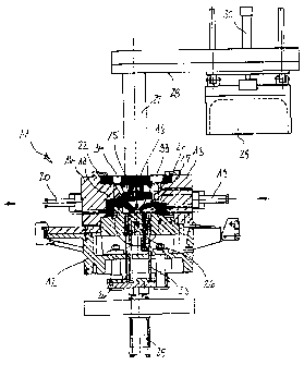
Figure 1 shows an inventive mould in a first position after
having been assembled.
Figure 2 shows an inventive mould in a second position before
the casting process starts.
Figures 1 and 2 will largely. be described jointly. An
inventive mould 11 comprises a multi-component base plate 12,

CA 02344237 2001-04-18
-4-
side parts 13, 14 each in the form of permanent mould parts, a
plurality of inner cores 15 stacked in several layers one
above the other on the base plate 12, and a covering core 16,
each consisting of moulding material. The plurality of inner
cores 15 are clamped in between the base plate 12 and the
covering core 16 with a continuous flow of force existing
therebetween. The side parts 13, 14 are provided with mould
projections 17, 18 which additionally hold individual inner
cores 15 against the base plate 12. By means of setting
cylinders 19, 20, the side parts 13, 14 can be displaced in
opposite directions relative to the base plate 12; they can be
removed from one another relative to the illustrated position.
Thereafter, the inner cores 15 can be stacked on the base
plate 12. Following this operation, the side parts 13, 14 can
be closed again, as indicated by the arrows pointing in
opposite directions, to enable~same, once again, to return
into the indicated position. Then the covering core 16 is
placed in position. On the side parts 13, 14, there are
arranged bolts 21, 22 which, to permit assembly can be slid
back relative to the side parts 13, 14, and after the covering
core 16 has been placed in position, they can be moved forward
into the illustrated position in which they hold the covering
core 16 relative to the inner cores 15 and the side parts 13,
14. The base plate-12 is shown to have ejectors 23, 24 which
are actuated by a setting cylinder 25 for the purpose of
removing the casting from the mould. The base plate 12 and
thus the entire mould 11 can be rotated around a horizontal
axis 27 extending perpendicularly relative to the drawing
plane. This applies in the same way to the column 27 on which
there is supported a pivot arm 28 carrying a casting container
29 which, by means of a setting cylinder 30, can be displaced
parallel to the column 27 on the pivot arm 28.

CA 02344237 2001-04-18
-5-
Figure 1 shows the finish-assembled mould 11 in its position
assumed directly after the stacking operation. The casting
container 29 is suspended upside down, has been removed by the
setting cylinder 30 from the mould 11 and has been pivoted by
the pivot arm 28 on the column 27
by 90° relative to the mould.
In Figure 2, the mould 11 together with the column 27 and the
casting container 29 has been rotated by 180° around the axis
26. The casting container 29 is still in the same position
relative to the mould 11 as shown in Figure 1, but it is now
open towards the top and is just being filled by a dispensing
ladle 31 with melt 32 for one casting operation.
After the casting container 29 has been filled, the pivot arm
28 is pivoted by 90° relative to the column 27, so that the
casting container 29 comes to rest underneath the mould 11 in
front of the column 27. The casting container 29 is then
lifted by the cylinder 30 towards the mould 11 until the
casting container 29 rests sealingly against the covering core
16. In the position now assumed, the mould 11 with the coupled
casting container ,,29 is again rotated by 180° around the axis
26. The melt 32 weighed to fill the mould cavity flows through
the ingate 33 into the mould cavity, with gas being able to
escape from the gas exit 34 provided in the casting container
29. After completion of the rotating operation and thus of the
casting operation in which, once again, the mould 11 assumes
the position as shown in Figure 1, the casting container 29 is
lifted by the setting cylinder 30 from the mould 11 and
rotated by the pivot arm 28 back into the position as shown in
Figure 1. After the metal has solidified, the casting can be
removed from the mould by withdrawing the side parts 13, 14
and actuating the ejectors 23, 24.

CA 02344237 2001-04-18
'6'
The side parts 13, 14 can consist of moulding material, in
which case the bolts 21, 22 can be replaced by holding-down
devices connected to the base plate.

Representative Drawing
A single figure which represents the drawing illustrating the invention.
Administrative Status

2024-08-01:As part of the Next Generation Patents (NGP) transition, the Canadian Patents Database (CPD) now contains a more detailed Event History, which replicates the Event Log of our new back-office solution.

Please note that "Inactive:" events refers to events no longer in use in our new back-office solution.

For a clearer understanding of the status of the application/patent presented on this page, the site Disclaimer , as well as the definitions for Patent , Event History , Maintenance Fee  and Payment History  should be consulted.

Event History

Description Date
Time Limit for Reversal Expired 2009-04-20
Letter Sent 2008-04-18
Inactive: IPC from MCD 2006-03-12
Grant by Issuance 2005-02-15
Inactive: Cover page published 2005-02-14
Pre-grant 2004-12-02
Inactive: Final fee received 2004-12-02
Notice of Allowance is Issued 2004-07-21
Letter Sent 2004-07-21
Notice of Allowance is Issued 2004-07-21
Inactive: Approved for allowance (AFA) 2004-07-07
Amendment Received - Voluntary Amendment 2004-04-20
Inactive: S.30(2) Rules - Examiner requisition 2003-11-20
Application Published (Open to Public Inspection) 2001-10-19
Inactive: Cover page published 2001-10-18
Letter Sent 2001-08-15
Inactive: Single transfer 2001-07-06
Inactive: First IPC assigned 2001-07-04
Inactive: IPC assigned 2001-07-04
Inactive: Filing certificate - RFE (English) 2001-05-23
Inactive: Courtesy letter - Evidence 2001-05-22
Inactive: Filing certificate - RFE (English) 2001-05-17
Filing Requirements Determined Compliant 2001-05-17
Application Received - Regular National 2001-05-17
Request for Examination Requirements Determined Compliant 2001-04-18
All Requirements for Examination Determined Compliant 2001-04-18

Abandonment History

There is no abandonment history.

Maintenance Fee

The last payment was received on 2004-03-23

Note : If the full payment has not been received on or before the date indicated, a further fee may be required which may be one of the following

  • the reinstatement fee;
  • the late payment fee; or
  • additional fee to reverse deemed expiry.

Patent fees are adjusted on the 1st of January every year. The amounts above are the current amounts if received by December 31 of the current year.
Please refer to the CIPO Patent Fees web page to see all current fee amounts.

Fee History

Fee Type Anniversary Year Due Date Paid Date
Application fee - standard 2001-04-18
Request for examination - standard 2001-04-18
Registration of a document 2001-07-06
MF (application, 2nd anniv.) - standard 02 2003-04-18 2003-03-12
MF (application, 3rd anniv.) - standard 03 2004-04-19 2004-03-23
Final fee - standard 2004-12-02
MF (patent, 4th anniv.) - standard 2005-04-18 2005-03-22
MF (patent, 5th anniv.) - standard 2006-04-18 2006-03-24
MF (patent, 6th anniv.) - standard 2007-04-18 2007-03-26
Owners on Record

Note: Records showing the ownership history in alphabetical order.

Current Owners on Record
VAW MANDL & BERGER GMBH
Past Owners on Record
HORST BOHN
PETER WILLFORT
Past Owners that do not appear in the "Owners on Record" listing will appear in other documentation within the application.
Documents

To view selected files, please enter reCAPTCHA code :


To view images, click a link in the Document Description column. To download the documents, select one or more checkboxes in the first column and then click the "Download Selected in PDF format (Zip Archive)" or the "Download Selected as Single PDF" button.

List of published and non-published patent-specific documents on the CPD .

If you have any difficulty accessing content, you can call the Client Service Centre at 1-866-997-1936 or send them an e-mail at CIPO Client Service Centre.


Document
Description 
Date
(yyyy-mm-dd) 
Number of pages   Size of Image (KB) 
Representative drawing 2001-07-18 1 11
Claims 2001-04-17 5 90
Description 2001-04-17 6 218
Abstract 2001-04-17 1 17
Drawings 2001-04-17 2 46
Claims 2004-04-19 2 73
Representative drawing 2005-01-20 1 13
Filing Certificate (English) 2001-05-22 1 164
Courtesy - Certificate of registration (related document(s)) 2001-08-14 1 136
Reminder of maintenance fee due 2002-12-18 1 106
Commissioner's Notice - Application Found Allowable 2004-07-20 1 162
Maintenance Fee Notice 2008-06-01 1 171
Correspondence 2001-05-16 1 25
Fees 2003-03-11 1 33
Fees 2004-03-22 1 34
Correspondence 2004-12-01 1 25
Fees 2005-03-21 1 30