Language selection

Search

Patent 2344321 Summary

Third-party information liability

Some of the information on this Web page has been provided by external sources. The Government of Canada is not responsible for the accuracy, reliability or currency of the information supplied by external sources. Users wishing to rely upon this information should consult directly with the source of the information. Content provided by external sources is not subject to official languages, privacy and accessibility requirements.

Claims and Abstract availability

Any discrepancies in the text and image of the Claims and Abstract are due to differing posting times. Text of the Claims and Abstract are posted:

  • At the time the application is open to public inspection;
  • At the time of issue of the patent (grant).
(12) Patent: (11) CA 2344321
(54) English Title: METHOD OF FABRICATING A BACKWATER VALVE
(54) French Title: METHODE DE FABRICATION D'UN CLAPET ANTI-RETOUR
Status: Term Expired - Post Grant Beyond Limit
Bibliographic Data
Abstracts

English Abstract

A method of fabricating a backwater valve. A first step involves providing a fitting having at least two flow openings with an inner diameter. A second step involves providing an annular body having a central passage and a valve member movable between a closed position blocking the central passage and an open position. The annular body has an outer diameter adapted for close fitting insertion within the inner diameter of a selected one of the at least two flow openings. A third step involves inserting the annular body into the selected one of the at least two flow openings and securing the annular body in place.


French Abstract

L'invention concerne une méthode de fabrication d'un clapet anti-retour. La première étape consiste à prévoir un raccord ayant au moins deux orifices d'écoulement avec un diamètre intérieur. La deuxième étape consiste à prévoir un corps annulaire ayant un passage central et un élément de soupape amovible entre une position fermée bloquant le passage central et une position centrale. Le corps annulaire a un diamètre extérieur adapté à une insertion ajustée dans le diamètre intérieur d'une parmi au moins deux orifices d'écoulement. La troisième étape consiste à insérer le corps annulaire dans un des orifices d'écoulement et à maintenir le corps annulaire en place.

Claims

Note: Claims are shown in the official language in which they were submitted.

7
THE EMBODIMENTS OF THE INVENTION IN WHICH AN EXCLUSIVE
PROPERTY OR PRIVILEGE IS CLAIMED ARE DEFINED AS FOLLOWS:
1. A method of fabricating a backwater valve, comprising the
steps of:
firstly, providing a fitting having at least two flow
openings with an inner diameter and a horizontal flow path
between the at least two flow openings;
secondly, providing an annular body having a central
passage and a flap valve member movable between a closed
position blocking the horizontal flow path and an open
position, the annular body having an outer diameter adapted
for close fitting insertion within the inner diameter of a
selected one of the at least two flow openings; and
thirdly, inserting the annular body into the selected one
of the at least two flow openings and securing the annular
body in place by securing the outer diameter of the annular
body to the inner diameter of the selected flow opening.
2. The method as defined in Claim 1, wherein the fitting is
oversized.
3. The method as defined in Claim 1, wherein the annular body
is secured in place with adhesive.
4. A backwater valve, comprising:
a fitting having at least two flow openings with an inner
diameter, the fitting having a horizontal flow path between
the at least two flow openings;
an annular body having a central passage and a flap valve
member movable between a closed position blocking the
horizontal flow path and an open position, the annular body
having an outer diameter adapted for close fitting insertion
within the inner diameter of a selected one of the at least
one horizontally oriented flow opening, the outer diameter of
the annular body being attached to the inner diameter of the

8
fitting; and
the annular body being inserted into the selected one of
the at least two flow openings and secured in place.

Description

Note: Descriptions are shown in the official language in which they were submitted.


CA 02344321 2001-04-18
1
TITLE OF THE INVENTION:
Method of Fabricating a Backwater Valve
FIELD OF THE INVENTION
The present invention relates to a method of fabricating
a backwater valve
BACKGROUND OF THE INVENTION
Backwater valves are made in several standard sizes.
Problems arise when an installation is encountered that
requires an "odd" size of backwater valve. In such cases a
backwater valve must be custom made to suit the application at
a cost of several hundred dollars.
SUMMARY OF THE INVENTION
What is required is a less expensive method of fabricating
a "odd" sizes of backwater valves.
According to one aspect of the present invention there is
provided a method of fabricating a backwater valve. A first
step involves providing a fitting having at least two flow
openings with an inner diameter. A second step involves
providing an annular body having a central passage and a valve
member movable between a closed position blocking the central
passage and an open position. The annular body has an outer
diameter adapted for close fitting insertion within the inner
diameter of a selected one of the at least two flow openings.
A third step involves inserting the annular body into the
selected one of the at least two flow openings and securing the
annular body in place.
The method, as described above, enables a 6 inch backwater
valve to be made out of an 8 inch fitting through the use of
an insert.
According to another aspect of the present invention there
is provided a backwater valve which includes a fitting having

CA 02344321 2001-04-18
2
at least two flow openings with an inner diameter. An annular
body is provided having a central passage and a valve member
movable between a closed position blocking the central passage
and an open position. The annular body has an outer diameter
adapted for close fittirig insertion within the inner diameter
of a selected one of the at least two flow openings. The
annular body is inserted.into the selected one of the at least
two flow openings and secured in place.
BRIEF DESCRIPTION OF THE DRAWINGS
These and other fea:ures of the invention will become more
apparent from the following description in which reference is
made to the appended drawings, the drawings are for the purpose
of illustration only and are not intended to in any way limit
the scope of the invention to the particular embodiment or
embodiments shown, wherein:
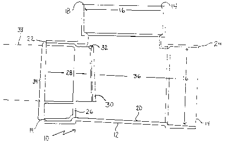
FIGURE 1 is a side elevation view of a tee fitting
provided in accordance with the teachings of a first step in
the preferred method.
FIGURE 2 is a top plan view of the tee fitting illustrated
in FIGURE 1.
FIGURE 3 is a side elevation view of an end insert
provided in accordance with the teachings of a second step in
the preferred method.
FIGURE 4 is a side elevation view, in section, of a
normally closed backwater valve fabricated in accordance with
a third step in the pref:erred method utilizing the end insert
illustrated in FIGURE 3..
FIGURE 5 is a sicie elevation view, in section, of a
normally open backwater valve fabricated in accordance with a
third step in the preferred method utilizing the end insert
illustrated in FIGURE 3.
FIGURE 6 is a side elevation view of a top insert provided
in accordance with the teachings of a second step in the
preferred method.
FIGURE 7 is a top plan view of the top insert illustrated

CA 02344321 2001-04-18
3
in FIGURE 6.
FIGURE 8 is a side elevation view, in section, of a
normally closed backwater valve fabricated in accordance with
a third step in the preferred method utilizing the top insert
illustrated in FIGURE 6.
FIGURE 9 is a top plan view of the backwater valve
illustrated in FIGURE 8.
DETAILED DESCRIPTION OF THE PREFERRED EMBODIMENT
The preferred method of fabricating a backwater valve 10
will now be described with reference to FIGURES 1 through 9.
Referring to FIGURES 1 and 2, a first step involves
providing an fitting 12 that has at least two flow openings 14
with an inner diameter 16. Generally, an oversized fitting is
used. What is meant by "oversized" is that it has flow openings
that have inner diameters that are larger than required. This
allows an insert to be inserted while still maintaining an
inner diameter which provides a flow channel of the desired
size. Referring to FIGURE 4, in the illustrated embodiment,
fitting 12 is a tee fitting that is adapted for use in a
substantially horizontal orientation with a top 18, a bottom
20, a first end 22 and a second end 24. In the illustrated
embodiment, flow openings 14 are positioned at first end 22,
second end 24 and at top 18 of fitting 12, however it will be
appreciated that other types of fittings 12 which may have
different arrangements of flow openings 14 can be used, so long
as fitting 12 has at least two flow openings 14.
Referring to FIGURE 3, a second step involves providing
an annular body 26 that has a central passage 28 and a valve
member 30 that is movable between a closed position blocking
central passage 28 and an open position. Valve member 30 is
secured to annular body 26 by a pivotal connection 32. Annular
body 26 has an outer diameter 34 adapted for close fitting
insertion within inner diameter 16 of one of flow openings 14.
Annular body 26 has an inner diameter which is adapted to
receive a conduit 33 in mating relation, which directs the flow
of fluid into annular body 26.

CA 02344321 2001-04-18
4
Referring to FIGURE 4 a third step involves inserting
annular body 26 into one of flow openings 14 and then securing
annular body 26 in place. Although the preferred means of
securing annular body 26 in placed is through the use of
adhesive, there are various alternative means by which annular
body 26 can be secured in placed, including: with rubber
sealing gaskets, fused through plastic welding, or clamped.
Central passage 28 of anriular body 26 is aligned to communicate
with an interior flow passage 36 of fitting 12.
Various styles of backwater valve 10 will now be
described.
Referring to FIGURE 4, there is illustrated a normally
closed backwater valve :LO. Annular body 26 is positioned in
flow opening 14 at first end 22 of fitting 12 with pivotal
connection 32 is positioned toward top 18 of fitting 12. Valve
member 30 pivots to the closed position by force of gravity.
The use and operati_on of normally closed backwater valve
10 will now be described with reference to FIGURE 4. Referring
to FIGURE 4, the force of. fluid flowing through central passage
28 pushes valve member 30 open so that fluid can pass through
fitting 12. Gravity biases valve member 30 into the closed
position which blocks fluid from flowing back into central
passage 28 of annular body 26.
Referring to FIGURE 5 there is illustrated a normally open
backwater valve 10. Annular body 26 is inserted into flow
passage 14 at first end 22 of fitting 12 with pivotal
connection 32 of annular body 26 positioned toward bottom 20
of fitting 12. Valve member 30 is pivoted to the open position
by force of gravity.
The use and operation of normally open backwater valve 10
will now be described with reference to FIGURE 5. Referring
to FIGURE 5, fluid flowing through central passage 28 of

CA 02344321 2001-04-18
annular body 26 flows over valve member 30 in the open position
and through flow passage 36 of fitting 12. In the event that
the flow of fluid reverses, rising backflowing fluid within
flow passage 36 of fitting 12 will cause valve member 30 to
5 pivot and float up to the closed position so as to block fluid
from flowing back into central passage 28 of annular body 26.
Referring to FIGURES 6 through 9, there is illustrated the
manner in which the preferred method can be used with a top
insert 38. This is one application in which the fitting need
not be oversized. Referring to FIGURE 6, there is provided top
insert 38 that includes annular body 26 and valve member 30.
Referring to FIGURES 8 and 9, annular body 26 is inserted in
flow opening 14 at top 1.8 of fitting 12. Referring to FIGURE
6, valve member 30 has a first end 40 that is connected to
pivotal connection 32, and a second curved end 42 that is
adapted to rest on bottom 20 of fitting 12. Referring to
FIGURES 8 and 7, valve member 30 is maintained in a diagonal
position across flow passage 36 of fitting 12 by force of
gravity.
The use and operation of backwater valve 10 with top
insert 38 will now be described with reference to FIGURES 6
through 9. Referring to FIGURE 8, fluid flowing from through
flow opening 14 at first end 22 forces curved second end 42 of
valve member 30 up and away from bottom 20 of fitting 12 such
that fluid can flow though flow passage 36 toward flow opening
14 at second end 24 of fitting 12. In the event that the flow
of fluid through fitting 12 reverses, rising backflowing fluid
will bias curved second end 42 of valve member 30 against
bottom 20 of fitting 12 so as to block the flow of fluid back
though flow opening 14 at first end 22 of fitting 12.
In this patent document, the word "comprising" is used in
its non-limiting sense to mean that items following the word
are included, but items not specifically mentioned are not
excluded. A reference to an element by the indefinite article
"a" does not exclude the possibility that more than one of the

CA 02344321 2001-04-18
6
element is present, unlf=_ss the context clearly requires that
there be one and only orie of the elements.
It will be apparent to one skilled in the art that
modifications may be made to the illustrated embodiment without
departing from the spi_rit and scope of the invention as
hereinafter defined in the Claims.

Representative Drawing
A single figure which represents the drawing illustrating the invention.
Administrative Status

2024-08-01:As part of the Next Generation Patents (NGP) transition, the Canadian Patents Database (CPD) now contains a more detailed Event History, which replicates the Event Log of our new back-office solution.

Please note that "Inactive:" events refers to events no longer in use in our new back-office solution.

For a clearer understanding of the status of the application/patent presented on this page, the site Disclaimer , as well as the definitions for Patent , Event History , Maintenance Fee  and Payment History  should be consulted.

Event History

Description Date
Inactive: Expired (new Act pat) 2021-04-19
Inactive: COVID 19 - Deadline extended 2020-03-29
Common Representative Appointed 2019-10-30
Inactive: Office letter 2011-04-26
Grant by Issuance 2010-04-13
Inactive: Cover page published 2010-04-12
Pre-grant 2010-01-13
Inactive: Final fee received 2010-01-13
Notice of Allowance is Issued 2009-09-18
Letter Sent 2009-09-18
Notice of Allowance is Issued 2009-09-18
Inactive: Approved for allowance (AFA) 2009-09-15
Amendment Received - Voluntary Amendment 2009-05-11
Inactive: S.30(2) Rules - Examiner requisition 2008-11-13
Amendment Received - Voluntary Amendment 2008-06-18
Small Entity Declaration Request Received 2008-04-02
Small Entity Declaration Determined Compliant 2008-04-02
Appointment of Agent Requirements Determined Compliant 2007-12-27
Inactive: Office letter 2007-12-27
Revocation of Agent Requirements Determined Compliant 2007-12-27
Inactive: Office letter 2007-12-18
Inactive: S.30(2) Rules - Examiner requisition 2007-12-18
Appointment of Agent Request 2007-11-16
Revocation of Agent Request 2007-11-16
Amendment Received - Voluntary Amendment 2006-04-03
Letter Sent 2006-02-23
Request for Examination Received 2006-02-09
Request for Examination Requirements Determined Compliant 2006-02-09
All Requirements for Examination Determined Compliant 2006-02-09
Application Published (Open to Public Inspection) 2002-10-18
Inactive: Cover page published 2002-10-17
Inactive: First IPC assigned 2001-07-12
Application Received - Regular National 2001-05-17
Filing Requirements Determined Compliant 2001-05-17
Inactive: Filing certificate - No RFE (English) 2001-05-17

Abandonment History

There is no abandonment history.

Maintenance Fee

The last payment was received on 2010-02-23

Note : If the full payment has not been received on or before the date indicated, a further fee may be required which may be one of the following

  • the reinstatement fee;
  • the late payment fee; or
  • additional fee to reverse deemed expiry.

Please refer to the CIPO Patent Fees web page to see all current fee amounts.

Fee History

Fee Type Anniversary Year Due Date Paid Date
Application fee - small 2001-04-18
MF (application, 2nd anniv.) - small 02 2003-04-22 2003-04-04
MF (application, 3rd anniv.) - small 03 2004-04-19 2004-01-20
MF (application, 4th anniv.) - small 04 2005-04-18 2005-01-18
MF (application, 5th anniv.) - small 05 2006-04-18 2006-01-12
Request for examination - small 2006-02-09
MF (application, 6th anniv.) - small 06 2007-04-18 2007-04-04
MF (application, 7th anniv.) - small 07 2008-04-18 2008-04-02
MF (application, 8th anniv.) - small 08 2009-04-20 2009-02-24
Final fee - small 2010-01-13
MF (application, 9th anniv.) - small 09 2010-04-19 2010-02-23
MF (patent, 10th anniv.) - small 2011-04-18 2011-03-22
MF (patent, 11th anniv.) - small 2012-04-18 2012-03-23
MF (patent, 12th anniv.) - small 2013-04-18 2013-03-28
MF (patent, 13th anniv.) - small 2014-04-22 2014-03-18
MF (patent, 14th anniv.) - small 2015-04-20 2015-03-20
MF (patent, 15th anniv.) - small 2016-04-18 2016-03-22
MF (patent, 16th anniv.) - small 2017-04-18 2017-03-24
MF (patent, 17th anniv.) - small 2018-04-18 2018-04-04
MF (patent, 18th anniv.) - small 2019-04-18 2019-03-28
MF (patent, 19th anniv.) - small 2020-04-20 2020-04-06
Owners on Record

Note: Records showing the ownership history in alphabetical order.

Current Owners on Record
GABE COSCARELLA
Past Owners on Record
None
Past Owners that do not appear in the "Owners on Record" listing will appear in other documentation within the application.
Documents

To view selected files, please enter reCAPTCHA code :


To view images, click a link in the Document Description column. To download the documents, select one or more checkboxes in the first column and then click the "Download Selected in PDF format (Zip Archive)" or the "Download Selected as Single PDF" button.

List of published and non-published patent-specific documents on the CPD .

If you have any difficulty accessing content, you can call the Client Service Centre at 1-866-997-1936 or send them an e-mail at CIPO Client Service Centre.


Document
Description 
Date
(yyyy-mm-dd) 
Number of pages   Size of Image (KB) 
Representative drawing 2002-02-18 1 3
Abstract 2001-04-18 1 19
Description 2001-04-18 6 259
Claims 2001-04-18 2 42
Drawings 2001-04-18 8 91
Cover Page 2002-09-27 1 30
Representative drawing 2007-11-13 1 7
Claims 2008-06-18 2 36
Claims 2009-05-11 2 42
Cover Page 2010-03-16 1 35
Filing Certificate (English) 2001-05-17 1 164
Reminder of maintenance fee due 2002-12-19 1 106
Reminder - Request for Examination 2005-12-20 1 116
Acknowledgement of Request for Examination 2006-02-23 1 177
Commissioner's Notice - Application Found Allowable 2009-09-18 1 162
Fees 2012-03-23 1 155
Fees 2003-04-04 1 25
Fees 2004-01-20 1 27
Fees 2005-01-18 1 28
Fees 2006-01-12 1 25
Fees 2007-04-04 1 25
Correspondence 2007-11-16 5 123
Correspondence 2007-12-18 1 12
Correspondence 2007-12-27 1 15
Correspondence 2008-04-02 2 44
Fees 2008-04-02 2 41
Fees 2009-02-24 1 35
Correspondence 2010-01-13 1 30
Fees 2010-02-23 1 30
Correspondence 2011-03-31 3 151
Correspondence 2011-04-26 1 11
Correspondence 2011-04-26 1 27
Fees 2014-03-18 1 23
Fees 2015-03-20 1 25
Fees 2016-03-22 1 25
Maintenance fee payment 2017-03-24 1 25
Maintenance fee payment 2018-04-04 1 25
Maintenance fee payment 2019-03-28 1 25
Maintenance fee payment 2020-04-06 1 25