Language selection

Search

Patent 2344571 Summary

Third-party information liability

Some of the information on this Web page has been provided by external sources. The Government of Canada is not responsible for the accuracy, reliability or currency of the information supplied by external sources. Users wishing to rely upon this information should consult directly with the source of the information. Content provided by external sources is not subject to official languages, privacy and accessibility requirements.

Claims and Abstract availability

Any discrepancies in the text and image of the Claims and Abstract are due to differing posting times. Text of the Claims and Abstract are posted:

  • At the time the application is open to public inspection;
  • At the time of issue of the patent (grant).
(12) Patent: (11) CA 2344571
(54) English Title: DOUBLE DISHWASHER
(54) French Title: LAVE-VAISSELLE DOUBLE
Status: Expired and beyond the Period of Reversal
Bibliographic Data
(51) International Patent Classification (IPC):
  • A47L 15/42 (2006.01)
(72) Inventors :
  • WELCH, RODNEY (United States of America)
  • BIRKENHOLTZ, STEPHEN (United States of America)
  • RINGGER, DOUGLAS (United States of America)
  • CORDLE, JUDA (United States of America)
(73) Owners :
  • MAYTAG CORPORATION
(71) Applicants :
  • MAYTAG CORPORATION (United States of America)
(74) Agent: SMART & BIGGAR LP
(74) Associate agent:
(45) Issued: 2004-08-03
(86) PCT Filing Date: 1999-09-14
(87) Open to Public Inspection: 2000-03-30
Examination requested: 2001-03-19
Availability of licence: N/A
Dedicated to the Public: N/A
(25) Language of filing: English

Patent Cooperation Treaty (PCT): Yes
(86) PCT Filing Number: PCT/US1999/021127
(87) International Publication Number: WO 2000016681
(85) National Entry: 2001-03-19

(30) Application Priority Data:
Application No. Country/Territory Date
09/157,461 (United States of America) 1998-09-21

Abstracts

English Abstract


A dishwasher cabinet (12) has a front
wall, a rear wall, and opposite sidewalls (16,
18). The cabinet has an intermediate wall for
forming the cabinet into a first compartment (24)
and a second compartment (26). The front wall
has a first opening and a second opening
providing access into the first and second
compartments (24, 26) respectively. First and second
doors (30, 48) are in covering relation over the
first and second openings and are movable
between open and closed positions.


French Abstract

L'invention porte sur une armoire (12) de lave-vaisselle présentant une paroi frontale, une paroi dorsale et deux parois (16, 18) latérales opposées, ainsi qu'une cloison intermédiaire la partageant en un premier (24) compartiment et un deuxième (26). La paroi frontale présente une première ouverture et une deuxième ouverture donnant respectivement accès au premier compartiment et au deuxième (24, 26). Une première porte et une deuxième (30, 48) correspondant à la première et à la deuxième ouverture sont mobiles entre une première et une deuxième position.

Claims

Note: Claims are shown in the official language in which they were submitted.

CLAIMS
What is claimed is:
1. A dishwasher comprising a dishwasher cabinet having a top wall, side
walls, a bottom wall, and an intermediate wall dividing said cabinet into
an upper washing compartment with an upper front opening and a lower
washing compartment with a lower front opening; an upper rack within
said upper compartment for supporting objects to be washed; a lower
rack mounted within said lower compartment for supporting objects to
be washed; an upper mechanism within said upper washing
compartment for spraying washing fluid on said objects within said
upper washing compartment; a lower washing mechanism within said
lower washing compartment for spraying washing fluid on said objects
within said lower washing compartment; characterized by:
a drawer mounted within said upper compartment having an upper door
at its front, side walls, a bottom wall, and a rear wall;
drawer mounting mechanism mounting said drawer within said upper
washing compartment for movement from a drawer closed position with
said drawer front wall in covering relation over said upper front opening
to a drawer open position providing access into said drawer from outside
said cabinet;
said upper rack being within said drawer and movable with said drawer
from said closed to said open position;
said upper spray mechanism being completely above said bottom wall of
said drawer; and
6

a lower door movable from a closed position in covering relation over
only said lower washing compartment to an open position permitting
access to said lower washing compartment from outside said cabinet.
2. The dishwasher according to Claim 1 wherein said lower door is hinged
for hinged movement between said closed and said open positions.
3. The dishwasher according to Claim 1 wherein said upper washing
compartment and said upper door are smaller than said lower washing
compartment and said lower door respectively.
4. The dishwasher according to Claim 1 wherein said upper spray
mechanism is at least partially within said drawer and movable with said
drawer between said open and said closed positions.
7

Description

Note: Descriptions are shown in the official language in which they were submitted.


02-10-2000 ~ 02344571 2001-03-19 US 009921127
1~CT/US99/21127
DOL~9T~F DIS~IW
BAC,'.KC3ROL1ND OF THE INV~~T'ION
The present invention relates to a double
dishwasher.
Conventional dishwashers include a single
compartment for washing dishes. However, such a
single compartment construction ie inefEiciant when
only a few items are needed to be washed.
1C~ Additionally, dirty items cannot be placed in the
single compartment dishwasher while the dishwasher
is running or until after the clean items have been
removed.
European Publication 0 585 9~b A2 discloses a
Z5 dishwasher having an upper and lower compartment
separated by an inclined partition. Washing fluid
drains from the upper comFar'Cment to the 7.ower
compartment. The upper compartment has r_o drawex
and the spray wash arm is attached to the partition
20 which forms the bottom wall of the upper
compartment. A single door forms the clo$ure for
both the upper and lower compartments and it ie not
possible to open only one compartment at a time. It
does not ouggest how a drawer can be placed in the
25 upper compartment ~oith a rack thereir_ ~znd with a
spray mechanism completely above the floor of the
drawer.
French Patent Publication 2 640 487 discloses a
single washing compartment having a partition
30 partially ~~eparating an upper and a lower chamber.
the partition has a front edge recessed from a
single front door so that washing fluid can
camrnunicatN between the upper and lower chambers.
Washing racks are in the upper and lower chambers
35 and can be removed through the single front opening
1
AMENDED SHEET
L N:S9fi~~GF~~:e. E',8 6b+ ~8f:f:I 88~ SZS ~ __ _ __~,~:~:e . y -tyT : _.
.._.'.(v N~~HJNa.'I~C-~d~:NOA'A'21

02-10-2000 ~ 02344571 2001-03-19 US 009921127
PCT/US99/2112?
of the single washing compartment. There is no
suggestion ~~f a drawer in the upper chamber with a
spray mechanism completely above the floor of the
drawer and with a rack mounted within the drawer.
French Patent 1.50b.537 discloses a single
waahing compartment having two hinged doors, one for
the upper half of the single washing compartment,
and one for the lower half. A.z upper rack and a
lower rack are within the single washing compartment
x0 and may be moved outwardly when the respective doors
are open. The single washing compartment is
completely open between the upper and lower racks.
There is no suggestion of a drawer in an upper
chamber with a spray mechanism completely above the
floor o~ the drawer and with a rack contained within
the drawer.
U.S. Patent 4,179,307 shows a single washing
compartment having an upper rack and a lower rack
within that compartment. An upper door and a lower
door are attacred to the upper and lower racks
respectively and move with the racks as they slide
outwardly. All spraying mechanisms are located
below the rocks. The single compartment is
completely open so that both the upper rack and Che
lower rack are in commsnication with one another.
There is no suggestion of a drawer in an upper
charsber with a spray mechanism completely above the
floor of the drawer and with a rack contained within
the drawer.
Therefore a primary object of the present
invention is the provision of an improved double
dishwasher.
A further abject of the present invention is
the provis~.on of a double dishwasher having one
1A
AMENDED SHEET
8 # .' SB~,~'t~BBE: V R8 b~~+ ~--8f:~:T 88~~ Si S'', . f:~S : E:<. . (1 -01 -
c. : e.0 fv::l1-i~l\:~:1K-Hd3 :110A ',lJ2i

CA 02344571 2003-09-08
compartment smaller than the other for washing smaller batches of items to be
washed.
A further object of the present invention is the provision of a double
dishwasher which permits items to be placed in one washing compartment
while clean items are being washed or have not yet been removed from the
other compartments.
A further object of the present invention is the provision of a double
dishwasher which is efficient in operation and durable in manufacture.
SUMMARY OF THE INVENTION
The foregoing objects may be achieved by a dishwasher having a dishwasher
cabinet with a front
1B

CA 02344571 2001-03-19
WO 00/16681 PCT/US99/21127
wall, a rear wall, and opposite side-walls. The
cabinet has an intermediate wall forming the cabinet
into a first compartment and a second compartment. The
front wall has a first opening and a second opening
therein providing access to the first and second
compartments respectively. A first door is fitted in
covering relation over the first opening and is movable
from a closed position in covering relation over the
first opening to an open position providing access to
the first compartment. A second door is in covering
relation over the second opening and is movable from a
closed position in covering relation over the second
opening to an open position providing access to the
second compartment.
While the relative sizes of the compartments may
vary, it is preferable that one compartment be smaller
than the other so as to accommodate different sizes of
batches of items to be washed.
While the types of doors over the two compartments
may vary without detracting from the invention, it is
preferable that the one of the compartments have a
drawer mounted therein for sliding movement. The lower
compartment is preferably a hinged door.
BRIEF DESCRIPTION OF THE DRAWINGS
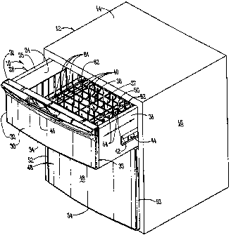
Figure 1 is a perspective view of the double
dishwasher of the present invention.
Figure 2 is a perspective view showing the upper
drawer partially removed from the upper washing
compartment.
Figure 3 is a front elevational view showing the
hinged door in its opened position providing access to
the lower washing compartment.
2

CA 02344571 2001-03-19
WO 00/16681 PCT/US99/21127
DETAILED DESCRIPTION OF THE PREFERRED EMBODIMENT
Referring to the drawings a dishwasher 10 includes
a cabinet 12 having a top wall 14, sidewalls 16, 18,
and a bottom wall 20. An intermediate wall 22 divides
the cabinet into an upper washing compartment 24, and a
lower washing compartment 26. While the two
compartments are shown in upper and lower relation to
one another it is also possible to orient them
differently, for example side by side.
Mounted within the upper compartment 24 is a
drawer 28 having an upper door 30 at its front. Upper
door 30 includes a top edge 31, side edges 32, 33, and
a bottom edge 34. Drawer 28 also includes sidewalls
35, 36, a bottom wall 37, and a rear wall (not shown).
Upper door 30 provides the front wall for the drawer
28. Within the drawer 38 is a rack 38 for supporting
dishes or other items to be washed. The structure of
the rack may vary without detracting from the
invention, but such racks usually contain tines 40
which help support the items to be washed.
The particular dishwashing apparatus within drawer
28 may vary according to any number of conventional
washing devices. Rotating arms, sprayers, and other
types of dishwasher actions may be provided in the
drawer 28. Figure 2 shows a pair of tubes 62, having
spray perforation 64 therein for spraying cleaning
fluid on the items to be washed. Tubes 62 are adapted
to rotate about their longitudinal axis and are
connected to a source of pressurized fluid (not shown).
Drawer 28 also includes a side track 42 having a
roller 44 mounted therein so that the drawer can be
rolled from its closed position shown in Figures 1 and
3, to its opened position shown in Figure 2. A control
panel 46 is provided adjacent the upper edge 31 of door
30. Also a handle 47 (Figure 3) is provided for
3

CA 02344571 2001-03-19
WO 00/16681 PCT/US99/21127
permitting grasping of the door 30 to roll it between
its closed and open positions.
A lower door 48 includes a top edge 50, side edges
52, 53, and a bottom edge 54. Door 48 is hinged
adjacent its bottom edge 54 for hinged movement from
the pos=a.:~ion shown in Figure 1 to the position shown in
Figure 3.
As can be seen in Figure 3, the lower compartment
26 icludes a rack 56 mounted therein for supporting
items to be washed. Rack 56 is suspended for rolling
movement by rollers 58 so that it may be rolled
inwardly and outwardly from the washing compartment 26
in a conventional manner. Door 48 includes a handle 60
(Figure 1) for permitting the grasping of the door to
move it from its closed to its open positions.
Conventional upper and lower washing arms 66, 68,
as well as a central spray tower 70, are shown for
spraying the items within the lower compartment 26.
There are many types of washing apparatus well known in
the art which could be used in both the upper
compartment and the lower compartment.
In use, items to be washed are placed in the lower
compartment. and while those dishes are being washed,
additional dirty dishes or items can be placed in the
upper compartment. Also, because the upper compartment
is of a smaller size, smaller batches of items to be
washed can be placed in the upper compartment, thereby
adding to the efficiency of the washing machine and
minimizing the amount of water and energy needed to
wash a small batch of dishes.
In the drawings and specification there has been
set forth a preferred embodiment of the invention, and
although specific terms are employed, these are used in
a generic and descriptive sense only and not for
purposes of limitation. Changes in the form and the
4

CA 02344571 2001-03-19
WO 00/16681 PCT/US99/21127
proportion of parts as well as in the substitution of
equivalents are contemplated as circumstances may
suggest or render expedient without departing from the
spirit or scope of the invention as further defined in
the following claims.
~~'.>
5

Representative Drawing
A single figure which represents the drawing illustrating the invention.
Administrative Status

2024-08-01:As part of the Next Generation Patents (NGP) transition, the Canadian Patents Database (CPD) now contains a more detailed Event History, which replicates the Event Log of our new back-office solution.

Please note that "Inactive:" events refers to events no longer in use in our new back-office solution.

For a clearer understanding of the status of the application/patent presented on this page, the site Disclaimer , as well as the definitions for Patent , Event History , Maintenance Fee  and Payment History  should be consulted.

Event History

Description Date
Time Limit for Reversal Expired 2017-09-14
Letter Sent 2016-09-14
Grant by Issuance 2004-08-03
Inactive: Cover page published 2004-08-02
Inactive: Final fee received 2004-05-20
Pre-grant 2004-05-20
Notice of Allowance is Issued 2004-03-01
Letter Sent 2004-03-01
Notice of Allowance is Issued 2004-03-01
Inactive: Approved for allowance (AFA) 2004-02-19
Amendment Received - Voluntary Amendment 2003-09-08
Inactive: S.30(2) Rules - Examiner requisition 2003-07-18
Letter Sent 2001-06-20
Inactive: Cover page published 2001-06-13
Inactive: First IPC assigned 2001-06-05
Inactive: Courtesy letter - Evidence 2001-06-05
Inactive: Acknowledgment of national entry - RFE 2001-05-28
Inactive: Single transfer 2001-05-24
Application Received - PCT 2001-05-22
All Requirements for Examination Determined Compliant 2001-03-19
Request for Examination Requirements Determined Compliant 2001-03-19
Application Published (Open to Public Inspection) 2000-03-30

Abandonment History

There is no abandonment history.

Maintenance Fee

The last payment was received on 2003-08-22

Note : If the full payment has not been received on or before the date indicated, a further fee may be required which may be one of the following

  • the reinstatement fee;
  • the late payment fee; or
  • additional fee to reverse deemed expiry.

Patent fees are adjusted on the 1st of January every year. The amounts above are the current amounts if received by December 31 of the current year.
Please refer to the CIPO Patent Fees web page to see all current fee amounts.

Owners on Record

Note: Records showing the ownership history in alphabetical order.

Current Owners on Record
MAYTAG CORPORATION
Past Owners on Record
DOUGLAS RINGGER
JUDA CORDLE
RODNEY WELCH
STEPHEN BIRKENHOLTZ
Past Owners that do not appear in the "Owners on Record" listing will appear in other documentation within the application.
Documents

To view selected files, please enter reCAPTCHA code :


To view images, click a link in the Document Description column. To download the documents, select one or more checkboxes in the first column and then click the "Download Selected in PDF format (Zip Archive)" or the "Download Selected as Single PDF" button.

List of published and non-published patent-specific documents on the CPD .

If you have any difficulty accessing content, you can call the Client Service Centre at 1-866-997-1936 or send them an e-mail at CIPO Client Service Centre.


Document
Description 
Date
(yyyy-mm-dd) 
Number of pages   Size of Image (KB) 
Representative drawing 2001-06-12 1 18
Claims 2003-09-07 2 57
Description 2003-09-07 7 258
Abstract 2001-03-18 1 63
Description 2001-03-18 7 267
Claims 2001-03-18 2 73
Drawings 2001-03-18 3 91
Reminder of maintenance fee due 2001-05-27 1 111
Notice of National Entry 2001-05-27 1 202
Courtesy - Certificate of registration (related document(s)) 2001-06-19 1 112
Commissioner's Notice - Application Found Allowable 2004-02-29 1 161
Maintenance Fee Notice 2016-10-25 1 177
Correspondence 2001-05-27 1 23
PCT 2001-03-18 11 421
Fees 2003-08-21 1 30
Fees 2001-08-20 1 31
Fees 2002-08-14 1 31
Correspondence 2004-05-19 1 29
Fees 2004-08-16 1 25
Fees 2005-08-10 1 28
Fees 2006-09-07 1 28