Language selection

Search

Patent 2344600 Summary

Third-party information liability

Some of the information on this Web page has been provided by external sources. The Government of Canada is not responsible for the accuracy, reliability or currency of the information supplied by external sources. Users wishing to rely upon this information should consult directly with the source of the information. Content provided by external sources is not subject to official languages, privacy and accessibility requirements.

Claims and Abstract availability

Any discrepancies in the text and image of the Claims and Abstract are due to differing posting times. Text of the Claims and Abstract are posted:

  • At the time the application is open to public inspection;
  • At the time of issue of the patent (grant).
(12) Patent Application: (11) CA 2344600
(54) English Title: CABLE CONNECTOR AND KIT FOR ASSEMBLING THE SAME
(54) French Title: CONNECTEUR DE CABLE ET NECESSAIRE D'ASSEMBLAGE DE CE CONNECTEUR
Status: Deemed Abandoned and Beyond the Period of Reinstatement - Pending Response to Notice of Disregarded Communication
Bibliographic Data
(51) International Patent Classification (IPC):
  • H01R 13/648 (2006.01)
  • H01R 13/514 (2006.01)
  • H01R 13/652 (2006.01)
  • H01R 13/658 (2011.01)
(72) Inventors :
  • VAN ZANTEN, ALBERTUS
(73) Owners :
  • F.C.I. - FRAMATOME CONNECTORS INTERNATIONAL
(71) Applicants :
  • F.C.I. - FRAMATOME CONNECTORS INTERNATIONAL (France)
(74) Agent: BKP GP
(74) Associate agent:
(45) Issued:
(22) Filed Date: 2001-04-19
(41) Open to Public Inspection: 2001-10-28
Examination requested: 2004-03-31
Availability of licence: N/A
Dedicated to the Public: N/A
(25) Language of filing: English

Patent Cooperation Treaty (PCT): No

(30) Application Priority Data:
Application No. Country/Territory Date
1015059 (Netherlands (Kingdom of the)) 2000-04-28

Abstracts

English Abstract


The invention pertains to a cable connector compris-
ing a housing, which forms a shielding and/or which is pro-
vided with a shielding, and at least one connector module
placed within the housing, which module comprises a body of
an electrically insulating material, a circuit substrate
comprising a grounding layer and one or more terminals
mounted on the circuit substrate. The said shielding of the
housing is electrically connected to the grounding layer of
the circuit substrate, thus improving the grounding of the
entire cable connector.


Claims

Note: Claims are shown in the official language in which they were submitted.

7
Claims
1. Cable connector comprising a housing, which forms
a shielding and/or which is provided with a shielding, and
at least one connector module placed within the housing,
which module comprises a body of an electrically insulating
material, a circuit substrate comprising a grounding layer
and one or more terminals mounted on the circuit substrate,
characterised in that the said shielding of the housing is
electrically connected to the grounding layer of the circuit
substrate and in that the housing contains a resilient clip
of a electrically conducting material, which clip estab-
lishes electrical contact between the grounding layer of the
circuit substrate and the shielding of the housing or, upon
connection of the cable connector to a counterpart, a
grounding layer comprised in that counterpart.
2. Cable connector according to claim 1, wherein the
housing comprises an inwardly protruding notch that contacts
the grounding layer of the circuit substrate and that estab-
lished electrical contact between the shielding and the said
grounding layer.
3. Cable connector according to claim 2, wherein the
body of the connector module comprises a slit or opening for
accommodating the protruding notch.
4. Cable connector according any one of the preced-
ing, wherein the housing contains two or more circuit sub-
strates one above the other and each comprising a grounding
layer and wherein the resilient clip abuts the grounding
layers of at least two circuit substrates.
5. Cable connector according to claim 4, wherein the
body of the connector module comprises a slit or opening for
accommodating that part of the clip that electrically con-
nects at least two of the grounding layers.
6. Cable connector according to claim 4 or 5,
wherein the housing comprises a further resilient clip that
electrically connects the outermost of the grounding layers

8
that are connected by means of the first resilient clip to
the shielding of the housing.
7. Cable connector according to any one of the pre-
ceding claims, wherein the connector is attached to a cable
comprising a shielding and wherein the shielding of the
housing is electrically connected to the shielding of the
cable.
8. Kit for assembling a connector according to any
one of the preceding claims, comprising a housing which
forms a shielding or which is provided with a shielding, and
at least one connector module placed or to be placed within
the housing, which module comprises a body of an electri-
cally insulating material, a circuit substrate comprising a
grounding layer and one or more terminals mounted on the
circuit substrate, characterised in that the housing com-
prises an inwardly protruding notch and/or the kit contains
a resilient clip, wherein the notch and/or the clip, upon
assembly of the connector, serve to establish electrical
contact between the shielding and the grounding layer or
layers.

Description

Note: Descriptions are shown in the official language in which they were submitted.


CA 02344600 2001-04-19
NL 2901-Aa/rp
Cable connector and kit for assembling the same.
The invention pertains to a cable connector compris-
ing a housing, which forms a shielding and/or which is pro-
vided with a shielding, and at least one connector module
placed within the housing, which module comprises a body of
an electrically insulating material, a circuit substrate
comprising a grounding layer and one or more terminals
mounted on the circuit substrate.
Such cable connectors are known, for example from EP
0 736 931, and are used, for instance, to provide a cable-
to-panel electrical connection between a cable and a printed
circuit board (PCB) of, for instance, a telephone exchange
device or the like. Cable connectors of this kind allow op-
eration at high speed.
In modern applications, a permanent need exists for
increased speed (e. g., gigabits and beyond) and enhanced
signal integrity and it is therefore desirable to further
improve, amongst other things, the grounding of cable con-
nectors.
i
To this end, the connector of the present invention
i 20 is characterised in that the said shielding of the housing
is electrically connected to the grounding layer of the cir-
cuit substrate and in that the housing contains a resilient
I
- clip of a electrically conducting material, which clip es-
tablishes electrical contact between the grounding layer of
the circuit substrate and the shielding of the housing or,
upon connection of the cable connector to a counterpart, a
grounding layer comprised in that counterpart.
Thus, it appeared that the overall grounding of the
cable connector can be improved considerably and the detri
mental effects of, for instance, phase differences in dif

CA 02344600 2001-04-19
2
ferential pairs (which are frequently used in this kind of
cable connector) are suppressed more effectively.
In a very robust and cost effective embodiment of
the present invention, the housing comprises an inwardly
protruding notch that contacts the grounding layer of the
circuit substrate and that establishes electrical contact
between the shielding of the housing and the said grounding
layer. Accordingly, it is preferred that the body of the
connector module comprises a slit or opening for accommodat-
ing the protruding notch.
In a further embodiment of the present invention,
the housing contains a resilient clip of an electrically
conducting material, which clip establishes electrical con-
tact between the grounding layer of the circuit substrate on
i 15 the one hand and the shielding of the housing or, upon con-
nection of the cable connector to a counterpart, a grounding
(layer) comprised in that counterpart on the other hand.
Thus, the grounding of a connector and/or a connection es-
tablished using the connector of the present invention is
substantially improved.
The invention also pertains to a kit for assembling
the above-described cable connector, wherein the housing
comprises an inwardly protruding notch and/or the kit con-
tams a resilient clip and wherein the notch and/or the
clip, upon assembly of the connector, serve to establish
electrical contact between the shielding and the grounding
layer.
The invention will be further explained with refer-
ence to the drawings, in which two embodiments of the con-
nector according to the present invention are schematically
shown.
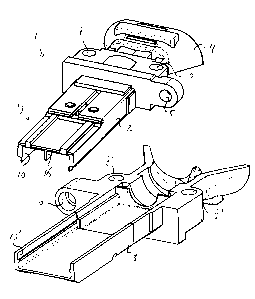
Figure 1 is an exploded view of a housing of a first
embodiment of a cable connector in accordance with the pres-
ent invention.

CA 02344600 2001-04-19
3
Figure 2 is an isometric view of connector module
intended for use in combination with the housing according
to Figure 1.
Figure 3 is an exploded view of a second embodiment
of a cable connector in accordance with the present inven-
tion.
Figure 4 and 5 show two connector modules for use in
the cable connector of Figure 3, respectively with and with-
out an additional outer housing.
Figures 6 and 7 each show a clip for use in the ca-
ble connector of Figure 3.
Figure 1 shows a housing 1 of a cable connector ac-
cording to the present invention, which housing 1 consists
of an upper part 2 and a lower part 3. The housing 1 may be
manufactured of a metal, such as aluminium, and thus inher-
i ently function as a shielding against electromagnetic inter-
ference (EMI). Alternatively, the housing may be manufac-
tured of an electrically insulating material, e.g., a Alas-
tic material, such as a nylon or a liquid crystalline poly-
i 20 mer. In that case, the housing should be provided with EMI
I shielding on its outer surface. Such an EMI shielding may,
for instance, consist of an electrically conducting metal
coating. Such coatings are known to the persons skilled in
the art and may, for instance, comprise a copper layer with
a thickness of say 1 - 2 ~m on which a nickel or aluminium
layer of say 2 - 3 ~m has been deposited. The shielding of
the housing 1 should, upon attachment of the connector to a
cable, preferably be electrically connected to the shielding
of the cable, such as a braid.
The rear end of the connector 1 comprises a conical
sleeve 4 for receiving a cable. Both the upper part 2 and
the lower part 3 of the housing 1 are provided with a hole 5
resp. 6 for receiving a means, such as a screw or the like,
for attaching the connector to a counterpart. Through-holes
7, 7', 8, 8' are provided for securing the two parts 2, 3
together.

CA 02344600 2001-04-19
4
The front end 9 of the housing 1 comprises a cavity
' 10, 10' for receiving two stacked connector modules 11, one
of which is shown in Figure 2. The cable connector module 11
comprises a body 12 of an electrically insulating material.
The body 12 is preferably formed by moulding a polymeric
resin having appropriate strength and heat resistance char-
I acteristics, such as nylon 66 or a liquid crystalline poly-
mer. The front edge of the body 12 defines a mating inter-
face for receiving terminals of a counterpart through a plu-
rality of openings 13. For example, the connector module 11
;, could match with one column of an array of terminal pins ar-
ranged in rows and columns in a pin header backplane connec-
' tor, with such pins generally being inserted into the open-
ings in a direction parallel to the longitudinal axis of the
i 15 connector module 11.
A circuit substrate 14, i.e. preferably a generally
planar printed circuit board (PCB), is received on one of
the major sides of the body 12. The circuit substrate 14 is
retained and located with respect to the body 12 by a secur-
ing/locating post (not shown) extending from the body 12 and
I
receivable in an opening (also not shown) in the circuit
substrate 14. The circuit substrate 14 may be of multi-layer
construction and incorporates a grounding layer or ground
plane, which can be either located on the surface that abuts
the body 12 or on the surface that faces away from the body
12. The connector module 11 further comprises four recepta-
cle terminals located behind the openings 13 in the mating
surface. This particular example shows an 1X4 connector mod-
ule, two of which are to be used in the housing 1 of Figure
1. However, other modules, for instance, a 2x4 module, or a
2x6 module or two 2x6 modules may be employed. As a matter
of course, the shape and size of the cavity 10, 10' should
be adapted to receive a selected (stack of) connector mod-
ule (s) .
The body 12 is further equipped with a notch 15 on
its upper surface which serves to position the connector

CA 02344600 2001-04-19
I
module 11 with respect to the housing 1 of the connector or
with respect to a further cable connector module placed on
top of this connector module (as shown in Fig. 5).
The upper part 2 of the housing 1 of the connector
5 comprises an inwardly protruding notch 16 near its mating
end, whereas the cable connector module 11 is equipped with
a slit 17 for receiving the said protruding notch 16. The
notch 16 is sufficiently long to abut the ground plane of
the circuit substrate 14 or, if the ground plane is located
on the surface that faces away from the body 12 and the
notch 16, to abut a plated through-hole or an electrical
lead trough the circuit substrate 14. Thus, the notch 16 es-
tablishes electrical contact between the shielding of the
housing 1 and the said grounding layer.
Figure 3 shows a (disassembled) second embodiment of
I the cable connector according to the present invention. This
connector 21 again comprises a housing having an upper part
I
22 and a lower part 23. The said parts 22, 23 each comprise
two through-holes 24, 24',25, 25' for securing the two parts
' 20 22, 23 together and through-holes 26, 27 for attaching the
connector 21 to a counterpart. A cable connector module 28
j can be positioned between the parts 22, 23. To this end, the
' cable connector module 28 comprises four securing/locating
posts 29 which are receivable in openings 30 in the upper
and lower parts 22, 23.
As shown in more detail in Figure 4, the cable con-
nector module 28 comprises an outer housing 31 of an elec-
trically insulating material such as the aforementioned
plastic materials. The outer housing 31 comprises alignment
rails 32, 32' for aligning the connector 21 with respect to
a counterpart. The outer housing 31 contains two 1x4 connec-
tor modules 34 similar to the one shown in Figure 2.
Figure 5 shows the connector module 28 without the
outer housing 31. Each of the 1x4 modules 34 comprises a
circuit substrate 3S, each of which comprises a grounding
layer 36 covering its lower surface.

CA 02344600 2001-04-19
i 6
A clip 38, as shown in Figure 6, has been mounted
' against the lower surface, i.e. the grounding layer 36, of
the lower of the two connector modules 34. The clip 38 com-
prises a semicircular element 39, which abuts the grounding
layer of the upper of the two connector modules. It further
comprises two protrusions 40, which abut the grounding layer
36, as well as two resilient arms 41 for contacting, upon
connection of the connector 21 to a counterpart, a grounding
layer in the said counterpart.
To further enhance the grounding of the connector
21, a connecting element 42, as shown in detail in Figure 7,
is provided which is manufactured of an electrically con-
ducting material. Upon assembly of the connector 21, the
connecting element 42 abuts the grounding layer of the upper
connector module by means of two protrusions 43, 44 and is
electrically connected to the upper part 22 of the housing
of the connector 21 by means of extensions 45, 46.
It will be clear from the above embodiments that the
connectors according to the invention exhibit improved
grounding, which has been extended to components contained
in the connector as well as to a counterpart of the connec-
tor.
The invention is not restricted to the above-
described embodiments, which can be varied in a number of
ways within the scope of the claims.

Representative Drawing
A single figure which represents the drawing illustrating the invention.
Administrative Status

2024-08-01:As part of the Next Generation Patents (NGP) transition, the Canadian Patents Database (CPD) now contains a more detailed Event History, which replicates the Event Log of our new back-office solution.

Please note that "Inactive:" events refers to events no longer in use in our new back-office solution.

For a clearer understanding of the status of the application/patent presented on this page, the site Disclaimer , as well as the definitions for Patent , Event History , Maintenance Fee  and Payment History  should be consulted.

Event History

Description Date
Inactive: IPC from PCS 2022-09-10
Inactive: First IPC from PCS 2022-09-10
Inactive: IPC from PCS 2022-09-10
Inactive: IPC expired 2011-01-01
Time Limit for Reversal Expired 2008-04-21
Application Not Reinstated by Deadline 2008-04-21
Deemed Abandoned - Failure to Respond to Maintenance Fee Notice 2007-04-19
Amendment Received - Voluntary Amendment 2006-12-07
Inactive: S.30(2) Rules - Examiner requisition 2006-07-12
Inactive: IPC from MCD 2006-03-12
Amendment Received - Voluntary Amendment 2004-07-16
Letter Sent 2004-04-14
Request for Examination Received 2004-03-31
All Requirements for Examination Determined Compliant 2004-03-31
Request for Examination Requirements Determined Compliant 2004-03-31
Inactive: Office letter 2002-12-13
Revocation of Agent Requirements Determined Compliant 2002-12-13
Appointment of Agent Requirements Determined Compliant 2002-12-13
Appointment of Agent Request 2002-11-27
Revocation of Agent Request 2002-11-27
Appointment of Agent Request 2002-11-25
Revocation of Agent Request 2002-11-25
Inactive: Cover page published 2001-10-28
Application Published (Open to Public Inspection) 2001-10-28
Letter Sent 2001-07-11
Inactive: IPC assigned 2001-06-06
Inactive: First IPC assigned 2001-06-06
Inactive: Single transfer 2001-06-05
Inactive: Courtesy letter - Evidence 2001-05-29
Inactive: Filing certificate - No RFE (English) 2001-05-22
Application Received - Regular National 2001-05-22

Abandonment History

Abandonment Date Reason Reinstatement Date
2007-04-19

Maintenance Fee

The last payment was received on 2006-04-12

Note : If the full payment has not been received on or before the date indicated, a further fee may be required which may be one of the following

  • the reinstatement fee;
  • the late payment fee; or
  • additional fee to reverse deemed expiry.

Patent fees are adjusted on the 1st of January every year. The amounts above are the current amounts if received by December 31 of the current year.
Please refer to the CIPO Patent Fees web page to see all current fee amounts.

Fee History

Fee Type Anniversary Year Due Date Paid Date
Application fee - standard 2001-04-19
Registration of a document 2001-06-05
MF (application, 2nd anniv.) - standard 02 2003-04-21 2003-03-27
MF (application, 3rd anniv.) - standard 03 2004-04-19 2004-03-31
Request for examination - standard 2004-03-31
MF (application, 4th anniv.) - standard 04 2005-04-19 2005-04-13
MF (application, 5th anniv.) - standard 05 2006-04-19 2006-04-12
Owners on Record

Note: Records showing the ownership history in alphabetical order.

Current Owners on Record
F.C.I. - FRAMATOME CONNECTORS INTERNATIONAL
Past Owners on Record
ALBERTUS VAN ZANTEN
Past Owners that do not appear in the "Owners on Record" listing will appear in other documentation within the application.
Documents

To view selected files, please enter reCAPTCHA code :


To view images, click a link in the Document Description column. To download the documents, select one or more checkboxes in the first column and then click the "Download Selected in PDF format (Zip Archive)" or the "Download Selected as Single PDF" button.

List of published and non-published patent-specific documents on the CPD .

If you have any difficulty accessing content, you can call the Client Service Centre at 1-866-997-1936 or send them an e-mail at CIPO Client Service Centre.


Document
Description 
Date
(yyyy-mm-dd) 
Number of pages   Size of Image (KB) 
Representative drawing 2001-09-18 1 15
Drawings 2001-04-18 3 99
Claims 2001-04-18 2 90
Abstract 2001-04-18 1 20
Description 2001-04-18 6 323
Description 2006-12-06 7 322
Claims 2006-12-06 3 82
Filing Certificate (English) 2001-05-21 1 164
Courtesy - Certificate of registration (related document(s)) 2001-07-10 1 112
Reminder of maintenance fee due 2002-12-22 1 106
Acknowledgement of Request for Examination 2004-04-13 1 176
Courtesy - Abandonment Letter (Maintenance Fee) 2007-06-13 1 176
Correspondence 2001-05-21 1 25
Correspondence 2002-11-26 3 91
Correspondence 2002-11-24 3 89
Correspondence 2002-12-12 1 14
Correspondence 2002-12-12 1 16
Fees 2003-03-26 1 35
Fees 2004-03-30 1 30
Fees 2005-04-12 1 29
Fees 2006-04-11 1 31