Note: Descriptions are shown in the official language in which they were submitted.
CA 02344692 2001-03-19
WO 00130915 PCTIUS99113317
POfnIER STEERING SYSTEM WITH CONTROLLED CENTERING
FIELD OF THE INVENTION
This invention relates to vehicle steering systems, and more
particularly to an improved power steering assembly for
controlling the steerable wheels of a vehicle such as an
automobile, a motor home, a bus, a truck or the like, so that a
steering position for the steerabie wheels is controlled both at
center and away from center in spite of spurious influences on
the steerable wheels, such as those caused by variable cross
winds, crowned or slanted roadways, or other factors tending to
adversely affect steering of the vehicle by the driver.
BACKGROUND OF THE INVENTION
Vehicles with steering systems having positive caster
generally track relatively straight ahead and resist steering
inputs away from center, including those of the driver, provided
that the roadway they are travelling on is smooth and is not
slanted or crowned. Such positive caster is provided by positive
caster offset, which is also known as mechanical trail. Caster
offset is the distance from the ground intersection point of a
pivot line drawn through the pivot axis of a steerable wheel to
a contact point at the center of the area over which the wheel
contacts the ground. The pivot axis of a steerable wheel of a
motor vehicle is usually provided by a "king pin". Because the
contact point of a steerable wheel with positive caster trails
the pivot line point of the wheel, side forces cause the wheel
to turn in the direction that the force is being applied. A good
example of this is the way in which the castered wheels on the
SUBSTITUTE SHEET (RULE 26)
CA 02344692 2001-03-19
WO 00/3U915 PCT/US99/133I7
front of a shopping cart are easily turned in the direction of
applied force.
The adverse effects described below are some of the negative
aspects of achieving steering stability with positive caster
offset. Because of the side force applied by gravitational pull
on a slanted or crowned highway, positive caster offset causes
a motor vehicle tc freely turn to the low side, creating a
steering wheel pull that requires counteractive steering input
from the driver to keep the vehicle from leaving the highway.
The amount of driving fatigue that is directly caused by positive
caster offset under these conditions may be appreciated by
considering the many millions of miles driven by truck drivers
and other motorists each day on crowned or slanted highways.
Another fatiguing driving condition that may be encountered
by a motorist is that of controlling a crosswind steering input.
The amount of adverse steering input caused by crosswinds is
directly related to the amount of positive caster offset, which
is a classic example of having to balance a benefit with a
detriment. The small amount of stability gained from castering
the steerable wheels on a non-windy day may be paid for many
times over when driving in a crosswind because of the
destabilizing effect of the crosswind when combined with positive
caster offset. Positive caster offset also allows steering
inputs from rutted and other imperfect roadway surfaces to steer
back against the driver and thereby cause road wander, which is
a universal driving complaint, particularly by driver's of heavy
vehicles such as trucks and motor homes.
2
SUBSTITUTE SHEET (RULE 26)
CA 02344692 2001-03-19
WO 00/30915 PCT/US99/133I7
For the lack of a more advanced method, steerable wheel
castering has been accepted by the industry as a low-cost method
of achieving steerable wheel returnability. Thus, large, heavy
over-the-road vehicles are presently provided with generous
amounts of positive caster. Not much thought has been given to
the self-defeating side effects of steerable wheel castering.
Instead, the lack of directional stability is blamed on the size
and weight of the vehicle.
As the size and weight of over-the-road vehicles increases,
the need for directional stability becomes more important.
Learning to drive a heavy vehicle means learning to control the
back steer caused by the adverse side effects of steerable wheel
castering. The failure of the industry to recognize the critical
need to provide directional stability by replacing steerable
wheel cantering with another method of achieving steerable wheel
returnability may go down in history as one of the longest
enduring heavy vehicle design oversights.
The lack of directional stability is fundamentally the
reason that heavy vehicle driving is much more stressful than it
otherwise needs to be. Keeping a heavy vehicle, that is lacking
in directional stability, tracking straight and under control for
extended periods of time is a major cause of driving fatigue and
related accident potential. The failure of numerous driver
fatigue and alertness studies to consider the contribution made
by "driving" fatigue in the overall evaluation is indicative of
the wide-spread failure of the industry to recognize the lack of
directional stability as the major cause of driver fatigue
resulting from driving fatigue. Accordingly, a dramatic
3
SUBSTITUTE SHEET (RULE 26)
CA 02344692 2001-03-19
WO 00/30915 PCT/US99/13317
reduction in driver fatigue may be made by making heavy over-the-
road vehicles directionally stable and thereby significantly
reducing driving fatigue.
The term "directional stability" does not legitimately apply
to the current production of heavy vehicles because they are, in
fact, not directionally stable. The lack of heavy vehicle
directional stability is not the fault of the steering gear. The
purpose of past improvements in the art of steering gears and
other steering components has been to make it easier for the
driver to control the unstable behavior of cantered steerable
wheels. Irrespective of such refinements in the steering gear
and related components, when the steerable wheels are allowed to
caster, the driver will still have to make the same excessive
number of steering corrections to control road wander, slanted
road steering wheel pull, and down wind steerable whee l
cantering.
Thus, a highly important consideration that has long been
overlooked by the industry is that steerable wheel cantering is
directly responsible for road wander, crowned road steering wheel
pull and cross wind steering problems . Keeping an unstable heavy
vehicle tracking straight and under control currently requires
an inordinate amount of driver steering corrections to counteract
the adverse side effects of cantered wheels. The repetitive task
of making thousands of precise steering corrections mile after
mile weighs heavily on a driver' s physical and mental well-being,
and may result in extreme driving fatigue. Thus, vehicle
directional stability especially for heavy vehicles can only be
achieved by stabilizing the on-center behavior of the steerable
4
SUBSTITUTE SHEET (RULE 26)
CA 02344692 2001-03-19
WO 00/30915 PCT/US99/13317
wheels with a more suitable method than the traditional steerable
wheel cantering used on all current production vehicles.
SUMMARY OF TF~:E INVENTION
It is believed that directional stability of motor vehicles,
particularly heavy vehicles, can only be achieved by stabilizing
the return-to-center and on-center behavior of the steerable
wheels with a more suitable method than the traditional steerable
wheel cantering used on all current production vehicles. When
the steerable wheels are prevented from cantering, there is a
considerable reduction in the amount of corrective steering
required by the vehicle driver, resulting in a major reduction
in driving fatigue. Therefore, the purpose of the present
invention is to provide on-center and return-to-center
improvements in power steering systems fox over-the-road vehicles
by adding a steerable wheel holding feature to prior art power
steering systems.
The primary function of present state of the art power
steering systems is to assist the driver when turning away from
center. When the driver releases the steering wheel after
turning, a rotary valve in the steering gear returns to neutral.
When this rotary valve is in its neutral position, the power
steering gear has no influence on the direction of the steerable
wheels. This arrangement or operating mode is called "free
return" and allows the influence of the road surface and the
steering geometry to cause the steerable wheels to return to a
center position. In the center position, conventional power
steering units do not control the steerable wheels except in
SUBSTITUTE SHEET (RULE 26)
CA 02344692 2001-03-19
WO 00/30915 PCTIUS99/13317
response to corrective steering inputs transmitted from the
driver through the steering shaft.
The present invention may be used to eliminate the free
return mode of operation used in existing power assisted steering
assemblies. When the free return mode is no longer provided, the
steerable wheels will no longer be influenced by spurious
steering inputs from the road surface and/or from the steering
geometry. Instead, the steerable wheels will be kept tracking
straight ahead in the an-center position, and will respond only
to intentional steering inputs by the vehicle driver.
Instead of relying on positive castering, steering wheel
returnability after a turning movement is provided by a steering
shaft centering assembly, such as that described and shown in my
U.S. Patent No. 5,816,594 issued October 6, 1998, the entire
contents of which are expressly incorporated herein by reference.
As described in this patent, the return to center influence of
the centering assembly is preferably increased when the vehicle
speed is increased to optimize vehicle directional stability.
The combination of the present disclosure with that in my prior
patent provides an overall power steering system that achieves
directional stability in both light and heavy motor vehicles.
The invention therefore provides improved on-center and
away-from-center control of the steering shaft and the steerable
wheels, and significantly reduces driver fatigue resulting from
driving fatigue because it results in a major reduction in driver
steering inputs. Any positive castering present is overridden
by this steering shaft control. The invention also eliminates
the need for any positive castering by providing directional
6
SUBSTITUTE SKEET (RULE 26)
CA 02344692 2001-03-19
WO 00/30915 PCTIUS99113317
stability of the steerable wheels when there is no positive
caster, i , a . , a caster angle of zero degrees ( 0°) . Thus, on-
center tracking of the steerable wheels is achieved by a means
that does not have the deficiencies inherent in positive caster
offset, and that substantially reduces the need for corrective
steering inputs from the vehicle driver. The positive on-center
feel of such a directionally stable vehicle provides a new level
of driveability for' motor vehicles, including automobiles,
trucks, buses, campers and motorized homes. The invention thus
attains new levels of directional stability and driveability,
which reduce driver fatigue to a level that c«nnot be achieved
by conventional positive caster centering.
The replacement of steerable wheel castering with the power
centering technology of the present invention has a number of
additional advantages. These include precision on-center
directional stability of the steerable wheels that make the
vehicle more comfortable to drive a corresponding reduction in
accident potential due to the considerable reduction in driving
fatigue, improvement in steerable wheel blowout protection and
related safety, improvement. in the tire wear pattern of the
steerable wheels that increases tire life and reduces maintenance
costs, a stable non-swaying ride that improves passenger comfort
particularly in buses and other large vehicles, and lower
insurance costs due to significant improvements in overall
vehicle safety.
The foregoing advantages are achieved by an on-center
holding system incorporated into the power steering system of the
present invention. The power steering system comprises a power
7
SUBSTITUTE SHEET (RULE 26)
CA 02344692 2001-03-19
WO 00/30915 PCT/US99/133I7
unit, a valve unit and a centering unit. The power unit
comprises a power piste~~ for actuating the pitman arm of a
vehicle steering system. The power piston reciprocates in a
power cylinder to provide power assisted steering and is driven
by a worm connected to the steering shaft for rotation in
response to either the centering unit or the vehicle steering
wheel. The valve unit is connected between the worm of the power
unit and a steering shaft segment from the centering unit. A
rotary valve member is f_xed to the steering shaft segment and
rotatably received in the bore of a sleeve fixed to the worm.
The sleeve is connected ~o the rotary valve member through a
torsion rod arranged to actuate a pair of spool valves formed by
valuing elements on the body of the rotary valve and in the bore
of the sleeve.
The spool valves axe «rranged in series to provide hydraulic
fluid pressure to the power unit only while the steering shaft
is being turned by either the steering wheel ar the centering
unit. Thus, it is only during such turning movement that
pressurize d hydraulic fluid is supplied from the first spool
valve to the second spool valve and from the second spool valve
to the power cylinder. In the absence of such turning movement,
the first spool valve recirculates pressurized hydraulic fluid
from an hydraulic pump to an hydraulic fluid reservoir. At least
one of the embodiments prevents free return of the power unit to
center after an away-from-center turning movement. In this
embodiment, the returnability of the steering system to its
center position is dependent upon rotation of the steering shaft
by either an automatic return force from the centering unit or
8
SUBSTTTUTE SHEET (RULE 26)
CA 02344692 2001-03-19
WO 00/30915 PCT/US99/133I7
a manual return force from turning of the steering wheel towards
center by the vehicle driver. However, since automatic return
to center is always available from the centering unit, there is
no need for manual return by the driver. The invention thereby
provides improved on-center control of the steering shaft and the
steerable wheels, and significantly reduces driving fatigue
because it results in a significant reduction in the driver
steering inputs required for on-center tracking of the steerable
wheels.
The preferred embodiments of the present invention may also
include the following features: a resistance force for opposing
steering movement away from center, a return force for return to
center of sufficient magnitude to overcome spurious steering
inputs, remotely variable levels of resistance force and return
force through a predetermined range of turning movement, a
remotely trimmable center position, no substantial overshoot, a
fail-safe mode for disabling the centering assembly in the
absence of power steering, precision centering, dampening of
erratic steering movements, compact size, economical to
manufacture and install, utility for old and new vehicles with
power steering, and distinctive driver road feel.
BRIEF DESCRIPTION OF THE DRAS~IINGS
The invention, both as to its structure and operation, may
be further understood by reference to the detailed description
below taken in conjunction with the accampanying drawings in
which:.
9
SUBSTITUTE SHEET (RULE 26)
CA 02344692 2001-03-19
WO 00/30915 PCT/US99/13317
Fig. l is a fragmentary, partially sectional, left side
elevational view showing the interconnection of the main
component s of the invention;
Fig. 2 is a enlarged, partially sectional, plan view of the
valve unit of Fig. 1;
Fig. 3 is a transverse sectional view taken along line 3-3
of Fig. 2;
Fig. 4 is a transverse sectional view taken along Line 4-4
of Fig. 2;
Fig. 5 is a transverse sectional view taken along line 5-5
of Fig. 2;
Fig. 6 is a schematic diagram of the fluid and electrical
systems for operating the centering unit of Fig. 1, and includes
a left side elevational view in partial section showing
additional structural details of the centering unit, including
a trim assembly for trimming the center position of the steering
system.
Fig. 7 is a diagrammatic illustration of the power steering
system when the vehicle steering wheel is in its neutral
position;
Fig. 7A is an enlargement of the detail structure identified
by circle A in Fig. 7;
Fig. 8 is a diagrammatic illustration of the power steering
system during away-from-center movement of the steering wheel
toward a right turn position;
Fig. 9 is a diagrammatic illustration of the power steering
system when the steering wheel is held at a static right turn
position during a right turn of the vehicle;
SUBSTITUTE SHEET (RULE 26)
CA 02344692 2001-03-19
WO 00/30915 PCT/US99/I3317
Fig. 1Q is a diagrammatic illustration of the power steering
system during return-to-center movement of the steering shaft
from a right turn position in response to the centering unit of
Fig. 1 upon release of the steering wheel by the driver;
Fig. 11 is a diagrammatic illustration showing a
modification of the power steering system of the invention with
the vehicle steering system is in its center position;
Fig. 12 is a diagrammatic illustration of the modified power
steering system of Fig. 11 during away-from-center movement of
the steering wheel toward a left turn position; and,
Fig. 23 is a left side elevational view in partial section
showing the centering unit of the invention when the modified
power steering system is in the left turn position of Fig. 12.
DETAILED DESCRIPTION OF THE PREFERRED EMBODIMENTS
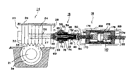
Referring to Fig. 1, the power steering assembly of the
present invention comprises a power unit generally designated 14,
a valve unit generally designated 16, and a centering unit
generally designated 18. These units are connected in series
between the shaft 21 of a conventional pitman arm 20 (Fig. 7) and
a steering column or shaft 22 on which is mounted the usual
steering wheel (now shown).
The power unit 14 includes a power piston 24 confined within
a power cylinder 26 between a right power chamber 28 and a left
power chamber 30. The power cylinder 26 has rack teeth 32
meshing with peripheral teeth 33 of a sector gear 34 fixed to or
integral with the, pitman arm shaft 21. Shaft 21 carries the
11
SUBSTITUTE SHEET (RULE Z6)
CA 02344692 2001-03-19
WO 00/30915 PCT/US99/1331?
pitman arm 20 that is connected through steering linkages (not
shown) to at least one steerable wheel of a vehicle.
Piston 24 has a bore that is helically grooved internally
in a manner complimentary to the helical groove of a power worm
36 received within the bore of piston 24. Balls confined and
traveling within the channel formed by the complimentary piston
and worm grooves constitute the connection between the piston and
the worm, and a return tube (not shown) is pravided to allow for
circulation of the balls in a manner well known in the art and
as shown, for example, in U.S. Patent No. 3,022,772, to Zeigler
et al., the entire contents of which are incorporated herein by
reference.
The power worm 36 has_a flanged base forming a sleeve 38
with a bore 40 for rotatably receiving a rotary valve member 42,
which in turn has a central chamber 44 for accommodating a
torsion rod 46. The distal end of the torsion rod is staked by
a pin 48 to an intermediate section of the power worm 36 between
its threaded portion 37 and its sleeve 38. The proximate end of
the torsion rod 46 is staked by a pin 49 to an end segment 47 of
the rotary valve member 42 projecting beyond the sleeve 38. The
rotary valve end segment 47 is connected to an end segment 56 of
the steering shaft 22 by a hollow coupling 50 having internal
splines engaging external splines 52 on the end segment 47 of
rotary valve member42. The opposite end of the coupling 50 is
staked by a pin 54 to the steering shaft end segment 56: The
steering shaft end segment 56 is an extension of steering shaft
22 as described further below in connection with the structural
details of the centering unit 28. Since the sleeve bore 40 and
12
SUBSTITUTE SHEET (RULE Z6)
CA 02344692 2001-03-19
WO 00/30915 PCT/US99/133I7
the central chamber 44 contain hydraulic fluid, the rotary valve
42 incudes fluid seals 58 and 59, and the torsion rod includes
a fluid seal 61. Each of these fluid seals may be of the O-ring
type.
Referring now to Figs. 2-5, a first spool valve 60 is formed
by a pair of grooves 61 and 62 and a pair of lands 69 and 71
extending around segments of the periphery of rotary valve membex
42, and by a plurality of ports 63, 64 and 65 and corresponding
conduits 66, 67 and 68 in the bore wall of sleeve 38. Fluid flow
through the ports 63, 64 and 65 and the corresponding conduits
is controlled by the lands 69 and 71, which form barriers between
the grooves 61 and 62. The lands 69 and 71 extend axially and
also cooperate respectively with axial grooves 93 arid 95 in the
wall of sleeve bore 40 to provide a by-pass flow for recycling
fluid to a hydraulic reservoir 98 as described below.
A second spool valve 70 is formed by a pair of grooves 72
and 73 and a pair of lands 83 and 84 extending around segments
of the periphery of the valve member 42, and by a plurality of
ports 74, 75, 76 and 77 in the bore wall of sleeve 38. Ports 74,,
75, 76 and 77 lead to sleeve conduits 78, 79, 80 and 81,
respectively. Fluid flow through these ports and conduits of
spool valve 70 is controlled by the lands 83 and 84, which form
barriers between the grooves 72 and 73,
The rotary valve unit 16 operates as follows. Since the
power worm 36 is connected to the steering load through the power
piston 24 and sector gear 34, movement of the worm sleeve 38 is
resisted by the steering load, which includes the steerable
wheels and steering linkages (not shown) downstream of the pitman
13
SUBSTTTUTE SKEET (RULE 26)
CA 02344692 2001-03-19
WO 00/30915 PCT/US99/13317
arm 20. The distal end of the torsion rod 4& is also connected
to this load through the pin 48. On the other hand, the rotary
valve member 42, which is connected to the proximate end of the
torsion rod 46 by the pin 49, is under no preload when the
steering shaft 22 and the attached steering wheel are centered.
Therefore, on rotation of the steering shaft 22, either by the
steering wheel or by the centering unit 18, the torsion rod 46
immediately begins to twist and such twisting results in rotary
movement of the valve member 42 relative to the worm sleeve 38,
which causes actuation of the spool valves 60 arid 70 as described
below in more detail with reference to Figs. 7-10. When such a
turning effort imposed on steering shaft 22 ceases, the torsion
rod immediately untwists to relieve its tension, and thereby
returns the valve member 42 to its neutral position relative to
the worm .sleeve 38. The torsion rod 46 thus tends to maintain
the valve member 42 in the neutral position relative to the worm
sleeve 38 as is shown in Figs. 3-4.
As shown in Fig. 5, the rotary movement of valve member 42
in either direction around the longitudinal axis of the torsion
rod 46 is limited by a pair of tangs 88 and 89 projecting axially
from worm sleeve 38 so as to be received in a corresponding pair
of radially aligned slots 9I and 92 extending axially through a
radial flange 94 mounted on or made integrally with an
intermediate portion of valve member 42 extending between the
sleeve and coupling 50. Since the clearance between the worm
tangs 88 and 89 and the opposing sidewalk of slots 91 and 92
permit only limited relative motion between the worm 36 and valve
member 42, this tang and slot arrangement constitutes a fail-safe
14
SUBSTITUTE SHEET (RULE 26)
CA 02344692 2001-03-19
WO 00/309IS PCT/US99/133I7
mechanism that enables manual steering of the vehicle in the
event of hydraulic failure. In other words, engagement between
each tang and a sidewall of its corresponding slot mechanically
rotates worm 36, which thereby moves power piston 24 and causes
turning movement of the steerable wheels through the pitman arm
20. When hydraulic fluid is available, the power piston 24 is
energized hydraulically as described below.
The steering column centering unit of the present invention
may be the same as one of those described in my previously
referenced U.S. Patent No. 5,816,594. Thus, centering unit 18
comprises a centering worm 110 connected into or made integrally
with the steering shaft 22 of a motor vehicle as shown in Fig.
6 of the drawings. The centering unit 18 comprises a centering
assembly 118, to which pressurized air is supplied from an air
supply assembly 120 via a control assembly 122, these assemblies
being interconnected by appropriately sized air lines 124 , 125
and 126.
The centering unit 18 also includes a trim assembly 128
connected to the centering assembly 118 by a pivot connection 130
and a trim flange 132. Pivot connection 130 comprises a pair of
apertured ears 129, 229 projecting axially from the distal end
of a trim screw 133, and an aperture 137 in trim flange 132. A
bolt secured by a nut (not shown) passes through the apertures
to pivotally connect the flange 132 to the trim screw ears 129,
129.
The trim assembly 128 also includes a reversible electric
motor 134 connected to a trim switch 136 by an electrical line
139. The trim switch 136 includes a trim toggle 138 on a control
SUBSTTTUTE SHEET (RULE 26)
CA 02344692 2001-03-19
WO OQ/30915 PCT/US99/13317
panel 140, which preferably is located at or near the driver's
station of the vehicle. The trim toggle 138 actuates an
electrical switch of a toggle design that is spring-biased to a
circuit-open position. Such switches are closed only momentarily
when the toggle is held in an actuated position against the
spring bias. Thus, the trim adjusting motor 134 is actuated only
while the toggle 138 is pushed. Release of the toggle 138 opens
a circuit and stops the trim adjustment at the point selected.
Trim toggle 138 has two actuating positions, one for trimming the
steering wheel to the right (clockwise) and the other for
trimming the steering wheel to the left (counterclockwise).
Also mounted on the control panel 140 is an air pressure
regulator 142 having a manual adjustment knob 143, an on/off
power switch 144 having a push button 145, and an air pressure
gauge 146. Pressurized air is supplied to the air pressure
regulator 142 by the air supply assembly 120, which comprises an
air compressor 148, an intake and discharge manifold 250, a
solenoid actuated dump valve 152 for depressurizing the air
supply assembly, an air filter and dryer unit 154 having a
moisture drain valve 155, and an adjustable pressure actuated
cut-off switch 157 for cutting the air compressor on and off
depending the desired output pressure. Air pressure above that
desired for operating the centering assembly is supplied from
supply assembly 120 to regulator 142 by the air Line 125, and
then the desired regulated air pressure is supplied to the
centering assembly 118 via the regulated air supply Line 126
which supplies two branch air lines 159 and 160. Branch line 159
supplies pressurized air to a first pressure chamber 161, and
16
SUBSTTTUTE SHEET (RULE 26)
CA 02344692 2001-03-19
WO U0/30915 PCTIUS99/133I7
branch line 160 supplies pressurized air to a second pressure
chamber 162 of a centering cylinder 164 having a first end wall
165 and a second end wall 166.
The cer~tering cylinder 164.comprises a cylindrical housing
168 which, together with the end walls 165 and 166, encloses the
two separate interior pressure chambers 161 and 162, chamber 161
containing a centering piston 169 and chamber 162 containing a
centering piston 170. The centering worm 110 is rigidly fixed
between the main steering shaft 22 and the steering shaft end
segment 56, and is engaged by one or more ball nuts, such as a
pair of ball nuts 174, 174. The ball nuts are rigidly fixed to
a splined inr..er guide 176, the splines of which are intermeshed
with the splines 180 of an outer guide 178. Outer guide 178 is
rigidly fixed to the inside wall of cylindrical housing 168.
The centering worm 110 and the connected steering shaft
segments of 22 and 56 rotate with the steering wheel, and
therefore the shaft segment 22 is journaled for rotation in the
end wall 165 and shaft segment 56 is journaled for rotation in
end wall 166. The end walls 165 and 166 contain appropriate
packing and/cr bearings permitting such rotation, and also
contain appropriate seals for maintaining pressurized air within
the pressure chambers 161 and 162.
The way in which the components of the centering unit center
and stabilize a vehicle steering system will now be described
with reference to Fig. 6. The pistons l69 and 170 are journaled
by appropriate seals and packing and/or bearings for both
rotational and sliding movements relative to the shaft segments
22 and 56, respectively. Since the intermeshing of the splines
17
SUBSTITUTE SHEET (RULE 26)
CA 02344692 2001-03-19
WO 00/30915 PCT/US99/133t7
of the inner guide 176 and outer guide 178 prevent rotation of
the ball nuts 174, 174, rotation of the centering worm 110 in
response to turning of the steering column by the steering wheel
causes the ball nuts 174, 174 to advance axially along the worm,
depending on the direction of rotation of the steering wheel.
For example, such rotation of the worm 110 for a left turn
where rotation of the. steering wheel is counterclockwise will
cause the inner guide 176 to move toward the right side along
with the ball nuts to which it is rigidly fixed, as may be seen
in Fig. 12. This in turn will cause the inner guide 176 to drive
piston 169 toward the right against the action of the air
pressure in chamber 161. Tn other words, since rotation of the
ball nuts is prevented by the intermeshing of the splines of the
inner and outer guides, rotation of the centering worm 110 causes
the ball nuts and the inner guide to advance along the axis of
the worm.
During rotation of the worm 110, the balls 175 travel
continuously around groove races of the ball nuts arid in
corresponding portions of the spiral worm groove 171. The race
of each ball nut is also in the form of a spiral groove and the
balls traveling in this spiral race are returned from the end of
this race to the beginning of this race via an external return
race 177, which is the usual structure of ball worm and nut
assemblies. One such assembly is available as a Rockford Ball
Screw Assembly from Rand Industries, Inc. , of Rockford, Illinois.
The power piston 24 is driven by the balls between it and the
power worm 36 in the same manner as the balls 175 drive to ball
nuts of the centering unit 18.
18
SUBSTITUTE SHEET (RULE 26)
CA 02344692 2001-03-19
WO 00/30915 PCT/US99/I3317
Pistons 169 and 170 are both arranged for compressive
movement toward the opposite ends of their respective centering
chambers by a corresponding advance of the inner guide 176,
piston 169 traveling in chamber 161 and piston 170 traveling in
chamber 162 within the cylinder 164. The air pressure in
chambers 161 and 162 thereby resiliently opposes rotary motion
of the steering wheel away from the selected center position by
reason of the interaction between balls 175 of the ball nuts and
the spiral groove 171 of the worm 110. Thus, movement of the
ball nuts 174, 174 from their centered position shown in Fig. 6
is resisted by the fluid pressure in chambers 161 and 162; such
that a resistance force opposes off-center movement of both the
steering wheel and the steerable wheels.
Similarly, while the ball nuts are moved away from their
centered or neutral position, as is shown for a left turn in Fig.
13, the fluid pressure in chambers 161 and 162 applies a return
force to the worm 110 by creating a resilient bias on the
corresponding piston, which is transmitted to the worm 110
through the displaced inner guide 176 and the ball nuts 174, 174.
The bias will return all of the power steering system components
to their center positions upon release of the steering wheel by
the driver. This return force also will cause the steering wheel
and the steerable wheels to return to their centered positions.
Provision is also made to remotely "trim" the center
position of the steering shaft, and thereby the centering of the
steerable wheels of the vehicle, in order to compensate fox
changes in extraneous steering farces that would otherwise cause
the vehicle to drift off of its straight ahead course and require
19
SUBSTITUTE SHEET (RULE 26)
CA 02344692 2001-03-19 '
WO 00/30915 PCT/US99/13317
driver manipulation of the steering wheel. Trimming is
accomplished by rotating the cylindrical shell 168 of the
centering cylinder 164. As previously indicated, the trimming
assembly 128 includes a trim flange 132 projecting laterally from
and affixed to the shell 168 of centering cylinder 164. The
distal end of flange 132 is connected by the pivot connection 130
to the threaded trim screw 133, which may be of the ball or ACME
type. Screw 133 is extended and retracted in the direction of
the plane of the flange 132 by a screw driving mechanism (not
shown) enclosed in a housing 135 and connected to motor 134.
Examples of trimming movements for changing the selected center
position of the steering shaft 22 are illustrated
diagrammatically and described in the above referenced U.S.
Patent No. 5,816,592
The remotely controlled trim assembly 128 operates as
follows. If there is a roadway pull to the right, straight ahead
travel will require a compensating steering force to the left
from the end segment 56 of the steering shaft 22 to provide
straight ahead travel of the vehicle. This compensating force
may be provided by a ~~power trim~~ in which the trim toggle 138
is pushed momentarily to a left trim position to briefly operate
the reversible motor 134 in its left trimming mode until the
roadway pull to the right is eliminated. The steering wheel, as
well as the steerable wheels, will then be in a new «trimmed~~
position. Alternatively, while holding the steering wheel to the
left in a position giving straight ahead travel, the trim toggle
138 is pushed momentarily to its left trim position to briefly
operate the reversible motor 134 in its left trimming mode until
sUSSTrr~rTE s~ET tRtnaE z~)
CA 02344692 2001-03-19
WO 00/30915 PCT/US99/13317
the steering wheel will remain in the new "trimmed" position when
released by the driver.
After its momentary actuation, the trim tcggle 138 is
released to stop the motor 134 and thereby lock the centering
cylinder 164 in its new "trimmed" position, in which centering
worm 110 has been caused to rotate into a new center position,
which corresponds to a changed position of the ball nuts 174, 174
along the worm axis due to the trimming rotation of cylinder 164.
This new on-center position of worm 110 will then maintain the
vehicle steering system in a newly centered condition providing
straight ahead travel of the vehicle that is free from the
previously experienced roadway pull to the right and will be
maintained even when the steering wheel is released.
Operation of the power steering system, in response to
either the steering wheel or the centering unit, will now be
described with reference to Figs. 7-10. In Fig. 7, the power
steering system of the invention is shown in a neutral position
in which the pitman arm 20 is centered in the position
corresponding to the selected center position of the steerable
wheels. The vehicle is thereby steered on a true straight ahead
course as established by the centering unit 18. In this neutral
position, the lands 69 and 71 of the valve member 42 are located
so that the spool valve 60 allows the output of the hydraulic
fluid pump 100 to recirculate to the fluid reservoir 98 through
supply conduit 66, supply port 63, spool valve 60, recycle port
65, and recycle conduit 68.
To provide recirculation flow around the lands 69 and 71,
respectively, grooves 93 and 95 are provided in the wall 41 of
21
SUBSTITUTE SFIEET (RULE 26)
CA 02344692 2001-03-19
WO 00/309IS PCT/US99/I33I7
bore 40 of worm sleeve 38 to farm respective by-pass flow
passages 94 and 96, as illustrated by arrows F and shown in
greater detail in Fig. 7A. Tn this configuration, fluid flow to
the power unit 14 via conduits 79 and 81 is prevented by the
second spool valve 70, in which the lands 83 and 84 block the
corresponding left port 75 and right port 77. The lands 83 and
84 also block flow through the return port 74, which is connected
to the reservoir 98 via the return line 78.
In the configuration shown in Fig. 8, the steering wheel is
turning the steering shaft 22 to the right fox a right turn such
that rotation of the valve member 42 leads the rotation of sleeve
38 and thereby twists the torsion rod 46. The relative motion
thereby produced between valve member 42 and worm sleeve 38
actuates both spool valve 60 and spool valve 70. Actuation of
spool valve 60 shuts aff recycle port 65 to prevent fluid recycle
through conduit 68, and thereby allows inlet port 63 to
pressurize outlet port 64 for providing fluid flow to spool valve
70 through conduit 67. Simultaneous actuation of spool valve 70
connects its inlet part 76 to its-right port 77, which directs
the fluid flow from pump 1.00 through right conduit 81 to the
right power chamber 28. Valve 70 actuation also connects left
port 75 to return port 74 such that power piston 24 moves to the
left in cylinder 26 and discharges fluid. from left power chamber
30 to reservoir 98 via left conduit 79, left port 75, return port
74 and return conduit 78.
Fig. 9 illustrates the configuration of the power steering
system where the steering wheel and steering shaft 22 are held
in a static right turn position. In this operating mode, the
22
SUBSTITUTE SHEET (RULE 2b)
CA 02344692 2001-03-19
WO 00130915 PCTIUS99/I3317
turning effort imposed on steering shaft 22 has ceased such that
torsion rod 46 immediately untwists to restore valve member 42
to the same neutral position as illustrated in Fig. 7. Since
rotary valve 60 is again bypassing fluid flow to reservoir 98
through conduit 68 and spool valve 70.is not permitting any flow
to or from power cylinder 26, power piston 24 is locked in the
same right turn.position as shown in Fig. 8.
In the configuration shown in Fig. 10, the vehicle steering
system is being returned from the static right turn position of
Fig. 9 to its centered position, either by driver manipulation
of the steering shaft 22 through the steering wheel or by
actuation of the steering shaft 22 by the centering unit l8 upon
release of the steering wheel by the driver. The torque thus
produced in the steering shaft segment 56 causes the torsion rod
46 to twist, and such twisting causes rotary movement of valve
member 42 to lead rotary movement of sleeve 38. This relative
movement produces the spool valve configuration shown in Fig. 10.
In this configuration, the lands 69 and 71 of the spool
valve 6.0 are blocking flow to. the fluid reservoir 98 via recycle
port 65 and recycle line 68, and the lands 83 and 84 of the spool
valve 70 are directing fluid flow from the inlet conduit 67 and
the inlet port 76 to the left chamber 30 of power cylinder 26
through left conduit 79. The hydraulic fluid in right power
chamber 28 is released to the reservoir 98 through right conduit
81, right port 77, return port 74, and return conduit 78. The
resulting pressure differential causes power piston 24 to move
toward the right and sector gear 34 to rotate in the direction
of arrow R2, thereby providing power centering back to the
23
SUBSTTTUTE SHEET (RULE 26)
CA 02344692 2001-03-19
WO 00/30915 PCT/US99/13317
centered position of the vehicle steering system shown in Fig.
7: When the vehicle steering system reaches the centered
position, the torque imposed on steering shaft segment 56 ceases,
whereupon the torsion rod 46 immediately untwists to return the
spool valves 60 and 70 to their neutral positions as shown in
Fig. 7.
Referring now to Figs. 11-12 of the drawings, there is shown
a modification of the power steering system of Fig. 7 wherein the
spool valve 70 is replaced by a modified spool valve 70' such
that the return port 74 and return conduit 78 of .spool valve 70
are replaced by a pair of return lines 102 and 104 for returning
fluid to the hydraulic fluid reservoir 98 from the respective
power chambers 28 and 30 of the power unit 14. Return conduits
102 and 104 respectively contain electrical solenoid valves 106
and 108, and return fluid to the reservoir 98 via a joint return
conduit 114 upon opening of the corresponding solenoid valve.
In other words, when left turn solenoid valve 106 is open, fluid
may flow from depressurized right power chamber 28 to the
reservoir 98 via conduits 112, 102 and 114; and when right turn
solenoid valve 108 is open, fluid may flow from depressurized
left power chamber 30 to reservoir 98 via conduits 113, 104 and
114.
The right conduit 112 is connected to the right port 77' of
spool valve 70' via a conduit 81', and the left conduit 113 is
connected to the left port 75'.of spool valve 70' via a conduit
79'. Although most reverse flow will be blocked by lands 83 and
84 of valve member 42, the conduits 79' and 81' may contain
respective check valves 126 and 117 to prevent any reverse flow
24
SUBSTITUTE SHEET (RULE 2.6)
CA 02344692 2001-03-19
WO 00/30915 PCT/US99/13317
to the modified spool valve 70' when the corresponding solenoid
valve is open to discharge the corresponding depressurized power
chamber to the reservoir. The operation of check valves 116 and
117 is illustrated in Fig. 12 and described below with reference
to that figure.
Operation of the modified power steering system during a
steering system turning movement to the left is illustrated
diagrammatically in Fig. 12. The .solenoid valves 106 and 108 are
actuated.respectively by switches 119 and 120 mounted on the wall
of a modified worm sleeve 38' and operated by lands 84 and 83,
respectively, of valve member 42. Thus, valve member 42 will
rotate counterclockwise for a left turn as shown in Fig. l2, and
in doing so will operate the left turn electrical switch 119,
thereby opening corresponding left turn solenoid valve 106.
Similarly, right turn switch 120 will be operated by clockwise
rotation of valve member 42 and thereby open right turn solenoid
valve 108. Since switches 119 and 120 rotate with sleeve.38',
the signals generated by these switches may be transmitted to the
solenoids of valves 106 and 108 through sliding electrical
contacts or as radio frequency signals.
In the Fig. 12 configuration, the valve member 42 has been
rotated by the steering shaft end segment 56 and the torsion rod
46 has been twisted so that spool valves 60 and 70' are actuated
to permit hydraulic fluid flow to pressurize left power chamber
30, causing the sector gear 34 to rotate in the direction of
arrow R3. In this modified power steering system, the return
flow from depressurized right power chamber 28 does not flow
through the modified spool valve 70'. Instead, the return flow
SUBSTITUTE SHEET (RULE 2G)
CA 02344692 2001-03-19
WO 00/30915 PCT/US99/133I7
from depressurized right power chamber 28 flows through right
conduit 112, and then through return conduit 102 and joint
conduit 114 which are opened by actuation of solenoid.valve 106
in response to operation of electrical switch 119 by the land 84
(or by an additional land) of valve member 84. Return flow from
right power chamber 28 is prevented from back flowing thxough the
modified spool valve 70' by check valve 117 and lands 83 and 84.
During a right turn, back flow from Left power chamber 30 through
the modified spool valve 70' is prevented by check valve 116 and
also by Lands 83 and 84, which are then rotated in the direction
opposite to that shown in Fig. 12.
The modification of Figs. 11-12 also prevents free return
to center of the pitman arm 20 because a solenoid valve will
remain open only so long as the land 84 remains pressed against
the switch 119 or the land 83 remains pressed against the switch
120, thereby providing a return flow path to the reservoir 98.
In other words, the solenoid valves 106 and 108 will be actuated
only when the torsion rod 46 is twisted by rotation of the valve
member 42 relative to the worm sleeve 38. The left turn position
of the centering unit 18, corresponding to the left turn of Fig.
12, is shown in Fig. 13.
Persons skilled in the art, upon learning of the present
disclosure, will recognize that various modifications to the
units and the components and elements of the units of the
invention are possible without significantly affecting their
functions. For example, other steering shaft centering units may
be substituted for the centering unit 18 of the present
invention. In this context, the term "centering unite means any
26
SUBSTITUTE SHEET (RULE 26)
CA 02344692 2001-03-19
WO 00/30915 PCT/US99/13317
unit capable of applying torque to a steering shaft that tends
to return it to a centered or straight-ahead position.
Similarly, other power unit utilizing the same or other fluids
may be substituted for the hydraulic power unit Z4 of the
invention. It is also possible to substitute an electric power
unit wherein a reversible electric motor turns the sector gear
34 in response to actuation of pressure switches installed at the
right and left ports 77 and 75 in place of conduits 79 and 81 and
the portion of the fluid system downstream of these conduits.
Accordingly, while the preferred embodiments have been shown and
described in detail by way of example, further modifications and
embodiments are possible without departing from the scope of the
invention as defined by the claims set forth below.
27
SUBSTITUTE SI~3EET (RULE 2G)