Note: Descriptions are shown in the official language in which they were submitted.
CA 02344981 2001-04-25
TITLE OF THE INVENTION
Positive Electrode and Non-Aqueous Electrolyte Cell
13ACKGROUND OF THE INVENTION
Field of the Invention
This invention relates to a positive electrode and a non-aqueous electrolyte
cell
employing a lithium compound oxide as a positive electrode active material.
Description of Related Art
Recently, electronic equipment, such as video cameras or headphone type stereo
devices, are being rapidly improved in performance and reduced in size, so
that an
increasing demand is raised towards a higher capacity of the secondary cell as
a power
source of these electronic equipment. As the secondary cells, lead secondary
cells,
nickel-cadmium secondary cells and nickel hydrogen cells have so far been
used. A
non-aqueous electrolyte secondary cell, employing a carbonaceous material and
a
lithium cobalt oxide (LiCoO2) as negative electrode active material and
positive
electrode active material, respectively, resorts to doping/undoping of lithium
to
suppress dendritic growth or pulverization of lithium, thus achieving superior
cyclic
useful life as well as a high energy density and a high capacity. As the
positive
electrode active material for this lithium secondary cell, LiNiO2 having the
same
spatial group R3m/layered structure as that of LiCoO2 and LiMn2O4 having the
nonnal
spinel structure and the spatial group Fd3m, have been put to practical use
besides
LiCoO2.
1
CA 02344981 2001-04-25
However, the lithium ion secondary cell, employing the above-mentioned
positive electrode active material, is more costly than the conventional
secondary cell,
mainly due to the cost involved in the positive electrode active material.
Since this is
ascribable to the fact that transition metals, as constituent elements, are
rare. It is
therefore desirable to use a material which is based on more abundant and
inexpensive
elements, such as iron.
On the other hand, the conventional positive electrode active material is
problematic in general in operational stability. This is caused by high
voltage and
consequent high reactivity with the electrolytic solution and by instabilities
in the
crystalline structure. Thus, it is a frequent occurrence that sufficient
stability is not
displayed in high-temperature cyclic characteristics, storage characteristics
or in self-
discharge performance.
The present inventors were the first to win success with an iron compound in
controlling various physical properties required of the positive electrode for
the lithium
cell, and in realizing the energy density equivalent to that of the
conventional material,
such as LiCoO2, LiNiO2 or LiMn2O4, through optimization of the synthesis
process of
an iron-based material LiFePO¾ Moreover, as a result of our eager researches,
the
present inventors have found that this material is an ideal material, insofar
as cost and
stability are concerned, in that the material is excellent in high temperature
stability,
and in that it is substantially free from cyclic or storage deterioration or
self-discharge
even at elevated temperatures of 80 C.
2
CA 02344981 2001-04-25
However, the cell displays extremely flat charging/discharging characteristics
at a generated voltage of 3.4V. The cell has a somewhat low voltage and
different
charging/discharging curve, in comparison with the moderate
charging/discharging
characteristics from 4.0 to 3.5V of conventional materials, such that LiFePO4,
if used
alone, cannot be made compatible with widely used lithium ion secondary cell.
The conventional lithium ion secondary cell suffers not only from the above-
mentioned cost and operational stability, but also from the drawback that, if
overcharged, charging/discharging characteristics are deteriorated. That is,
if the cell
is open-circuited when an electronic equipment employing the cell falls into
disorder
or if a cut-off voltage is not set in the electronic equipment, with the
discharging
voltage being OV, the open-circuit voltage is not restored, such that, if the
cell is
subsequently charged or discharged, the cell capacity is lowered appreciably.
The
charging/discharging characteristics of the secondary cell in case it has been
over-
discharged to OV are crucial for practical use of the secondary cell, such
that measures
against deterioration of the charging/discharging characteristics are
indispensable.
The reason for deterioration in over-discharging and short useful life is that
the
potential of copper as the negative electrode current collector is pulled
during the
terminal process of the over-discharging by the operating potential of the
positive
electrode which is as high as 3.5 V to exceed the voltage of precipitation
dissolution
of copper of 3.45V, thus inducing the dissolution reaction of copper, as
described in
JP Patent No.2797390.
3
CA 02344981 2009-09-10
SUMMARY OF THE INVENTION
The present invention has been proposed with the above-described status of
the prior art in mind. Thus, it is an object of the present invention to
provide a
positive electrode with which it is possible to assure compatibility of a cell
employing
the positive electrode with a conventional lithium ion cell, an energy density
of the
cell equivalent to that of the conventional lithium ion cell, an appreciably
improved
operational stability under special conditions, such as elevated temperatures,
and
superior performance against over-discharging, as well as to construct a
lithium ion
cell less costly than the conventional lithium ion cell. It is another object
of the
present invention to provide a non-aqueous electrolyte cell employing the
positive
electrode.
A positive electrode according to the present invention includes a layer of a
positive electrode active material formed on a positive electrode current
collector,
and wherein the layer of the positive electrode active material contains, as a
positive
electrode active material, a composite product of a first lithium compound
represented by the general formula Li,,MyPO4, where 0 <x< 2, 0.8 <y< 1.2 and M
contains Fe, and a second lithium compound having a potential nobler than the
potential of the first lithium compound.
The positive electrode according to the present invention uses the composite
material comprised of the first lithium compound and the second lithium
compound,
as the positive electrode active material, so that, during
charging/discharging,
reaction takes place continuously between the first and second lithium
compounds. If
4
CA 02344981 2009-09-10
this positive electrode is used as the cell, it becomes possible to suppress
discontinuous voltage changes during over-charging and charging/discharging to
a
minimum to assure stable charging/discharging characteristics.
A non-aqueous electrolyte cell according to the present invention includes
a positive electrode including a positive electrode current collector carrying
a layer
of a positive electrode active material thereon, a negative electrode
including a
negative electrode active material carrying a layer of a negative electrode
active
material thereon and a non-aqueous electrolyte interposed between the positive
electrode and the negative electrode, wherein the layer of the positive
electrode
active material contains, as a positive electrode active material, a composite
product of a first lithium compound represented by the general formula
Li.MyPO4, where 0 <x< 2, 0.8 <y< 1.2 and M contains Fe, and a second lithium
compound having a potential nobler than the potential of the first lithium
compound.
The positive non-aqueous electrolyte cell according to the present
invention uses the composite material comprised of the first lithium compound
and the second lithium compound, as the positive electrode active material, so
that, during charging/discharging, reaction takes place continuously between
the
first and second lithium compounds. So, it becomes possible to suppress
discontinuous voltage changes during over-charging and charging/discharging to
a minimum to assure stable charging/discharging characteristics.
CA 02344981 2001-04-25
According to the present invention, a non-aqueous electrolyte cell having
superior charging/discharging characteristics and cyclic characteristics may
be realized
by employing a compound system comprised of the first and second lithium
compounds having respective different potentials.
13RIEF DESCRIPTION OF THE DRAWINGS
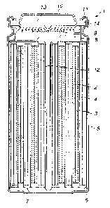
Fig. I is a longitudinal cross-sectional view showing an illustrative
structure of
anon-aqueous electrolyte cell according to the present invention.
Fig.2 shows charging curves of cells of samples I to 5.
Fig.3 shows discharging curves of cells of samples 1 to 5.
Fig.4 shows the relation between the volume upkeep ratio and the proportion
of the first lithium compound LiFePO4 for the samples 1 to 5 of the cells.
Fig.5 shows discharging curves of cells of samples 6 to 10.
Fig.6 shows the relation between the charging/discharging cycle and the volume
upkeep ratio of the samples 6 to 10.
Fig.7 shows discharging curves of cells of samples 11 to 16.
Fig.8 shows the relation between the charging/discharging cycle and the volume
upkeep ratio of the samples 11 to 16.
Fig.9 shows discharging curves for cells of samples 17 to 22.
Fig.10 shows the relation between the charging/discharging cycle and the
volume upkeep ratio of cells of the samples 17 to 22.
Fig. 11 shows an X-ray diffraction pattern of a first lithium compound
6
CA 02344981 2009-09-10
Li(Feo.4Mno.6)P04 as a first lithium compound synthesized in sample 23.
Fig. 12 shows a charging/discharging curve of a cell of sample 23.
Fig. 13 shows charging/discharging curves of cells of samples 23 and
24.DESCRIPTION OF THE PREFERRED EMBODIMENTS
The present invention is now explained with reference to certain preferred
embodiments thereof.
Fig. 1 is a longitudinal cross-sectional view showing an illustrative
structure
of a non-aqueous electrolyte cell according to the present invention. This non-
aqueous electrolyte cell 1 includes a coiled product, comprised of a strip-
like
positive electrode 2, a strip-like negative electrode 3, coiled in tight
contact with
each other with a separator 4 in-between, with the resulting coiled product
being
loaded in a cell can 5.
The positive electrode 2 is prepared by coating a positive electrode
mixture, containing a positive electrode active material and a binder, on a
current
collector and drying the so-coated mixture in situ. The current collector may,
for
example, be a metal foil, such as an aluminum foil.
The non-aqueous electrolyte cell 1 of the present invention uses, as a
positive electrode active material, a compound mass of a first lithium
compound
and a second lithium compound. The first lithium compound, represented by the
general formula LixMyPO4, where x is such that 0 <x< 2, y is such that 0.8 <y<
1.2 and M includes Fe, has a potential nobler than 3.45 which is the oxidation
potential of copper used extensively for a negative electrode current
collector,
whilst the second lithium compound is comprised mainly of known LiCoO2,
7
CA 02344981 2009-09-10
LiNiO2 or LiMn2O4 and has a potential nobler than 3.45V. The first lithium
compound may preferably be LiFePO4 or LiFeMnl_,PO4 where 0<z< 1, only by
way of examples.
By constructing the positive electrode active material by the first lithium
compound, having a potential nobler than 3.45V, and the second lithium
compound, having a potential nobler than 3.45V, lithium is extracted during
charging from the first lithium compound in the vicinity of 3.4V and
subsequently lithium is extracted from the second lithium compound in the
vicinity of 3.4 to 4.2V.
By constructing the positive electrode active material from the first lithium
compound having the potential nobler than 3.45 V which is the oxidation
potential of copper widely used for the negative electrode current collector,
and
from the second lithium compound having the potential nobler than 3.45V,
lithium is undoped from both the first and second lithium compounds so as to
be furnished to the negative electrode. So, with this non-aqueous electrolyte
cell
1, the amount of lithium doped to the negative electrode is the sun of the
lithium
capacities of the first and second lithium compounds.
Conversely, during discharging, the second lithium compound in the
positive electrode dopes lithium by way of discharging in the vicinity of 4.2
to 3.4
V. Then, at 3.4V and lower, the first lithium compound dopes lithium by way of
discharging.
So, the amount of lithium of the negative electrode is not depleted even
when the second lithium compound has discharged substantially completely. The
8
CA 02344981 2009-09-10
first lithium compound then is discharged. Since the potential of the first
lithium
compound is nobler at this tune than the oxidation potential of the negative
electrode current collector, the negative electrode current collector itself
does not
act like a negative electrode active material. So, the negative electrode
current
collector does not constitute a cell between it and the positive electrode
active
material, so that there is no risk of dissolution of the negative electrode
current
collector.
In the non-aqueous electrolyte cell 1 of the present invention, since the
potential generated by the first lithium compound during charging/discharging
as
described above is close to that generated by the second lithium compound,
discontinuous voltage changes during charging/discharging can be suppressed to
a minimum even if the electrode is a composite electrode composed of the first
and second lithium compounds thus realizing a smooth charging/discharging
curve. Moreover, a charging/discharging curve similar in profile to one for
the
case of using the first positive electrode active material alone may be
realized.
Thus, the non-aqueous electrolyte cell 1 may be operated in substantially
the same voltage range as when the second lithium compound, that is the
lithium
compound, such as LiCoO2, LiNiO2 or LiMn2O4 routinely used as the
positive electrode active material, is used alone, thus achieving the
compatibility. Moreover, the lithium compound, essentially based on
LiFePO4 more stable chemically and less costly than the conventional
lithium compound, is compounded, thus allowing to construct a cell
system appreciably improved in stability and cost. Specifically, the
9
CA 02344981 2001-04-25
non-aqueous electrolyte cell 1 of the present invention is superior in
charging/discharging characteristics and in cyclic characteristics.
In addition, since the potential generated by the first lithium compound and
the
potential generated by the second lithium compound are close to each other,
with the
copper oxidation potential of 3.45 V in-between, discontinuous voltage changes
during
the charging/discharging, otherwise caused by using the compounded electrode
of the
first and second lithium compounds, may be suppressed to a minimum to achieve
a
smooth charging/discharging curve. Moreover, according to the present
invention,
since the energy density of the first lithium compound LiFePO4 and that of the
second
lithium compound comprised basically of routinely used LiCoO2, LiNiO2 and
LiMn2O4, the aforementioned various added values can be afforded as the high
energy
density in a sum total is maintained.
Moreover, in the present non-aqueous electrolyte cell 1, there may be mixed a
compound(s) other than the aforementioned first and second lithium compounds,
in
order to constitute the positive electrode active material.
As the binder of the positive electrode active material, any suitable known
binder(s) routinely used for the positive electrode mixture of the cell may be
used. In
addition, any suitable known additive(s), such as electrification agent(s),
maybe added
to the positive electrode mixture.
The negative electrode 3 is prepared by coating a negative electrode mixture,
containing a negative electrode active material capable of doping/undoping
lithium,
CA 02344981 2001-04-25
and a binder, on the negative electrode current collector, and drying the
negative
electrode mixture thus coated in situ. As the negative electrode current
collector, a foil
of metal that cannot be alloyed with lithium may be used. In particular, a
copper foil
or a nickel foil is preferred. Also, a metal foil plated with copper or nickel
may be
used.
As the negative electrode active material, a carbonaceous material or an alloy
mmaterial; not containing lithium and having a large capacity for lithium (the
potential
.lithium doping quantity) is used. As the carbonaceous material, carbon
materials, such
as pyrocarbons, cokes, graphites, vitreous carbon fibers, sintered organic
high
molecular compounds, carbon fibers or activated charcoal, capable of
doping/undoping
lithium, may be used. The cokes may be exemplified by pitch coke, needle coke
and
petroleum coke. The sintered organic high molecular compounds mean phenolic or
furan resins carbonified on firing at a suitable temperature.
The aforementioned alloy :material means a compound represented by the
chemical formula M.M'Liz where M is a metal element that can be alloyed with
lithium, M' is an element Li and one or more metal element other than the
element M,
x is a number larger than 0, and y, z are numbers not less than 0. The
semiconductor
elements, namely B, Si and As, are also comprehended in the metal element.
Examples of the alloy materials include metals, such as Mg, B, Al, Ga, In, Si,
Sri, Pb,
Sb, Bi, Cd, Ag, Zn, Hf, Zr, and Y, alloys thereof, Li-Al, Li-Al-M, M being one
or more
of the group 2A, 3B or 4B transition metal elements, AISb, and CuMgSb.
11
CA 02344981 2001-04-25
As the elements that can be alloyed with lithium, preferably typical elements
of
the group 3B, more preferably Si or Sri, and most preferably Si, may be used.
More
specifically, compounds represented by M,Si or M,;Mn, where M denotes one or
more
metal element excluding Si or Sn,, are used. Specified examples of the
elements
include S1134, SiB6, Mg2Si, Mg2Sn, Ni2Si, TiSi2, MoSi2, CoSi2, NiSi2, CaSi2,
CrSi2,
('u5Si FeSi2, MnSi2, NbSi2, TaSi2, )JSi2, WSi2, and ZnSi2.
Moreover, metal elements other than the group 4B elements, including one or
more non-metallic elements, and excluding carbon, may be contained in the
negative
electrode active material. Examples of these negative electrode active
materials
include SiC, Si3N4, Si2N2O, Ge2N2O, SiO,;, where 0 <xs 2, SnOx, where 0 <x_<
2, SnO,;,
where 0 <x_< 2, LiSiO and LiSnO.
Although there is no limitation to the method for the preparation of the
negative
electrode active material, a mechanical ironing method, or a method of mixing
starting
compounds and heating the resulting mixture in an inert atmosphere or a in
reducing
atmosphere, may be used. Two or more of the above-mentioned materials may be
mixed in the negative electrode active material. These materials may be doped
electro-
chemically within the cell following the preparation of the cell.
Alternatively, lithium
may be supplied following or prior to cell preparation from a positive
electrode or
from a lithium source other than the positive electrode. The negative
electrode active
material may also be synthesized as the lithium containing material during
synthesis
of the material so as to be contained in the negative electrode during
preparation of the
12
CA 02344981 2001-04-25
cell.
As the binder contained in the layer of the negative electrode active
material,
any suitable resin material, routinely used as a binder of the layer of the
negative
electrode active material of this sort of the non-aqueous electrolyte cell,
may be used.
A foil of metal lithium, which proves a negative electrode active material,
may also be
used as a negative electrode active material.
. The separator 4 is arranged between the positive electrode 2 and the
negative
electrode 3 to prevent shorting due to physical contact across the positive
electrode 2.
and the negative electrode 3. The separator 4 may be formed of any suitable
known
material routinely used for a separator of this sort of the non-aqueous
electrolyte cell,
such as a high-molecular film of e.g., polypropylene. The separator is
preferably as
thin in thickness as possible in view of the lithium ion conductivity and the
energy
density. For example, the separator is desirably not larger than 50 [tin.
As the non-aqueous electrolytic solution, such a solution of an electrolyte
dissolved in a non-protonic non-aqueous solvent may be used
As the non-aqueous solvent, propylene carbonate, ethylene carbonate, butylene
carbonate, vinylene carbonate, y-butyl lactone, sulfolane, methyl sulfolane,
1, 2-
dimethoxyethane, 1,2-diethoxyethane, tetrahydrofuran, 2-methyl
tetrahydrofuran, 1,
3-dioxorane, 4-methyl 1, 3-dioxorane, methyl propionate, methyl butyrate,
dimethyl
carbonate, diethyl carbonate, dipropyl carbonate, diethylether, acetonitrile,
propionitrile, anisole, acetic acid esters, lactic acid esters, and propionic
acid esters,
13
CA 02344981 2001-04-25
may be used. In particular, cyclic carbonates, such as propylene carbonate or
vinylene
carbonate, or chained carbonates, such as dimethyl carbonate, diethyl
carbonate,
dipropyl carbonate, may be used in view of voltage stability. These non-
aqueous
solvents may be used alone or as a mixture.
As the electrolyte, dissolved in the non-aqueous solvent, lithium salts, such
as
LiCl, LiBr, LiPF6, LiC1O4, LiAsF,;, LiBF4, LiCH3SO3, LiCF3SO3, LiN(CF3SO2)2 or
LiB(C6HS)4, may be used. Of these lithium salts, LIPF6 and LiBF4 are most
preferred.
In the non-aqueous electrolyte cell 1 according to the present invention, as
described above, containing a compound system of the first and second lithium
compounds, as the positive electrode active material, charging occurs in
stability, while
the over-discharging state may be suppressed to assure superior
charging/discharging
characteristics and cyclic characteristics.
The non-aqueous electrolyte cell 1, employing the compound system ofthe first
and second lithium compounds, as the positive electrode active material, may,
for
example, be prepared in the following manner:
The positive electrode 2 is prepared by coating a positive electrode mixture,
containing the positive electrode active material and the binder, on a metal
foil, such
as an aluminum foil, operating as a positive electrode current collector, and
drying the
entire assembly in situ to form the layer of the positive electrode active
material. As
the binder of the positive electrode mixture, any suitable known binder may be
used.
In addition, any suitable known additive may be added to the positive
electrode
14
CA 02344981 2001-04-25
mixture.
The negative electrode 3 may be prepared by uniformly coating the negative
electrode mixture, containing the negative electrode active material and the
binder, on
a metal foil, such as copper foil, acting as a negative electrode current
collector, and
drying the assembly in situ to form a layer of the negative electrode active
material.
As the binder of the negative electrode mixture, any suitable known binder may
be
used. In addition, any suitable known additive may be added to the negative
electrode
mixture.
The positive electrode 2 and the negative electrode 3, obtained as described
above, are tightly affixed together., with e.g., the separator 4 of a micro-
porous
polypropylene film in-between, with the resulting assembly being coiled
spirally a
number of times to form a coiled member.
The insulating plate 6 then is inserted on the bottom of an iron cell can 5,
the
inner surface of which is plated with nickel, and the coiled member is placed
thereon.
For current collection of the negative electrode, one end of a negative
electrode lead
7, fonned e.g., of nickel, is press-fitted to the negative electrode 3, with
its other end
being welded to the cell can 5. This electrically connects the cell can 5 to
the negative
electrode 3 so that the cell can 5 serves as an external negative electrode of
the non-
aqueous electrolyte cell 1. Also, for current collection of the positive
electrode, one
end of a positive electrode lead 8, formed e.g., of aluminum, is mounted on
the
positive electrode 2, with its other end being electrically connected to a
cell lid 10
CA 02344981 2001-04-25
through a thin sheet for current interruption 9. This thin sheet for current
interruption
9 breaks the current responsive to the internal pressure of the cell. This
electrically
connects the cell lid 10 to the positive electrode 2 so that the cell lid 10
serves as an
external positive electrode of the non-aqueous electrolyte cell 1.
The inside of the cell can 5 then is charged with the non-aqueous electrolytic
solution which is prepared by dissolving the electrolyte in the non-aqueous
solvent.
The cell can 5 then is caulked through an insulating sealing gasket 11, coated
with asphalt, to secure the cell lid 10 to complete the cylindrically-shaped
non-aqueous
electrolyte cell 1.
This non-aqueous electrolyte cell I is provided with a center pin 12,
connected
to the negative electrode lead 7 and to the positive electrode lead 8, a
safetyvalve
device 13 for exhausting the inner gas when the pressure in the cell is higher
than a
pre-set value, and with a PTC device 14 for preventing the temperature in the
cell from.
increasing, as shown in Fig. 1.
Although the foregoing description has been made of the non-aqueous
electrolyte cell 1, employing the non-aqueous electrolytic solution as the non-
aqueous
electrolyte cell, as an example, the non-aqueous electrolyte cell pertaining
to the
present invention is not limited to the above-described structure. For
example, the
present invention can be applied to the case of using the solid electrolyte or
a gelated
electrolyte containing a swelling solvent as the non-aqueous electrolyte.
The solid electrolyte used may be any of an inorganic solid electrolyte and a
16
CA 02344981 2001-04-25
high molecular solid electrolyte, provided that the electrolyte is formed of a
material
exhibiting lithium ion conductivity. The inorganic solid electrolyte may be
lithium
nitride or lithium iodide. The high molecular solid electrolyte is composed of
an
electrolyte salt and a high molecular compound in which the electrolyte salt
is
dispersed. The high molecular solid electrolyte may be an etheric high
molecular
material, such as poly(ethylene oxide), cross-linked or not, a
poly(methacrylate) ester
based high molecular material or an acrylate-based high molecular material.
The high
molecular solid electrolyte may be used alone or as a copolyrner or mixture.
The matrix used for a gellated solid electrolyte may be a variety of high
molecular materials provided that the matrix is able to absorb and gelate the
non-
aqueous electrolytic solution. For example, fluorine-based high molecular
materials,
such as poly(vinylidene fluoride) or poly(vinylidene fluoride -co-
hexafluoropropylene), etheric high molecular materials, such as poly(ethylene
oxide),
cross-linked or not, or poly(acrylonitrile), may be used. In particular,
fluorine-based
high molecular materials are preferably used in view of redox stability.
Although a secondary cell is taken as an example in the above-described
embodiment, the present invention is not limited thereto, since it may also be
applied
to a primary cell. The cell of the present invention is not limited as to its
shape, such
that it may be cylindrical, square-shaped, coin-shaped or button-shaped.
Moreover,
it may be of any desired size, such that it may be of a thin type or a large-
sized.
Examples
17
CA 02344981 2001-04-25
The present invention is hereinafter explained with reference to certain
numerical examples intended for checking upon its effect. The present
invention is,
of course, not limited to these Examples.
First, samples of coin-shaped non-aqueous electrolytic solution secondary
cells
were prepared, as samples 1 to 5., using a mixture of the first lithium
compound
LiFePO4 and the second lithium compound LiCoO2, as a positive electrode active
material, to check upon characteristics thereof.
<Sample 1>
First, the positive electrode active material was prepared as follows:
LiFePO4, as the first lithium compound, was synthesized as follows: Iron
acetate Fe(CH3CO2)2, anunonium phosphate NH4H2PO4 and lithium carbonate Li2CO3
were mixed sufficiently to a molar ratio of 2:2:1. The resulting mixture was
directly
calcined in a nitrogen atmosphere at 300 C for 12 hours, and fired at 600 C
for 24
hours in a nitrogen atmosphere. By X-ray diffraction analyses; the produced
powders
were identified to be the single-phase L]FePO4.
Then, LiFePO4 produced and LiCoO2 as the second lithium compound were
mixed together at a weight ratio of 10:90 to give a mixture which then was
used as a
positive electrode active material.
Using the so-produced positive electrode active material, the positive
electrode
was prepared as now explained and, using the positive electrode, so prepared,
a coin-
type non-aqueous electrolytic solution secondary cell was prepared.
18
CA 02344981 2001-04-25
70 wt% of the dried positive electrode active material, 25 wt% of acetylene
black, as an electrification agent, and 5 wt% of PVDF (Aldrich # 1300), as a
binder,
were kneaded together, using DMF, to prepare a paste-like positive electrode
mixture.
This positive electrode mixture was coated on an aluminum mesh, operating as a
positive electrode current collector, and the resulting assembly was
compression-
molded and dried at 100 C for one hour in a dry argon stream to form a
positive
electrode pellet. Meanwhile, 60 nig of the positive electrode active material
was
carried by each positive electrode pellet.
A positive electrode pellet was accommodated in a positive electrode can,
whilst
lithium metal was accommodated in a negative electrode can. A separator was
arranged between the negative and positive electrodes and a non-aqueous
electrolytic
solution was poured into the negative and positive electrode cans. The non-
aqueous
electrolytic solution was prepared by dissolving LiPF66in a solvent mixture
comprised
of equal volumes of propylene carbonate and dimethyl carbonate in a
concentration
of 1 mol/l.
Finally, the negative and positive electrode cans were caulked and secured
together through an insulating gasket to complete a 2025 coin-shaped non-
aqueous
electrolyte secondary cell.
<Sample 2>
A positive electrode was prepared in the same way as in sample 1 except
changing the weight ratio of the first lithium compound LiFePO4 to the second
lithium
19
CA 02344981 2001-04-25
compound LiCoO2 to 20:80 in producing the positive electrode active material.
Using
this positive electrode active material, a coin-shaped non-aqueous
electrolytic solution
secondary cell was produced.
<Sample 3>
A positive electrode was prepared in the same way as in sample 1 except
changing the weight ratio of the first lithium compound LiFePO4 to the second
lithium
compound LiCoO2 to 30:70 in producing the positive electrode active material.
Using
this positive electrode active material, a coin-shaped non-aqueous
electrolytic solution
secondary cell was produced.
<Sample 4>
A positive electrode was prepared in the same way as in sample 1 except
changing the weight ratio of the first lithium compound LiFePO4 to the second
lithium
compound LiCoO2 to 40:60 in producing the positive electrode active material.
Using
this positive electrode active material, a coin-shaped non-aqueous
electrolytic solution
secondary cell was produced.
<Sainple 5>
A positive electrode was prepared in the same way as in sample 1 except
changing the weight ratio of the first lithium compound LiFePO4 to the second
lithium
compound LiCoO2 to 50:50 in producing the positive electrode active material.
Using
this positive electrode active material, a coin-shaped non-aqueous
electrolytic solution
secondary cell was produced.
CA 02344981 2001-04-25
A charging/discharging test was carried out on the samples 1 to 5 of the non-
aqueous electrolytic solution secondary cell, prepared as described above.
The constant current charging was carried out up to 4.2V, which voltage was
kept in carrying out the charging. The charging was tenninated when the
current was
below 0.01 mA/cm2. The discharging then was carried out and was terminated
when
the voltage fell to 2.0 V. For both charging and discharging, the ambient
temperature
(23 C) was used, and the current density was set to 0.12 mA/cm2.
The charging curves for the samples I to 5 are shown in Figs.2 and the
discharging curves for the same samples are shown in Fig.3.
It is seen from Fig.2 that a two-step shoulder appears in each charging curve,
from which it is seen that, during charging, lithium is first extracted from
the first
lithium compound LiFePO4 in an area in the vicinity of 3.8 to 4.2V and then
extracted
from the second lithium compound LiCoO2 in an area in the vicinity of 3.8 to
4.2V.
It is likewise seen from Fig.3 that a two-step shoulder appears in each
discharging curve, from which it is seen that, during discharging, the second
lithium
compound LiCoO2 is discharged as it dopes lithium in an area in the vicinity
of 3.8 to
4.2V and then the first lithium compound LiFePO4 is discharged as it dopes
lithium in
the vicinity of 3.4V.
It is also seen from Figs.2 and. 3 that, as the LiFePO4 mixing ratio is
increased,
the average voltage is slightly lowered, whilst the capacity is increased
gradually.
The cells of the samples 1 to 5 were further charged to 4.2V and allowed to
21
CA 02344981 2001-04-25
S. R
stand for one hour in an environment of 60 C. The discharging then was carried
out
to find the volume upkeep ratio, that is the ratio (%) of the capacity of the
samples
prior to allowing them to stand to that of the samples subsequent to allowing
them to
stand.
Fig.4 shows the results thus found in comparison with the proportion of the
first
lithium compound LiFePO4 in the positive electrode active material. It is seen
from
Fig.4 that, as the proportion of LiF'ePO4 is increased, the volumetric upkeep
ratio is
improved, such that the high-temperature storage deterioration is suppressed
appreciably.
Using a mixture of the second lithium compound LiFePO4 and the second
lithium compound LiNi0.8Co0.202 as the positive electrode active material,
samples of
the coin-shaped non-aqueous electrolytic solution secondary cells were
prepared as
samples 6 to 10 to check upon characteristics thereof.
<Sample 6>
A positive electrode was prepared in the same way as in sample 1, except that
LiNi0.8Co0.2O2 was used as the second lithium compound in place of LiCoO2 and
that
the first lithium compound LiFePO4 , and the second lithium compound
LiMn0.8Mg0.2O2
were mixed at a weight ratio of 10:90 so as to be used as the positive
electrode active
material. Using this positive electrode, a coin-shaped non-aqueous
electrolytic
solution secondary cell was prepared.
<Sample 7>
22
CA 02344981 2001-04-25
A positive electrode was prepared in the same way as the sample 6, except
changing the weight ratio of the first lithium compound LiFePO4 and the second
lithium compound LiMna8Mg0.2O2 to 20:80. Using the positive electrode active
material, so prepared, a coin-shaped non-aqueous electrolytic solution
secondary cell
was prepared.
<Sample 8>
A positive electrode was prepared in the same way as the sample 6, except
changing the weight ratio of the first lithium compound LiFePO4 and the second
lithium compound LiMn0.8Mg0.2O2 to 30:70. Using the positive electrode active
material, so prepared, a coin-shaped non-aqueous electrolytic solution
secondary cell
was prepared.
<Sample 9>
A positive electrode was prepared in the same way as the sample 6, except
changing the weight ratio of the first lithium compound LiFePO4 and the second
lithium compound LiMn0.8Mg0.2O2 to 40:60. Using the positive electrode active
material, so prepared, a coin-shaped non-aqueous electrolytic solution
secondary cell
was prepared.
<Sample 10>
A positive electrode was prepared in the same way as the sample 6, except
changing the weight ratio of the first lithium compound LiFePO4 and the second
lithium compound LiMn0.8Mg0.2O2 to 50:50. Using the positive electrode active
23
CA 02344981 2001-04-25
material, so prepared, a coin-shaped non-aqueous electrolytic solution
secondary cell
was prepared.
A charging/discharging test was carried out on the non-aqueous electrolytic
Solution secondary cells of the samples 6 to 10, prepared as described above,
under the
same conditions as described above. Fig.5 shows a corresponding discharge
curve.
It is seen from Fig.5 that, during discharging, the second lithium compound
LiMno.8Mg0.2O2 is discharged in an area in the vicinity of 3.5 to 4.2V, as it
dopes
lithium, with the first lithium compound LiFePO4 being then discharged in the
vicinity
of 3.4V, as it dopes lithium. Since the operating voltages of the two
compounds are
close to each other, a smooth discharging curve is realized.
Of the non-aqueous electrolytic solution secondary cells of the samples 6 to
10,
measurements were made of repetitive charging/discharging characteristics in
the
voltage range of 4.2 to 2.OV. The results are shown in Fig.6, from which it is
seen
that, as the mixing ratio of the first lithium compound LiFePO4 is increased,
the cyclic
characteristics are improved appreciably.
Using a mixture of the first lithium compound LiFePO4 and the second lithium
compound LiCoO2 as the positive electrode active material, samples of the
cylindrically-shaped non-aqueous electrolytic solution secondary cells were
prepared
to check upon characteristics thereof.
<Sample 11>
First, a positive electrode was prepared as follows:
24
CA 02344981 2001-04-25
The first lithium compound Lit=ePO4 and the second lithium compound LiCoO2
were mixed at a ratio of 10:90 to give a positive electrode active material.
91 parts by weight of the positive electrode active material, 6 parts by
weight
of graphite, as an electrification agent and 3 parts by weight
ofpolyvinylidene fluoride,
as a binder, were mixed together. 100 parts by weight of N-methyl pyrrolidone
as a
solvent were mixed to the resulting mixture to form a slurried mixture.
This positive electrode mixture was evenly coated on both surfaces of a strip-
shaped aluminum foil, 20 m in thickness, operating as a positive electrode
current
collector. The resulting product was dried and compression-molded by a roll
press to
form a strip-shaped positive electrode. In this strip-shaped positive
electrode, the layer
of the positive electrode active material was formed to substantially the same
thickness
on each surface of the positive electrode current collector.
The negative electrode was prepared as follows:
90 parts by weight of pulverized graphite as a negative electrode active
material,
and 10 parts by weight of polyvinylidene fluoride, as a binder, were mixed
together.
To the resulting mixture were added 100 parts by weight of N-methyl
pyrrolidone, as
a solvent, to form a slurried negative electrode mixture.
This negative electrode mixture was evenly coated on both surfaces of a strip-
shaped copper foil, 10 [a.m in thickness, operating as a negative electrode
current
collector. The resulting product was dried and compression-molded by a roll
press to
fonn a strip-shaped positive electrode. In this strip-shaped positive
electrode, the layer
CA 02344981 2001-04-25
of the negative electrode active material was formed to substantially the same
thickness on each surface of the negative electrode current collector.
The positive electrode, negative electrode and a pair of separators were
layered
together and coiled a number of times to form a coiled product. Specifically,
the strip-
shaped positive electrode, separators and the strip-shaped positive electrode
were
layered together in this order and the resulting layered product was coiled a
number
of times to give a hollow rod to form the coiled product.
An insulating plate then was inserted on the bottom of an iron cell can, the
inner
surface of which is plated with nickel, and the coiled product is placed
thereon. For
current collection of the negative electrode, one end of a negative electrode
lead 7,
formed e.g., of nickel, is press-fitted to the negative electrode 3, with its
other end
being welded to the cell can 5. For current collection of the positive
electrode, one end
of a positive electrode lead, formed e.g., of aluminum, was mounted on the
positive
electrode 2, with its other end being electrically connected to a cell lid 10
through a
thin sheet used for current interruption. The inside of the cell can 5-then
was charged
with the non-aqueous electrolytic solution which was prepared at the outset by
dissolving LiPF6in a solvent mixture of equal volumes of propylene carbonate
and 1,
2-dimethoxyethane at a concentration of 1 mol/l.
The cell can 5 then was caulked through an insulating sealing gasket, coated
with asphalt, to secure the cell lid to complete the cylindrically-shaped non-
aqueous
electrolyte cell 1 having an outer size of 20.5 min and a height of 42 mm.
26
CA 02344981 2001-04-25
<Sample 12>
A positive electrode was prepared in the same way as sample 1, except changing
the weight ratio of the first lithium compound LiFePO4 and the second lithium
compound LiCoO2 in producing the positive electrode active material to 20:80
and,
using this positive electrode, a cylindrically-shaped non-aqueous electrolyte
cell was
prepared.
-,Sample 13>
A positive electrode was prepared in the same way as sample 1, except changing
the weight ratio of the first lithium compound LiFePO4 and the second lithium
compound LiCoO2 in producing the positive electrode active material to 30:70
and,
.using this positive electrode, a cylindrically-shaped non-aqueous electrolyte
cell was
prepared.
<Sample 14>
A positive electrode was prepared in the same way as sample 1, except changing
the weight ratio of the first lithium compound LiFePO4 and the second lithium
compound LiCoO2 in producing the positive electrode active material to 40:60
and,
.using this positive electrode, a cylindrically-shaped non-aqueous electrolyte
cell was
prepared.
<Sample 15>
A positive electrode was prepared in the same way as sample 1, except changing
the weight ratio of the first lithium compound LiFePO4 and the second lithium
27
CA 02344981 2001-04-25
compound LiCoO2 in producing the positive electrode active material to 50:50
and,
using this positive electrode, a cylindrically-shaped non-aqueous electrolyte
cell was
prepared.
<Sample 16>
A positive electrode was prepared in the same way as in sample l except using
only the second lithium compound LiCoO2 in producing the positive electrode
active
material and, using this positive electrode, a cylindrically-shaped non-
aqueous
electrolyte cell was prepared.
The non-aqueous electrolytic solution secondary cells of the samples 11 to 16,
prepared as described above, were charged to 4.1 V, at the constant current of
200 mA,
and discharged to OV with a load of 7.50. Fig.7 shows a corresponding
discharging
curve.
It is seen from Fig.7 that the sample 11 of the non-aqueous electrolytic
solution
secondary cell, with the amount of addition of the first lithium compound
LiFePO4 of
wt%, has a discharging curve substantially analogous to one of the sample 16
of the
non-aqueous electrolytic solution secondary cell employing only the second
lithium
compound LiCoO2. However, if the amount of addition of the first lithium
compound
exceeds 20 wt%, a shoulder tends to be observed towards the end of the
discharging
period. It is also seen that the cell voltage of the totality of the non-
aqueous
electrolytic solution secondary cells becomes approximately equal to zero in
about
four hours thus indicating the state of overcharging.
28
CA 02344981 2001-04-25
The samples 11 to 16 of the non-aqueous electrolytic solution secondary cells
were dismantled and checked. It was found that dissolution of the negative
electrode
current collector was observed in none of the samples 11 to 15 of the non-
aqueous
electrolytic solution secondary cells. On the other hand, part of the copper
current
collector was dissolved in the sample 16 of the non-aqueous electrolytic
solution
secondary cell employing only LiCoO2 for the positive electrode, such that
pits were
formed in the copper current collector.
Moreover, the samples 11 to 16 of the non-aqueous electrolytic solution
secondary cells were put to a cyclic test of charging the cells, and over-
discharging the
cells to OV, under the same charging/discharging conditions as those of Fig.7,
and
allowing the cells to stand for 24 hours, in a repetitive fashion. Fig.8 shows
the
relation between the number of cycles and the discharge capacity upkeep ratio
relative
to the initial capacity.
As may be seen from Fig.8, the sample 16 of the non-aqueous electrolytic
solution secondary cell, employing only LiCoO2 for the positive electrode, the
capacity
is decreased precipitously, while the samples 11 to 16 of the non-aqueous
electrolytic
solution secondary cells maintained the capacity not less than 60% even after
cycling
five or more times. Since it is presumably only a rare occurrence that a cell
mounted
on a real equipment be over-discharged and kept at OV for prolonged time, no
practical
inconvenience possibly is produced on the condition that the capacity of this
order of
magnitude is maintained.
29
CA 02344981 2001-04-25
In samples 17 to 22, cylindrically-shaped non-aqueous electrolytic solution
secondary cells were prepared, using a mixture of the first lithium compound
LiFePO4
and the second lithium compound LiNi008Co0_202 as a positive electrode active
material,
to check for cell characteristics.
<Sample 17>
A positive electrode was prepared in the same way as in sample 11, except
using
LiNi0.8Co0.2O2 in place ofLiCoO2 as the second lithium compound, and mixing
the first
lithium compound LiFePO4 and the second lithium compound LiNi0.8Co0.2O2 at a
weight ratio of 10:90 to form the positive electrode active material. A
cylindrically-
shaped non-aqueous electrolytic solution secondary cell was prepared using the
so-
prepared positive electrode.
<Sample 18>
A positive electrode was prepared in the same way as in sample 17, except
changing the weight ratio of the first lithium compound LiFePO4 and the second
lithium compound LiNi0`8Co0.2O2 to 20:80, in producing the positive electrode
active
material, and a cylindrically-shaped non-aqueous electrolytic solution
secondary cell
was prepared using this positive electrode.
<Sample 19>
A positive electrode was prepared in the same way as in sample 17, except
changing the weight ratio of the first lithium compound LiFePO4 and the second
lithium compound LiNi0.8Co0_202 to 30:70, in producing the positive electrode
active
CA 02344981 2001-04-25
material, and a cylindrically-shaped non-aqueous electrolytic solution
secondary cell
was prepared using this positive electrode.
<Sample 20>
A positive electrode was prepared in the same way as in sample 17, except
changing the weight ratio of the first lithium compound LiFePO4 and the second
lithium compound LiNi0.8Co0.2O2 to 40:60, in producing the positive electrode
active
material, and a cylindrically-shaped non-aqueous electrolytic solution
secondary cell
was prepared using this positive electrode.
<--Sample 21>
A positive electrode was prepared in the same way as in sample 17, except
changing the weight ratio of the first lithium compound LiFePO4 and the second
lithium compound LiNi0.8Co022O2 to 50:50, in producing the positive electrode
active
material, and a cylindrically-shaped non-aqueous electrolytic solution
secondary cell
was prepared using this positive electrode.
<Sample 22>
A positive electrode was prepared in the same way as in sample 17 except using
only the second lithium compound LiNi0.8Co0.2O2, in producing the positive
electrode
active material and, using this positive electrode, a cylindrically-shaped non-
aqueous
electrolyte cell was prepared.
The samples 17 to 22 of the non-aqueous electrolytic solution secondary cells,
prepared as described above, were charged to 4.1 V, at the constant current of
200 mA,
31
CA 02344981 2001-04-25
and subsequently discharged to OV under a load of 7.50. Fig.9 shows a
corresponding
discharging curve.
It is seen from Fig.9 that the sample 17 of the non-aqueous electrolytic
solution
secondary cell with the amount of addition of the first lithium compound
LiFePO4
equal to 10 wt% shows a discharging curve similar to one of the sample 22 of
the non-
aqueous electrolytic solution secondary cell employing only the second lithium
compound LiNio 8Co0.2O2. However, if the amount of addition of the first
lithium
compound exceeds 20 wt%, a shoulder becomes noticeable towards the end of the
discharging period. It is also seen that the cell voltage of each of the non-
aqueous
electrolytic solution secondary cells is substantially OV in four hours thus
demonstrating the over-discharging state.
The samples 17 to 22 of the non-aqueous electrolytic solution secondary cells
were dismantled and checked. It was found that dissolution of the negative
electrode
current collector was observed in none of the samples 17 to 21 of the non-
aqueous
electrolytic solution secondary cells. On the other hand, part of the copper
current
collector was dissolved in the sample 22 of the non-aqueous electrolytic
solution
secondary cell employing only LiN 0.8Co0 2O2 for the positive electrode, such
that pits
were formed in the copper current collector.
Moreover, the samples 17 to 22 of the non-aqueous electrolytic solution
secondary cells were put to a cyclic test of charging the cells, and over-
discharging the
cells to OV, under the same charging/discharging conditions as those of Fig.9,
and
32
CA 02344981 2001-04-25
allowing the cells to stand for 24 hours, in a repetitive fashion. Fig. 10
shows the
relation between the number of cycles and the discharge capacity upkeep ratio
relative
to the initial capacity.
As may be seen from Fig. 10, the sample 22 of the non-aqueous electrolytic
solution secondary cell, employing only LiNi0.8Co0.2O2 for the positive
electrode, the
capacity is decreased precipitously, while the samples 11 to 22 of the non-
aqueous
electrolytic solution secondary cells maintained the capacity not less than
70% even
after cycling five or more times. Since it is presumably only a rare
occurrence that a
cell mounted on a real equipment be over-discharged and kept at OV for
prolonged
time, no practical inconvenience possibly is produced on the condition that
the
capacity of this order of magnitude is maintained.
In samples 23 and 24, coin-shaped non-aqueous electrolytic solution secondary
cells were prepared, using a mixture of the first lithium compound Li(Fe0.4Mn0
6)PO4
and the second lithium, compound LiNiO.8Co0.2O2 as a positive electrode active
material,
to check for cell characteristics.
<Sample 23>
Li(Fe0.4Mn0.6)PO4, as the first lithium compound, was synthesized as follows:
'Iron acetate MgC2O4.2H2O, manganese carbonate MnCO3 and ammnonium phosphate
:NH4H2PO4 and lithium carbonate Li2CO3 were mixed sufficiently. The resulting
mixture was directly calcined in a nitrogen atmosphere at 300 C for 12 hours,
and
:fired at 600 C for 24 hours in a nitrogen atmosphere. X-ray diffraction
analyses of the
33
CA 02344981 2001-04-25
produced powders revealed that the single-phase Li(Fe044Mn0.G)PO4 has been
synthesized.
Then, Li(Fe0.4Mn0.C)PO4 produced and LiNiO.ICo022O2 as the second lithium
compound were mixed together at a weight ratio of 30:70 to give a mixture
which then
was used as a positive electrode active material.
Using the so-produced positive electrode active material, the positive
electrode
was prepared as now explained and, using the positive electrode, so prepared,
a coin-
type non-aqueous electrolytic solution secondary cell was prepared.
<Sample 24>
A positive electrode was prepared in the same way as in sample 23, except
using
only Li(Fe0.4Mn0.6)PO4, which is the first lithium compound, as the positive
electrode
active material. Using this positive electrode, a coin-shaped non-aqueous
electrolytic
solution secondary cell was prepared.
The samples 23, 24 of the non-aqueous electrolytic solution secondary cells ,
prepared as described above, were put to a charging/discharging test.
The charging was conducted at constant current up to 4.2V, which voltage then
was kept. The charging was terminated when the current fell to 0.01 mA/cm2 or
less.
The discharging was carried out subsequently and terminated when the voltage
fell to
2.OV. The charging and discharging were carried out at an ambient temperature
of
23 C. For both charging and discharging, the current density was 0.12 mA/cm2.
Fig. 12 shows charging/discharging characteristics of the sample 24 of the
coin-
34
CA 02344981 2001-04-25
S.
shaped non-aqueous electrolytic solution secondary cell employing only
Li(Fe0.4Mn0.6)PO4. From Fig. 12 may be confirmed not only the capacity
observed in
the 3.4 V area as seen in LiFePO4 but also the capacity in the vicinity of 4V.
Fig. 13 shows discharging characteristics of the samples 23, 24 of the coin-
shaped non-aqueous electrolytic solution secondary cells. It is seen from Fig.
13 that
LiNi0 8Co0.2O2 is in operation in an area in the vicinity of 3.5 to 4.2V,
while
Li(Fe0.4Mn0.6)PO4 is in operation in. the vicinity of 3.4 and 4.OV. Since the
operating
voltages of the two are close to each other, smooth charging/discharging
characteristics may be achieved. In addition, since there is a 4V potential in
Li(Fe0.4Mn0.6)PO4, the difference from the charging/discharging
characteristics proper
to LiNi0.8Co0.2O2 by itself is suppressed to a smaller value.
Moreover, the samples 23, 24 of the coin-shaped non-aqueous electrolytic
solution secondary cells were charged under the charging/discharging
conditions
similar to those of Fig. 12 and over-discharged to OV. The cells were allowed
to stand
in this state for 24 hours. This cycle of operations was carried out
repeatedly. It may
be seen from this cyclic test that, by using the compound electrode with
Li(Fe0.4Mn0.6)PO4, the cyclic characteristics are improved appreciably. It has
also
been confirmed that the non-aqueous electrolyte secondary cell of the sample
24
employing only Li(Fe044Mn0.6)PO4 as the positive electrode undergoes capacity
deterioration precipitously, whereas, in the non-aqueous electrolyte secondary
cell of
sample 23 employing the compound electrode with Li(Fe0.4Mn0.6)PO4, the cyclic
CA 02344981 2001-04-25
characteristics may be improved appreciably.
36