Note: Descriptions are shown in the official language in which they were submitted.
CA 02345160 2001-04-25
TITLE: MULTIFUNCTIONAL FLOWER POT
FIELD OF THE INVENTION
This invention relates to a multifunctional flower pot
system. In particular the present invention provides a
flower pot system primarily designed to rest on a patio
table encircling an umbrella pole but when the patio
table umbrella is not in place additional features are
provided to hold the flower pot on the table thus
preventing it from being inadvertently knocked or blown
off the table.
BACKGROUND OF THE INVENTION
Generally, patio tables may be found on patios or
terraces in many locales including residential backyards,
hotels, resorts and restaurants. The patio table may take
a number of shapes including rectangular, round and
square. By design the patio table provides for a hole in
its centre which allows for the pole of an umbrella to
protrude upward from its base; the umbrella awning
providing shade from the sun's rays or as decoration to
the area.
Unfortunately, the umbrella pole makes it very difficult
to place a floral centrepiece on the patio table.
Therefore it would be advantageous to have a flower pot
system or planter with a centre passageway which would
allow the pole to pass through. Further, it would be a
benefit if the flower pot system was able to be removed
and replaced for maintenance or for other reasons (e. g.
another type or flower or flower colour) without removing
the patio umbrella pole. The ease of removal and
replacement of the flower pot is important to avoid
spillage of the pot's contents in order to maintain the
cleanliness of the patio table as it is primarily
designed for the social interaction of individuals
consuming food and beverages. Further, the ease of
CA 02345160 2001-04-25
- 2 -
separation and joining is also a benefit when one
considers the weight of flower pots with earth or planter
mix and their awkwardness to grasp.
Existing prior art has identified the need to provide a
flower pot or planter which can be centred on a patio
table by encircling the pole when it is in place and also
the need to be able to separate and join the flower pot
halves without removing the umbrella pole.
U.S. Patent No. 5,960,587 shows a planter adapted for
circling an umbrella pole and resting upon a patio table
top. The planter includes a large pot divided into two
halves of identical geometry, and a drip tray similarly
divided into two halves of identical geometry. Features
are provided to lock each drip tray half into a
corresponding pot half. A dovetail system allows each pot
half to interlock to the another, thereby forming a
complete planter. The planter halves are separable by
lifting one half relative to the other to disengage the
dovetail interlock.
Numerous other patents describe a similar concept but
utilizing different shapes and methods of connection
including U.S. Patent Nos 1,499,473; 4,847,741;
4,597,221; 3,747,268; 5,967,359; 6,085,459; and U.S.
Design Patent Nos: Des 278,521; Des. 383,417; Des
393,816; Des 405,027; Des 409,520 and Des 416,214.
Although the prior art addresses and meets the basic
requirements to enable a flower pot comprised of two
separable halves to encircle an umbrella pole in the
centre of a patio table without removing the umbrella
pole, the art has not adequately addressed the
requirement for easy separation and joining given the
nature of the product. Specifically prior art showing a
flower pot comprised of two separable halves joined by
CA 02345160 2001-04-25
- 3 -
male/female interfaces or other means such as having to
place one piece inside another requires the user to have
the dexterity to be able to complete this function which
could be made very difficult by the weight and
awkwardness of the pots and the size of the male/female
interfaces being brought together. Further, depending on
the design of the joining mechanisms their function would
be rendered almost completely ineffective if any dirt or
debris interferes with them.
Further, although existing prior art has addressed the
need to centre a pot around the umbrella pole, it has not
addressed the need to retain the flower pot at the centre
of the table when the pole is not in place.
Further, existing prior art has not envisioned a
separable patio table flower pot system which can be used
as a multi-functional unit.
SUMMARY OF THE INVENTION
It is an object of the invention to provide a
multifunctional flower pot adapted for to placement and
removal at the centre of a patio table encircling an
umbrella pole without removing the pole.
It is a further object of the invention in a preferred
embodiment to provide a multifunctional flower pot system
having means to stabilize the flower pot system at the
centre of the patio table thereby preventing it from
being inadvertently knocked or blown off the table when
the umbrella pole is not in place.
It is a further object of the invention to provide a
multifunctional flower pot system whereby separate halves
of the flower pot system can be 'easily' joined and
separated.
CA 02345160 2001-04-25
- 4 -
It is a further object of the invention to provide a
multifunctional flower pot system which provides for the
two halves of the flower pot to stand alone and to be
able to rest unencumbered flat against an object eg a
room wall or be supported up against a fence through the
use of nails.
It is a further object of the invention to provide a
multifunctional flower pot system which provides for the
two halves of the flower pot to be joined as a whole
flower pot and strung as a 'hanging flower pot' from a
hanger on a wall or fence
Thus in accordance with the present invention there is
provided a multifunctional flower pot comprising two pot
sections, each having a base and at least two side walls
to define an enclosed space open at the top, one of said
side walls on each pot section having attachment means
located on said side wall of each of the pot halves to
permit the pot halves sections to be easily joined and
separated wherein the attachment means comprises a pair
of magnets secured to the said side wall of each of said
pot sections opposite said magnets on the side wall of
the other pot section. In a preferred embodiment an
umbrella passageway is formed between adjoing pot
sections.
In another aspect the present invention provides a
stabilizer to hold together pot sections adapted to fit
around an umbrella or like pole, said stabilizer
consisting of a cap, a longitudinal depending section and
connection means, said cap adapted to cover the umbrella
passageway between adjoining pot sections. In a preferred
embodiment the longitudinal depending section consists of
a tubular body with a diameter slightly less than that of
the patio table centre hole, a first end of the tubular
body is attached to said cap.
CA 02345160 2001-04-25
In a further preferred embodiment the connection means
consists of two diagonally opposite depending fingers
which arch out and upward from a base plate attached to a
second end of said tubular body with a spread greater
than the diameter of the patio table hole and with said
fingers biased in the spread or open position to hold the
pot sections to the table.
Further features of the invention will be described or
will become apparent in the course of the following
detailed description.
BRIEF DESCRIPTION OF THE DRAWINGS
Preferred embodiments of the invention are shown in the
drawings, wherein:
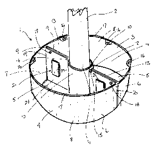
Figure 1 is a perspective view of an embodiment of the
mufti functional flower pot system according to the
present invention fully assembled as it would rest on a
patio table encircling an umbrella pole.
Figure 2 is a side plan view of one of the two identical
cylinder pot halves of the mufti functional flower pot
of Figure 1;
Figure 3 is a top plan view of the cylinder pot halve of
Figure 2;
Figure 4 is a is a perspective view of an embodiment of
the mufti functional flower pot system fully assembled as
it would rest in the middle of a patio table without the
umbrella pole but secured to the table using a stabilizer
according to the present invention;
CA 02345160 2001-04-25
- 6 -
Figure 5 is a side plan view, partially in cross-section,
of the stabilizer shown in Figure 4 as it would appear
being pushed down through the hole in the centre of the
patio table when the umbrella pole is not in use;
Figure 6 is a side plan view, partially in cross section,
of the stabilizer of Figure 5 as it would rest in the
centre hole of the patio table when the umbrella pole is
not in use, its top resting on the patio table and its
body protruding downward below the table level;
Figure 7 is a side plan view, partially in cross section,
of one of the two identical cylinder pot halves of Figure
4;
Figure 8 is a side plan view, partially in cross section,
of another embodiment of a stabilizer according to the
present invention as it would rest in the centre hole of
the patio table when the umbrella pole is not in use, its
top resting on the patio table and its body protruding
downward below the table level;
Figure 9 is a side plan view, partially in cross section,
of one of the two identical cylinder pot halves with the
stabilizer of Figure 8;
Figure 10 is a is a perspective view of an embodiment of
the mufti functional flower pot system fully assembled as
it would hang from a three string hanger held by a hanger
secured to a wall or fence;
Figure 11 is a cross section of the mufti functional
flower pot of Figure 3 along line A-A;
Figure 12 is a is a perspective view of another
embodiment of the mufti functional flower pot system
CA 02345160 2001-04-25
7
according to the present invention fully assembled as it
would rest on a table, counter or other flat surface;
Figure 13 is a side plan view, partially in cross
section, of one of the two identical cylinder pot halves
of the mufti functional flower pot of Figure 12.
Figure 14 is a side plan view, partially in cross
section, of another embodiment of a stabilizer according
to the present invention as it would rest in the centre
hole of the patio table when the umbrella pole is not in
use, its top resting on the patio table and its body
protruding downward below the table level;
Figure 15 is a side plan view partially in cross section,
of the stabilizer of Figure 14 shown depending through
adjoining pot sections;
Figure 16 is a side plan view partially in cross section
of another embodiment of a stabilizer according to the
present invention.
DETAILED DESCRIPTION OF THE PREFERRED EMBODIMENTS
Referring to Figures 1 to 3, a preferred embodiment of a
multifunctional flower pot according to the present
invention is generally indicated at 1. Figure 1
illustrates the preferred embodiment of the mufti
functional flower pot system fully assembled as it would
rest on a patio table encircling an umbrella pole 2. The
mufti functional flower pot 1 has at least two pot
sections, preferably two identical pot halves 3,4, each
having a base 5 and at least two side walls 6 to define
an enclosed space 7 open at the top. In the embodiment
illustrated the base 5 has a semi-circular configuration,
a first curved wall 8 and a generally planar wall 9. The
planar wall 9 has an indent section 10 which forms the
CA 02345160 2001-04-25
_ g
umbrella pole passageway 11 when the halves 3,4 are
joined. In the preferred embodiment the indent section 10
has a semi-circular cross section and is centered on
planar wall 9. In the preferred embodiment illustrated, a
notch or groove 12 is located in the top edge 13 of
planar wall section 9 adjacent to each of the ends 14, 15
of the semi-circular indent section 10. Along the
interior of the top edge 13 of the curved wall 8 hook
protrusions 16 are provided. In the embodiment
illustrated the hook protrusions are spaced equidistant
along the top edge 17 of curved wall 8. Holes 18 are
located in planar wall 9 to permit either or both of the
pot halves 3,4 to be attached to a vertical surface such
as a wall or fence utilizing a suitable fastener such as
nails, screws, hooks or the like. Holes 18 in the
embodiment in Figure 1 are located below the top edge 13
of the planar wall 9 adjacent the points of connection
19, 20 of the planar wall 9 with the curved wall section
8. In order to permit the pot halves 3,4 to be easily
joined and separated attachment means, generally
indicated at 21, are located on the planar wall 9 of each
of the pot halves 3,4. In the embodiment illustrated, the
attachment means 21 comprises a pair of magnets 22, 23
permanently secured to the inside surface 24 of planar
wall 9 about half way between the base 5 and top edge 13
of the planar wall 9 and half way between the ends 14, 15
of the semi-circular indent section 10 and the points of
connection 19, 20 of the planar wall 9 and the curved
wall 8. The attachment means 21 do not require lifting
one or both pot sections relative to the other in order
to join or separate the pot sections. Further the
attachment means 21 permits the pot sections to be easily
joined or separated regardless of whether the pot
sections are full or empty.
Figure 2 is a side plan view looking at the planar wall 9
of one of the two identical pot halves 3,4 of the
CA 02345160 2001-04-25
- 9 -
preferred embodiment of Figure 1 showing the umbrella
pole passageway 11 formed by the semi-circular indent
section 10 in the planar wall 9. The umbrella passageway
11 extends from the base 5 to the top edge 13 of planar
wall 9.
Figure 3 is a top plan view of one of the two identical
pot halves 3,4 of the preferred embodiment of Figure 1.
The hook protrusions 16 are adapted to allow the
attachment of a hanger when the pot is used as a hanging
basket (see Figures 10 and 11). The protrusions 16 are
set every 60 degrees around the circumference of the top
edge 17 of curved wall 8.
Figures 4 to 6 illustrate the preferred embodiment of the
mufti functional flower pot system 1 fully assembled as
it would rest in the middle of a patio table without the
umbrella pole but secured to the table using a
stabilizer, generally indicated at 25, in accordance with
the present invention. The stabilizer 25 consists of a
cap 26, longitudinal depending section 27 and connection
means, generally indicated at 28. The cap 26 of
stabilizer 25 is designed to cover the passageway 11
formed by the semi-circular indent sections 10 of pot
halves 3,4 where the umbrella pole would normally
project. In the embodiment in Figures 4 to 7, the cap 26
has a generally circular planar portion 29 and depending
peripheral flange 30 which fits into the notches/grooves
12 on the top edge 13 of the planar wall 9. A hole 31 is
centrally disposed in cap 26 to permit the cap to be
lifted by a person's finger.
Figure 5 is a side plan view partially in cross section
of the stabilizer 25 as it would appear being pushed down
through the hole 32 in the centre of the patio table 33
when the umbrella pole is not in use. The longitudinal
depending section 27 of stabilizer 25, in the embodiment
CA 02345160 2001-04-25
- 10 -
shown, consists of tubular body 34 with a diameter
slightly less than that of the patio table centre hole
32. One end 35 of the tubular body 34 is attached to cap
26. Connection means 28 consist of two diagonally
opposite depending fingers 36 which arch out and upward
from a base plate 37 attached to the other end of tubular
body 34. To allow the fingers 36 of the stabilizer 25 to
pass through the hole 32 in the centre of the patio table
33, the tubular body 34 of the stabilizer 25 has been
designed with indents 39 of sufficient depth to
accommodate the fingers 36 when they are forced inward as
a result of the stabilizer 25 being pushed through the
hole 32. Once the stabilizer 25 has passed through the
hole 32, the fingers 36 are biased to spread open as
shown in Figure 6. To allow the placement of the umbrella
pole, the stabilizer 25 is removed from the hole by
squeezing the two fingers 36 together under the patio
table 33 and pushing it back up through the hole 32.
Figure 6 is a side plan view partially in cross section
of the stabilizer 25 as it would rest in the centre hole
32 of the patio table 33 when the umbrella pole is not in
use. The edge of peripheral flange 30 of cap 26 rests on
the top 40 of patio table 33 with the tubular body 34
protruding downward below the table level. The two
fingers 36 arch out and upward from the base plate 37
toward the bottom side 41 of the table 33 with a spread
greater than the diameter of the patio table hole 32. The
fingers 36 are biased to spread open thereby preventing
the stabilizer 25 from being accidentally pulled upward
through the hole 32 but permit the stabilizer to be
stretched to the top edge 13 of the planar wall 9 of the
two pot halves 3,4 and then fitted to them holding the
pot halves to the table.
Figure 7 is a side plan view partially in cross section
of one of the two pot halves 3,4, showing the stabilizer
CA 02345160 2001-04-25
- 11 -
25 with its cap 26 fitted over the umbrella passageway
opening 11 and protruding downward through the passageway
and the centre hole 32 of the patio table 33. The two
fingers 36 spread under the table 33 providing the
holding action. Further, the tubular body 34 of the
stabilizer 25 protrudes downward through the hole 32
below the patio table 33 limiting the sideways movement
of the flower pot system.
Figure 8 is a side plan view partially in cross section,
of the stabilizer 25 with an alternative flat top 42
rather than the cap 26 having a peripheral flange as
shown in Figure 4-7. The advantage of the stabilizer's 25
flat top 42 is its ability to lie flat on the patio table
33 when at rest and not interfere with objects placed on
the table such as plates which would be impacted by the
cap 26 with peripheral flange of Figures 4-7. The
stabilizer 25 can retain the pot halves 3,4 on the table
regardless of whether the stabilizer cap is designed flat
or with a peripheral flange.
Figure 9 is a side plan view partially in cross section
showing the alternative flat top design of the stabilizer
of Figure 8 with the pot halves.
Figure 10 illustrates the preferred embodiment of the
multi functional flower pot system 1 fully assembled as
it would hang from a three string hanger 43 for use as a
hanging basket. The magnets 22,23 and the stabilizer 25
hold the two pot halves 3,4 together exactly as they
would when the pot halves 3,4 are resting on the patio
table without the umbrella pole in place. The three
string hanger 43 is connected to the hook protrusions 16
to holds up the pot system and provides the balance
required to rest level in the air.
CA 02345160 2001-04-25
- 12 -
Figure 11 is a side plan view in partial cross section of
the preferred embodiment in Figure 10, showing the
stabilizer 25 with its cap 26 fitted over the umbrella
passageway opening 11 and protruding downward through the
passageway and showing the two fingers 36 spread under
the base 5 of the two pot halves 3,4.
Figure 12 illustrates a second preferred embodiment of
the mufti-functional flower pot system, generally
indicated at 50 fully assembled as it would rest on a
table, counter or other flat surface. The construction is
similar to that shown in Figures 1-11 but without the
umbrella passageway. In Figure 12 the two identical pot
halves 51,52, each include a curved wall 53, a planar
wall 54 without an umbrella pole passageway formed into
its mid portion, and a base 55. The curved wall 53,
planar wall 54 and base 55 define an enclosed space 56
open at the top 57. Magnets 58 permanently secured to the
planar wall 54 and bar stabilizer 59 clipped over the top
edge 60 of the planar walls 54 hold the pot halves 51,52
together.
Figure 13 is a side plan view of the second preferred
embodiment in Figure 12, showing one of the two identical
pot halves 51,52 without the umbrella pole passageway
formed into the mid portion of the planar walls 54 the
pot halves 51, 52. As in the embodiment shown in Figures
1-11, holes 61 are located at the top of each side of the
planar walls 54 to permit either or both of the pot
halves 3,4 to be attached to a vertical surface such as a
wall or fence utilizing a suitable fastener such as
nails, screws, hooks or the like. In order to permit the
pot halves 51,52 to be easily joined and separated
attachment means, generally indicated at 62, are located
on the planar wall 54 of each of the pot halves 51,52. In
the embodiment illustrated, the attachment means 62
comprises a pair of magnets 63 and bar stabilizer 59. The
CA 02345160 2001-04-25
- 13 -
magnets 63 are secured to the inside surface 64 of planar
wall 54 about half way between the base 55 and top edge
60 of the planar wall 54 and a quarter the way between
the ends 65, 66 of the planar wall 54.
Figures 14 and 15 illustrate another embodiment of a
stabilizer, generally indicated at 80, in accordance with
the present invention. The stabilizer 80 consists of a
cap 81, longitudinal depending section 82 and connection
means, generally indicated at 83. The cap 81 of
stabilizer 80 is designed to cover the umbrella pole
passageway 11 between adjoining pot halves 3,4 where the
umbrella pole would normally project. In the embodiment
in Figures 14 and 15, the cap 81 has a generally circular
planar portion 84 which fits over the umberella pole
passageway 11. A hole 85 is centrally disposed in cap 81
to permit the cap to be lifted by a person's finger.
Figure 14 shows the stabilizer 80 as it would appear
pushed down through the hole 32 in the centre of the
patio table 33 when the umbrella pole is not in use. The
longitudinal depending section 82 of stabilizer 80, in
the embodiment shown, consists of first tubular body 86
with a diameter slightly less than that of the patio
table centre hole 32. One end 87 of the tubular body 86
is attached to cap 81. Connection means 83 consist of two
diagonally opposite depending fingers 88 which arch out
and upward from a base plate 89 attached to the end 90 of
a second tubular body 91. The second tubular body 91 is
moveable within the first tubular body 86. A spring means
92 connected at one end to base plate 89 and at the other
end to a lateral flange 93 in the first tubular body 86
below the cap 81. The spring means 92 biases the second
tubular body 90 within the first tubular body 86 permit
adjustment for different thickness of tables and
different pot sizes. To allow the fingers 88 of the
stabilizer 80 to pass through the hole 32 in the centre
of the patio table 33, the first tubular body 86 of the
CA 02345160 2001-04-25
- 14 -
stabilizer 80 has been designed with indents 93 of
sufficient depth to accommodate the fingers 88 when they
are forced inward as a result of the stabilizer 80 being
pushed through the hole 32. Once the stabilizer 80 has
passed through the hole 32, the fingers 88 are biased to
spread open as shown in Figure 14 and 15. The cap 81
rests on the top 40 of patio table 33 with the second
tubular body 91 protruding downward below the table
level. The two fingers 88 arch out and upward from the
base plate 89 toward the bottom side 41 of the table 33
with a spread greater than the diameter of the patio
table hole 32. The fingers 88 are biased to spread open
thereby preventing the stabilizer 80 from being
accidentally pulled upward through the hole 32 but permit
the stabilizer to be stretched to the top edge 13 of the
planar wall 9 of the two pot halves 3,4 and then fitted
to them holding the pot halves to the table.
Figure 15 is a side plan view partially in cross section
of one of the two pot halves 3,4, showing the stabilizer
80 with its cap 81 fitted over the umbrella passageway
opening 11 and protruding downward through the passageway
and the centre hole 32 of the patio table 33. The two
fingers 88 spread under the table 33 providing the
holding action. Further, the first and second tubular
body 86, 91 of the stabilizer 80 protrudes downward
through the hole 32 below the patio table 33 limiting the
sideways movement of the flower pot system. The spring
means 92 accommodates the different thickness of the
table versus the table and pot sections or just the pot
sections.
Figure 16 illustrates a further embodiment of a
stabilizer, generally indicated at 100, in accordance
with the present invention. The stabilizer 100 consists
of a cap 101, longitudinal depending section 102 and
connection means, generally indicated at 103. The cap 101
CA 02345160 2001-04-25
- 15 -
of stabilizer 100 is designed to cover the passageway 11
formed by the semi-circular indent sections 10 of pot
halves 3,4 where the umbrella pole would normally
project. A hole 10g is centrally disposed in cap 101 to
permit the cap to be lifted by a person's finger.
The longitudinal depending section 102 of stabilizer 101,
in the embodiment shown, consists of tubular body 104
with a diameter slightly less than that of the patio
table centre hole 32. One end 105 of the tubular body 104
is attached to cap 101. Connection means 106 consist of a
nut 107 which threads on to the other end 108 tubular
body 104. Once the stabilizer 100 has passed through the
hole 32, the nut 107 is screwed on to the threaded end
108 of tubular body 104 to them holding the pot halves to
the table. Where the pot is used as a hanging basket
stabilizer 100 helps hold the pot sections together with
nut 107 threaded tight to the base of the pot.
The principles of the present invention can be applied to
pots having any shape not just the circular design shown
in the Figures. The pot can be square, oval, triangular
or other form of polygon. Both pot halves do necessarily,
but preferably are, identical shapes. The attachment
means whether utilizing either alone or in combination a
stabilizer, magnets, mechanical fasteners or other means
must be complementary on both pot halves. The pots can be
used for planting flowers or can be shaped to hold other
items such as food, cutlery, condiments etc. The present
invention does not require in each case all of the
possible methods to be employed to hold the pot halves
together. One or more methods or any combination thereof
can be utilized.
Having illustrated and described a preferred embodiment
of the invention and certain possible modifications
thereto, it should be apparent to those of ordinary skill
in the art that the invention permits of further
CA 02345160 2001-04-25
- 16 -
modification in arrangement and detail.
It will be appreciated that the above description related
to the preferred embodiment by way of example only. Many
variations on the invention will be obvious to those
knowledgeable in the field, and such obvious variations
are within the scope of the invention as described and
claimed, whether or not expressly described.