Language selection

Search

Patent 2345268 Summary

Third-party information liability

Some of the information on this Web page has been provided by external sources. The Government of Canada is not responsible for the accuracy, reliability or currency of the information supplied by external sources. Users wishing to rely upon this information should consult directly with the source of the information. Content provided by external sources is not subject to official languages, privacy and accessibility requirements.

Claims and Abstract availability

Any discrepancies in the text and image of the Claims and Abstract are due to differing posting times. Text of the Claims and Abstract are posted:

  • At the time the application is open to public inspection;
  • At the time of issue of the patent (grant).
(12) Patent: (11) CA 2345268
(54) English Title: VESSEL APERTURE ADAPTER
(54) French Title: ADAPTATEUR POUR OUVERTURE DE RECIPIENT
Status: Term Expired - Post Grant Beyond Limit
Bibliographic Data
(51) International Patent Classification (IPC):
  • B65B 01/04 (2006.01)
  • B65B 39/00 (2006.01)
  • F16L 41/03 (2006.01)
(72) Inventors :
  • SCHENK, WILLIAM P. (United States of America)
(73) Owners :
  • ROBERTSHAW CONTROLS COMPANY
(71) Applicants :
  • ROBERTSHAW CONTROLS COMPANY (United States of America)
(74) Agent: SMART & BIGGAR LP
(74) Associate agent:
(45) Issued: 2009-01-20
(86) PCT Filing Date: 2000-07-24
(87) Open to Public Inspection: 2001-02-01
Examination requested: 2005-07-25
Availability of licence: N/A
Dedicated to the Public: N/A
(25) Language of filing: English

Patent Cooperation Treaty (PCT): Yes
(86) PCT Filing Number: PCT/US2000/020200
(87) International Publication Number: US2000020200
(85) National Entry: 2001-03-23

(30) Application Priority Data:
Application No. Country/Territory Date
09/480,751 (United States of America) 2000-01-10
60/145,583 (United States of America) 1999-07-26

Abstracts

English Abstract


An adapter (10) is provided
for facilitating simultaneous level-monitoring
and filling of a vessel (26) through a single
vessel aperture. The adapter (10) comprises
an aperture engagement end (18) which is
adapted to couple with the aperture of a vessel
(26). The adapter (10) includes a plurality
of inlets (30, 38), pathways (34, 42, 46) and
outlets (54, 64), wherein a first pathway (34) is
substantially straight and is adapted to receive
a level-monitoring device (68).


French Abstract

L'invention concerne un adaptateur (10) permettant de faciliter simultanément la surveillance d'un niveau et le remplissage d'un récipient (26) par l'intermédiaire d'une seule ouverture de récipient. Cet adaptateur (10) comprend une extrémité d'engagement (18) d'ouverture conçue pour être couplée à l'ouverture dudit récipient (26). Ledit adaptateur (10) comprend également une pluralité d'entrées (30, 38), des passages (34, 42, 46), et des sorties (54, 64), un premier passage (34) étant sensiblement droit et conçu pour recevoir un dispositif de surveillance (68) de niveau.

Claims

Note: Claims are shown in the official language in which they were submitted.


CLAIMS
1. An adapter for facilitating simultaneous level-
monitoring and filling of a vessel through an aperture,
the adapter comprising:
an inlet end and an aperture engagement end, wherein
said inlet end includes a plurality of inlets, and said
aperture engagement end is adapted for being coupled with
the aperture of a vessel;
said adapter having first, second and third
pathways, wherein said first pathway extends from a first
inlet to a first outlet, and said second pathway extends
from a second inlet to a second outlet, and said third
pathway extends from a third inlet to said first outlet;
said first pathway being substantially straight to
provide a straight line of sight therethrough;
said first pathway being sized and shaped to receive
a level-monitoring device; and
said second pathway being free from fluid
communication with said first pathway and said third
pathway.
14

2. The adapter of claim 1, wherein said straight
line of sight is substantially vertical when said
adapter is coupled with the aperture.
3. The adapter of claim 2, wherein said first
pathway is sized and shaped to receivably maintain the
level-monitoring device in a substantially vertical
orientation.
4. The adapter of claim 3, wherein said first
pathway comprises a level-monitoring conduit.
5. The adapter of claim 3, wherein at least a
portion of said second outlet extends divergently from
said first outlet.
6. The adapter of claim 3, wherein said second
outlet is offset from said first outlet.
7. The adapter of claim 6, wherein said second
pathway extends further in a downstream direction than
said first outlet.

8. The adapter of claim 3, wherein said second
inlet is sized and shaped to receive a fill nozzle
therein.
9. The adapter of claim 3, further comprising an
endcap fitting sized and shaped to engage a cap to close
both said second inlet and said third inlet.
10. The adapter of claim 3, wherein said first
inlet is internally threaded.
11. The adapter of claim 3, further comprising a
level-monitoring device disposed in said first pathway.
12. An adapter for facilitating simultaneous level-
monitoring and filling of a vessel through a bung hole,
the adapter comprising:
an inlet end and an aperture engagement end, wherein
said inlet end includes a plurality of inlets, and said
aperture engagement end is adapted for being coupled with
the bung hole of a vessel;
said adapter having a first pathway and a second
pathway, wherein said first pathway extends from a first
16

inlet to a first outlet and said second pathway extends
from a second inlet to a second outlet;
said second pathway being free from fluid
communication with said first pathway; and
a level-monitoring device disposed in said first
pathway.
13. The adapter of claim 12, wherein said level
monitoring device is a device selected from the group
consisting of a capacitance level-monitoring device, a
laser level-monitoring device, an ultrasonic level-
monitoring device, a radar level-monitoring device and a
float type level-monitoring device.
14. The adapter of claim 12, wherein said first
pathway is substantially straight to provide a straight
line of sight into said aperture.
15. The adapter of claim 12, further comprises a
third pathway extending from a third inlet to said first
outlet.
17

16. The adapter of claim 15, wherein said second
pathway is free from fluid communication with said first
pathway and said third pathway.
17. A method for simultaneously filling and
monitoring the material level of a vessel through a
single aperture, said method comprising the steps of:
(a) providing an adapter having an inlet end and an
aperture engagement end, wherein the inlet end includes a
plurality of inlets, and the aperture engagement end is
adapted for being coupled with the aperture of a vessel;
the adapter having first, second and third pathways,
wherein the first pathway extends from a first inlet to a
first outlet, and the second pathway extends from a
second inlet to a second outlet, and the third pathway
extends from a third inlet to a first outlet;
the first pathway being substantially straight to
provide a straight line of sight therethrough;
the first pathway being sized and shaped to receive
a level-monitoring device; and
the second pathway being free from fluid
communication with the first pathway and the third
pathway.
18

(b) engaging the aperture engagement end with the
vessel aperture;
(c) providing a level-monitoring device;
(d) installing the level-monitoring device into the
first pathway;
(e) filling the vessel through the second pathway
of the adapter;
(f) monitoring the material level in the vessel with
the level-monitoring device; and
(g) wherein the adapter facilitates the simultaneous
filling and fluid level-monitoring of the vessel through
a single aperture.
19

Description

Note: Descriptions are shown in the official language in which they were submitted.


CA 02345268 2001-03-23
WO 01/07322 PCT/LJS00/20200
VESSEL APERTURE ADAPTER
This application claims priority to U. S Application
serial no. 09/480,751 entitled Vessel Aperture Adapter
filed on 1/10/00 and U.S. Provisional Patent Application
serial No. 60/145,583 entitled Two Bung Tank Adapter for
Level Monitoring System filed July 26, 1999.
BACKGROUND
Storage tanks or vessels have apertures that are
used for various purposes. Typically, one of these
apertures is used for permanently installing a pump.
Other vessel apertures are used for filling, installing a
level-monitoring device and for installing a sight-gauge
or other devices.
A level-monitoring device installed in a vessel
aperture makes it easy to quickly monitor the level of
liquid or solid in a vessel. Simplifying the level-
monitoring leads to more frequent monitoring of the
vessel and therefore lowers the chances of unexpectedly
finding empty vessels. For example, if the vessel is a
diesel fuel storage tank on a farm, and the tank
unexpectedly becomes empty, this will cause downtime on
the farm equipment. This may also cause downtime for
1

CA 02345268 2001-03-23
WO 01/07322 PCT/tJS00/20200
equipment operators while they wait for more fuel to be
delivered.
Many older vessels have only two apertures. One of
these apertures usually has a permanently installed pump
and this leaves only one available aperture for filling
and everything else.
If the owner wants to prevent unexpected empty
tanks, he may install a level-monitoring device in this
available aperture. However, every time the vessel needs
to be filled, the monitor device must be removed, the
tank filled and then the monitor device reinstalled.
This is time consuming, may damage the level-monitoring
device and may lead to the device being lost or not being
reinstalled.
One proposed solution is to install more apertures
into a vessel, however this requires many steps. First,
the vessel must be completely empty, moreover, if it is a
fuel tank, it needs to be filled with water to prevent a
flash fire while drilling. Next, a vertical opening must
be drilled into the vessel, and then a threaded collar
must be permanently vertically installed into the
aperture. Finally, all of the water and debris must be
2

CA 02345268 2001-03-23
WO 01/07322 PCT/US00/20200
cleaned from the tank. This process is expensive, time
consuming and may be dangerous if performed improperly.
Another drawback associated with vessel apertures is
backflow, which is the fluid that spills out of the
vessel during the vessel filling process. Backflow is
generated by air venting up into the fluid coming down
the fill nozzle. Backflow wastes fuel, is bad for the
environment and slows down the filling process.
For the foregoing reasons, there is a need for an
adapter which allows simultaneous filling and level-
monitoring through a single vessel aperture. There is
also a need for an adapter that can fill a vessel with
minimal fluid backflow.
SLJbIIKARY
The present invention is directed to an adapter that
satisfies this need for simultaneous level-monitoring and
filling of a vessel through a single vessel aperture.
The adapter also satisfies the need for reducing the
backflow that may occur while filling a vessel.
Accordingly, the invention provides in one aspect an
adapter including an inlet end having a plurality of
3

CA 02345268 2001-03-23
WO 01/07322 PCT/U300/20200
inlets and an aperture engagement end for coupling with
an aperture of a vessel. This adapter has three
pathways, wherein the first pathway is substantially
straight, provides a straight line of sight therethrough
and is adapted to receive a level-monitoring device
therein. The first pathway extends from a first inlet to
a first outlet. The second pathway extends from a second
inlet to a second outlet. The third pathway extends from
a third inlet to the first outlet. The second pathway is
free from fluid communication with the first and third
pathways.
In an alternative embodiment, the adapter may
include, for example, a level-monitoring device disposed
in the first inlet. In addition, the adapter may further
comprise an endcap fitting adapted to receive a cap to
simultaneously close both the second inlet and the third
inlet.
The present invention provides, irl a different
aspect, a method for simultaneously filling and
monitoring the material level of the vessel through a
single aperture.
This method includes providing an adapter having an
inlet end and an aperture engagement end, in which the
4

CA 02345268 2001-03-23
WO 01/07322 PCT/US00/20200
inlet end includes a plurality of inlets, and the
aperture engagement end is adapted for being coupled with
the aperture of a vessel. The adapter has first, second
and third pathways, in which the first pathway extends
from a first inlet to a first outlet, the second pathway
extends from a second inlet to a second outlet, and the
third pathway extends from a third inlet to a first
outlet. The first pathway is substantially straight to
provide a straight line of sight therethrough and is also
adapted to receive a level-monitoring device therein.
The second pathway is free from fluid communication with
the first pathway and the third pathway.
Subsequent steps include coupling the aperture
engagement end with the vessel aperture and installing a
level-monitoring device into the first pathway. The
vessel is then filled through the second pathway of the
adapter. An additional step includes monitoring the
material level in the vessel with the level-monitoring
device.
The above and other features and advantages of
this invention will be more readily apparent from a
reading of the following detailed description of

CA 02345268 2001-03-23
WO 01/07322 PCT/US00/20200
various aspects of the invention taken in conjunction
with the accompanying drawings.
BRIEF DESCRIPTION OF THE DRAWINGS
Fig. 1 is a perspective view of a version of the
adapter;
Fig. 2 is a front longitudinal offset sectional
view, of the adapter taken along 2-2 of Fig. 1;
Fig. 3 is a top plan view of the adapter taken along
3-3 of Fig. 2; and
Fig. 4 is a bottom plan view of the adapter taken
along 4-4 of Fig. 2.
DETAILED DESCRIPTION OF THE PREFERRED E1rIDODIMENTS
Referring to the figures set forth in the
accompanying Drawings, the illustrative embodiments of
the present invention will be described in detail
hereinbelow.
For clarity of exposition, like features shown in
the accompanying Drawings shall be indicated with like
reference numerals and similar features as shown in
6

CA 02345268 2001-03-23
WO 01/07322 PCT/US00/20200
alternate embodiments in the Drawings shall be
indicated with similar reference numerals.
Where used in this disclosure, the term "bung
hole" when used in connection with an element
described herein, shall refer to an aperture within a
stationary storage tank or vessel which is used for
filling, level-monitoring, venting or other uses.
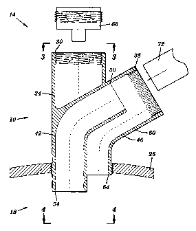
The present invention is an adapter 10 that
satisfies the need for simultaneous level-monitoring and
filling of a vessel 26 through a single vessel aperture
22. The adapter 10 also satisfies the need for reducing
the backflow that may occur while filling a vessel 26.
As shown in Fig. 1, the adapter 10 has an inlet
end 14 and an aperture engagement end 18. The inlet
end 14 has a plurality of inlets. The aperture
engagement end 18 extends through an aperture such as
vessel aperture 22 to couple thereto. The aperture
may be disposed in a tank, barrel or container such as
the vessel 26. The adapter 10 is fabricated from
metal, or alternatively from other materials such as
plastic or composites.
In a preferred embodiment, as best shown in Fig.
2, the inlet end 14 has two openings; a first inlet
7

CA 02345268 2001-03-23
WO 01/07322 PCT/US00/20200
30, which leads into a first pathway 34 and an other
opening referred to herein as an end cap fitting 38.
The end cap fitting 38 leads into both the second
pathway 42 and the third pathway 46.
The second pathway 42 extends from a second inlet
50 to a second outlet 54. The third pathway 46
extends from a third inlet 60, merges with the first
pathway 34 and then terminates at the first outlet 64.
The first pathway 34 extends from a first inlet 30,
merges with the third pathway 46 and terminates with
the first outlet 64. The aperture engagement end 18
has two openings, the first outlet 64 and the second
outlet 54. The second pathway 42 is separate from the
third pathway 46 and the first pathway 34. The third
pathway 46 and first pathway 34 begin as two separate
pathways and then merge into one single pathway that
terminates at the first outlet 64.
In another embodiment, a level-monitoring device
68 extends into the first pathway 34, and couples with
the first inlet 30. Also shown in Fig. 2 is a fill
pipe (i.e., nozzle) 72 that may be inserted into the
second pathway 42 to fill the vessel 26.
8

CA 02345268 2001-03-23
WO 01/07322 PCTIUSOO/20200
Fig. 3 shows the third pathway 46 merging with
the first pathway 34 and both of them terminating at
the first outlet 64. The first inlet 30 may have
internal threads 76. The end cap fitting 38 may also
have internal threads 80. As also shown, the second
pathway 42 is preferably sized and shaped to receive a
standard fill pipe 72.
In a preferred embodiment, as shown in Fig. 4,
the first pathway 34 is substantially straight. As
discussed hereinabove, the first pathway 34 extends
from the first outlet 64 through the adapter 10 and
terminates at the first inlet 30. The second outlet
54 is located at the aperture engagement end 18 of the
second pathway 42. The second inlet 50 of the second
pathway 42 is located at the inlet end 14. The
aperture engagement end 18 is coupled with the vessel
26 by using any conventional coupling means such as
external threads 84. In this regard, it should be
recognized that engagement end 18 may be coupled with
the vessel 26 using any number of techniques well-
known to those skilled in the art, including, for
example, internal threads, bayonet couplings, quick
release couplings, quarter-turn couplings, press-fit
9

CA 02345268 2001-03-23
WO 01/07322 PCT/US00/20200
engagement, chemical bonding (i.e., adhesive), and by
forming the end 18 integrally with the vessel 26, etc.
Many older vessels have only two apertures. A
pump is usually permanently installed in one of the
apertures. This leaves only one aperture available
for filling, level-monitoring, venting and all other
uses. Adapter 10, of the present invention,
facilitates simultaneous level-monitoring, reduced
backflow filling and venting of a vessel through a
single aperture without the disadvantages of having to
remove and reinstall the level monitoring device each
time the vessel is filled. The expensive process of
installing additional apertures into a vessel or
having to purchase a new vessel is also avoided by
using the adapter 10.
The present invention has many advantages
relative to the prior art. For example, the first
pathway 34 advantageously provides a straight line of
sight into the vessel 26. The straight line of sight
allows nominally any conventional level-monitoring
device to operate with the adapter 10. Examples of
such devices include capacitance, ultrasonic, laser,
radar and float type level-monitoring devices.

CA 02345268 2001-03-23
WO 01/07322 PCT/US00/20200
Moreover, the first inlet 30 is sized and shaped,
and/or otherwise adapted to conveniently couple with
most conventional level-monitoring devices.
It this regard, it should be recognized that any
configuration of a first pathway 34 having a
substantially straight line of sight, may be used with
a conventional level-monitoring device and thus be
construed to be within the scope of the present
invention. Moreover, first inlet 30 of the first
pathway 34 may be coupled with such level monitoring
devices using any number of techniques well-known to
those skilled in the art, including, for example,
internal threads, bayonet couplings, quick release
couplings, quarter-turn couplings, press-fit
engagement, chemical bonding (i.e., adhesive), etc.,
without departing from the spirit and scope of the
present invention.
In addition, backflow is minimized by providing
separate pathways 42 and 46 for filling and for
venting, respectively.
Moreover, separation of the second pathway 42
from the first pathway 34 advantageously serves to
help prevent damage to the level-monitoring device 68
11

CA 02345268 2001-03-23
WO 01/07322 PCT/US00/20200
from the fill nozzle 72. The second outlet 54 is also
preferably angled to direct the fluid or solid fill
material away from a level-monitoring device disposed
in the first pathway 34.
Still further, to minimize damage to the level-
monitoring device 68 while filling the vessel 26, the
second outlet 54 is not coterminous with the first
outlet 64 but rather, extends further into the vessel
26 than first outlet 64. This also helps to keep the
fluids or solids away from the level-monitoring device
68.
Although the invention has been shown and
described with respect to a curved second pathway, it
should be understood by those skilled in the art that
the second pathway may be substantially straight as
long as it is separate and discrete from the other
pathways, without departing from the spirit and scope
of the present invention.
The foregoing description is intended primarily for
purposes of illustration. Although the invention has
been shown and described with respect to an exemplary
embodiment thereof, it should be understood by those
skilled in the art that the foregoing and various other
12

CA 02345268 2001-03-23
WO 01/07322 PCTIUSOO/20200
changes, omissions, and additions in the form and detail
thereof may be made therein without departing from the
spirit and scope of the invention.
Having thus described the invention, what is
claimed is:
13

Representative Drawing
A single figure which represents the drawing illustrating the invention.
Administrative Status

2024-08-01:As part of the Next Generation Patents (NGP) transition, the Canadian Patents Database (CPD) now contains a more detailed Event History, which replicates the Event Log of our new back-office solution.

Please note that "Inactive:" events refers to events no longer in use in our new back-office solution.

For a clearer understanding of the status of the application/patent presented on this page, the site Disclaimer , as well as the definitions for Patent , Event History , Maintenance Fee  and Payment History  should be consulted.

Event History

Description Date
Inactive: Expired (new Act pat) 2020-07-24
Common Representative Appointed 2019-10-30
Change of Address or Method of Correspondence Request Received 2018-03-28
Inactive: Late MF processed 2015-09-02
Letter Sent 2015-07-24
Amendment Received - Voluntary Amendment 2014-06-25
Inactive: Reversal of will be deemed expired status 2010-10-06
Inactive: Office letter 2010-10-06
Letter Sent 2010-07-26
Inactive: Single transfer 2009-01-29
Letter Sent 2009-01-29
Grant by Issuance 2009-01-20
Inactive: Cover page published 2009-01-19
Pre-grant 2008-10-30
Inactive: Final fee received 2008-10-30
Notice of Allowance is Issued 2008-06-04
Letter Sent 2008-06-04
Notice of Allowance is Issued 2008-06-04
Inactive: Approved for allowance (AFA) 2008-05-12
Amendment Received - Voluntary Amendment 2008-01-04
Inactive: S.30(2) Rules - Examiner requisition 2007-12-10
Letter Sent 2007-10-11
Reinstatement Requirements Deemed Compliant for All Abandonment Reasons 2007-09-14
Amendment Received - Voluntary Amendment 2007-09-14
Reinstatement Request Received 2007-09-14
Amendment Received - Voluntary Amendment 2007-09-14
Inactive: Delete abandonment 2007-06-13
Inactive: Abandoned - No reply to s.29 Rules requisition 2007-03-07
Amendment Received - Voluntary Amendment 2007-02-26
Inactive: S.29 Rules - Examiner requisition 2006-09-07
Inactive: S.30(2) Rules - Examiner requisition 2006-09-07
Letter Sent 2006-08-24
Inactive: IPC from MCD 2006-03-12
Letter Sent 2005-08-29
Amendment Received - Voluntary Amendment 2005-08-25
All Requirements for Examination Determined Compliant 2005-07-25
Request for Examination Requirements Determined Compliant 2005-07-25
Request for Examination Received 2005-07-25
Letter Sent 2005-07-21
Letter Sent 2004-04-28
Letter Sent 2002-06-25
Inactive: Single transfer 2002-05-02
Inactive: Cover page published 2001-06-13
Inactive: First IPC assigned 2001-06-06
Inactive: Courtesy letter - Evidence 2001-06-05
Inactive: Notice - National entry - No RFE 2001-05-31
Application Received - PCT 2001-05-28
Application Published (Open to Public Inspection) 2001-02-01

Abandonment History

Abandonment Date Reason Reinstatement Date
2007-09-14

Maintenance Fee

The last payment was received on 2008-06-19

Note : If the full payment has not been received on or before the date indicated, a further fee may be required which may be one of the following

  • the reinstatement fee;
  • the late payment fee; or
  • additional fee to reverse deemed expiry.

Patent fees are adjusted on the 1st of January every year. The amounts above are the current amounts if received by December 31 of the current year.
Please refer to the CIPO Patent Fees web page to see all current fee amounts.

Fee History

Fee Type Anniversary Year Due Date Paid Date
Basic national fee - standard 2001-03-23
Registration of a document 2002-05-02
MF (application, 2nd anniv.) - standard 02 2002-07-24 2002-06-25
MF (application, 3rd anniv.) - standard 03 2003-07-24 2003-06-18
Registration of a document 2004-04-02
MF (application, 4th anniv.) - standard 04 2004-07-26 2004-06-29
Registration of a document 2005-03-23
MF (application, 5th anniv.) - standard 05 2005-07-25 2005-06-23
Request for examination - standard 2005-07-25
MF (application, 6th anniv.) - standard 06 2006-07-24 2006-06-22
Registration of a document 2006-07-13
MF (application, 7th anniv.) - standard 07 2007-07-24 2007-06-18
Reinstatement 2007-09-14
MF (application, 8th anniv.) - standard 08 2008-07-24 2008-06-19
Final fee - standard 2008-10-30
Registration of a document 2008-11-07
MF (patent, 9th anniv.) - standard 2009-07-24 2009-06-19
MF (patent, 10th anniv.) - standard 2010-07-26 2010-06-18
MF (patent, 11th anniv.) - standard 2011-07-25 2011-06-22
MF (patent, 12th anniv.) - standard 2012-07-24 2012-06-14
MF (patent, 13th anniv.) - standard 2013-07-24 2013-06-12
MF (patent, 14th anniv.) - standard 2014-07-24 2014-07-09
MF (patent, 15th anniv.) - standard 2015-07-24 2015-09-02
Reversal of deemed expiry 2015-07-24 2015-09-02
MF (patent, 16th anniv.) - standard 2016-07-25 2016-07-06
MF (patent, 17th anniv.) - standard 2017-07-24 2017-06-28
MF (patent, 18th anniv.) - standard 2018-07-24 2018-07-04
MF (patent, 19th anniv.) - standard 2019-07-24 2019-07-03
Owners on Record

Note: Records showing the ownership history in alphabetical order.

Current Owners on Record
ROBERTSHAW CONTROLS COMPANY
Past Owners on Record
WILLIAM P. SCHENK
Past Owners that do not appear in the "Owners on Record" listing will appear in other documentation within the application.
Documents

To view selected files, please enter reCAPTCHA code :


To view images, click a link in the Document Description column. To download the documents, select one or more checkboxes in the first column and then click the "Download Selected in PDF format (Zip Archive)" or the "Download Selected as Single PDF" button.

List of published and non-published patent-specific documents on the CPD .

If you have any difficulty accessing content, you can call the Client Service Centre at 1-866-997-1936 or send them an e-mail at CIPO Client Service Centre.


Document
Description 
Date
(yyyy-mm-dd) 
Number of pages   Size of Image (KB) 
Representative drawing 2001-06-12 1 9
Description 2001-03-22 13 356
Claims 2001-03-22 6 138
Abstract 2001-03-22 1 50
Drawings 2001-03-22 3 61
Claims 2007-02-25 6 135
Claims 2008-01-03 6 131
Representative drawing 2009-01-04 1 12
Notice of National Entry 2001-05-30 1 193
Reminder of maintenance fee due 2002-03-25 1 113
Request for evidence or missing transfer 2002-03-25 1 108
Courtesy - Certificate of registration (related document(s)) 2002-06-24 1 134
Reminder - Request for Examination 2005-03-28 1 117
Acknowledgement of Request for Examination 2005-08-28 1 177
Courtesy - Abandonment Letter (R29) 2007-06-17 1 167
Notice of Reinstatement 2007-10-10 1 172
Commissioner's Notice - Application Found Allowable 2008-06-03 1 164
Maintenance Fee Notice 2015-09-01 1 170
Late Payment Acknowledgement 2015-09-01 1 163
Correspondence 2001-05-30 1 24
PCT 2001-03-22 2 86
Correspondence 2006-08-23 5 406
Correspondence 2008-10-29 1 38
Correspondence 2010-10-05 1 15