Note: Descriptions are shown in the official language in which they were submitted.
CA 02345451 2001-07-31
Process for the simultaneous electrochemical
preparation of sodium dithionite and sodium
peroxodisulfate
Nowadays, combined processes with oxidizing and
reducing bleaching sequences are increasingly used for
various chlorine-free bleaching processes, in
particular in the bleaching of paper and pulp. Here,
the reducing bleach is preferably sodium dithionir_e,
.LO and the oxidizing bleach is hydrogen peroxide. It has
also been suggested to use peroxodisulfates or
peroxomonosulfates, which can be prepared
electrochemically, as oxidizing bleaches (German patent
198 03 001). Peroxod:isulfates are exclusively prepared
.L5 by electrochemical means (J. Balej, H. Vogt
Electrochemical Reactors. In: Fortschritte der
Verfahrenstechrik, vol. 22, p. 361, VDI Verlag 1984).
Using an electrochemical combination process it is
20 possible to prepare sodium peroxodisulfate, in additiow
to sodium hydroxide solution, from sodium sulfate in a
two-chamber cell with can on exchanger membranes as
separators (EP 0846 194).
25 The use of an alkaline solution with a stoichiometric
composition of sodium peroxodisulfate and sodium
hydroxide solution has also been proposed for bleaching
and oxidation processes (German patent 44 30 391).
:30 In contrast, the sodium dithionite, which, apart from
being used as a bleach in the textile and paper
industry, is also used as a dyeing and printing
auxiliary, is preferably prepared by chemical processes
(W. Briickner, R. Schliebs, G. Winter, K.-H. Biischel:
:35 Industrielle anorganische Chemie. Weinheim: Verlag
Chemie 1986). Dithionites are obtained industrially by
reducing sulfur dioxide with zinc, with sodium formate
in a pressurized reaction or with sodium
tetrahydroborate. Th.e cathodic reduction of sulfur
CA 02345451 2001-07-31
- 2 -
dioxide also leads to dithio:iite. However, on an
industrial scale it has to date been possible to adopt
only an indirect electrolysis process in which sodium
amalgam is used as reducing agent (Ullmanns
Encyclopedia of Industrial Chemistry, Vol. A 25, pp.
483-484, Weinheim 1994). However, because of the
ecotoxicological hazard potential of mercury salts,
this process is no longer popular.
The direct cathodic reduction of sulfite or
hydrogensulfite ions has not hitherto achieved
industrial importance. This is essentially attributed
to the fact that as the electrolysis time increases, a
considerable loss in ~rield arises since the dithionites
decompose to form thiosu:Lfate and Bisulfate ions. The
higher the temperature and the higher the proton
concentration, the more rapid this reaction. For this
reason, it has been recommended to use internal and
external cooling systems to keep the electrolyte
temperature below 20°C during electrolysis, or to
reduce the cathodic current volume to minimize the
residence time of the dithionites in the electrode gap
(German patent 2646825).
US 3920551 proposes the coupling of the dithionite
preparation with the chlorine production in order, in
this way, to utilize both the cathode process and the
anode process. Despite the high selectivity of the ion
exchanger membranes which are nowadays available, it is
not possible to prevent chloride ions passing into the
cathode cycle during the electrolysis process. This
proves to be problematical since for many applications
chloride-free dithionite is required.
To meet these requirements, it has been proposed to use
a three-chamber cell (US 3905879). Compared with two-
chamber cells, three-chamber cells have the
disadvantage that t:he middle chamber causes an
additional loss of voltage. Furthermore, apart from a
CA 02345451 2001-07-31
- 3 -
cation exchanger membrane, an anion exchanger membrane
is required; the latter is relatively oxidation-
sensitive, which may mean that the membrane needs to be
changed more frequently. Apart from the higher
operating costs associated therewith, the procurement
costs for a three-chamber cell are also significantly
higher compared with a simply constructed two-chamber
cell.
1.0 The problem underlying the invention was to
simultaneously prepare sodium dithionite and
peroxodisulfate by electrochemical means and with good
efficiency.
J.5 The problem was solved according to the features given
in patent claim 1 by a combined electrolysis process.
In this process, sodium peroxodisulfate is prepared at
the anode and sodi.u:-n dithionite is prepared at the
cathode in one or more electrolysis cells divided into
a:0 two by a cation exchanger membrane and having anodes
made of polished platinum or valve metals niobium,
tantalum, titanium or zirconium cc>ated with platinum or
diamond, and cathodes made of carbon, stainless steel,
silver or materials coated with. platinum metals at
a?5 current densities of from 1.5 to 6 kA/m2 and
temperatures of from 20 to 60°C. In the process, sodium
sulfate and water are passed to the anolyte circulating
via the anode chambers. The sodium ions liberated at
the anode pass through the cation exchanger membrane
:30 into the cathode chamber. By introducing sulfur
dioxide, water and optionally sodium bisulfate into the
catholyte circulating via the cathode chambers, a pH in
the range from 4 to 6 is established.
:35 Here, it is possible to prepare the important base
chemicals sodium peroxodisulfate and sodium dithionite
in crystalline form from the chemicals sodium sulfate
and sulfur dioxide, which are produced in many
CA 02345451 2001-07-31
- 4 -
industrial processes as waste products or coupling
products, or a sulfuric acid and bisulfate solution.
Compared with the sole electrochemical preparation of
sodium peroxodisulfate or sodium dithionite, the
electrolysis stream is utilized twice, as a result of
which both the specific plant costs - based on the sum
of the products obtained - and also the continuous
operating costs and here in particular the specific
1.0 power consumption is rnarkedly reduced.
Compared with the known electrochemical combination
process of the cathadic dithionite preparation with the
simultaneous evolution of chlorine at the anode, there
1.5 is no contamination cf the ditrio~:zite by chlorides . In
addition, handling from a processing viewpoint is
easier compared with the combination with the evolution
of chlorine.
20 The two electrode processes are coupled by the Na+ ions
transferred from the anode chamber to the cathode
chamber, as arises from the two simplified equatians
for the main electrode reactions:'
25 Anode reaction: 2 Na2S04 - 2e ~ NazS208 + 2 Na+
Cathode reaction: 2 SOz + 2 Na+ + 2e --~ NazS204
However, since the release of Na+ ions as a result of
the anode reaction, their conversion by the cation
_~0 exchanger membrane and, finally, the consumption of Na+
ions as a result of the cathode reaction depend on
entirely different influences, the sodium balances have
to be balanced via the substance streams to be metered
into the two electrolyte solutions.
_i 5
If the current efficiency of the dithionite formation
is greater than the conversion of sodium ions, t:he
anolyte is depleted in sodium ions, despite maintaining
the prechosen pH, resulting in a reduction in the
CA 02345451 2001-07-31
- 5 -
current efficiency of the dithionite formation. In this
case, by metering in additional sodium sulfite or
sodium bisulfate, or else sodium hydroxide solution
into the catholyte cycle, it is possible to establish
S the required overall concentration of sodium ions.
Surprisingly, we have found that the acid-catalyzed
dissociation reaction of the dithionite ions can also
be largely suppressed at relatively high electrolyte
temperatures if the pH of from 4 to 6 in the catholyte
is maintained at a high SOZ concentration.
Therefore, by introducing sulfur dioxide during the
electrolysis, for example using a gas diffusion
15~ cathode, by means of a high-performance gas jet or by
adding liquid sulfur dioxide, a depletion of sulfur
dioxide in the catholyte is avoided.
If these conditions are maintained, the electrolysis
can also be operated at temperatures up to 50°C without
resulting in noteworthy dissociation of the dithionite
ions formed, and thus a reduction in the current
efficiency.
:25 Preferably, average residence times of the sodium
dithionite formed in the catholyte cycle of less than
min should be aimed at. This is possible by
minimizing the amount of catholyte circulating in the
overall catholyte cycle.
30 '
In order to realize an optimum mass transport to and
from the electrode surface, the relative rate of the
catholyte along the cathode should be at least 0.1 m/s,
wherever possible 0.3 to 0.5 m/s. Since similar flow
:35 rates and residence times are also favorable for the
formation of peroxodisulfate at the anode, it is
advantageous that the two electrolyte circulation
systems are constructed approximately symmetrical:Ly,
and are combined with an approximately identical
CA 02345451 2001-07-31
- 6 -
pressure build-up in the two electrode chambers with
only slight pressure differences between the cation
exchanger membrane.
At sites where sulfur dioxide is not available in
gaseous form or where the use of liquid sulfur dioxide
is not desired or not possible, the two starting
materials may be generated in situ in an upstream
chemical reactor by reacting sodium bisulfate with
:LO sodium sulfite with sulfuric acid:
Na2Sz05 + H2S04 -~ Na2S04 + 2502 + H20
NaZS03 + HZS04 -~ Na2S0~ + SOZ + H20
:L5 For this, it is also possible to use the industrially
available bisulfate lye. It is advantageous to keep the
residual content of sulfur dioxide in the sodium
sulfate solution formed as low as possible by stripping
with water vapor in order to be able to introduce said
20 solution directly into the anol.yte.
In the case of the use of sulfite solutions, only
approximately half of the amount of sodium sulfate
required for the overall process is formed. The other
25 half can be added in solid form. This has the advantage
that, as a result of subsequent dissolution during the
electrolysis, the consumption of sodium sulfate can be
balanced, and the :high sulfate concentration required
for a high current efficiency of the peroxodisulfate
30 formation can be maintained. '
In the case of the anodic formation of peroxodisulfates
at anodes made of polished platinum, optimum current
efficiencies are achieved at high current densities of
35 from 4 to 7 kA/m2, while in the ease of the dithionite
preparation, lower current densities are more
favorable. By establishing a ratio of the
electrochemically effective cathode surface area to the
anodically effective platinum surface area of 1 . 1-4,
CA 02345451 2001-07-31
_ '7 _
an adaptation to the most favorable conditions for the
two reactions is possible. For this, either some of the
platinum surface can be covered by masks made of, for
example, tantalum, or the platinum surface is divided
in the form of gauze electrodes or strip electrodes in
such a way that despite the relatively low anode
surface area, an extremely homogeneous current density
distribution is achieved.
~_0 This procedure has the advantage, inter alia, that the
current density in the cathode chamber and in the
cation exchanger membrane is lower than that at the
anode and in the adjacent anode chamber, as a result of
which the voltage drop and thus the specific power
7_5 consumption is markedly reduced despite the required
high anodic current densities.
To achieve maximum current efficiencies of the
peroxodisulfate formation, it is necessary to add
a'.0 potential-increasing additives, i.n particular sodium
thiocyanate, to the anolyte. However, other known
electrolysis additives, such as, for example, sodium
cyanamide, thiourea, fluoride, chloride etc. can also
advantageously be used in this combination process.
2. 5
To stabilize the dithionite and/or to maintain the
desired pH, it is also possible to add suitable
additives to the catholyte, such as, for example,
phosphoric acid and/or phosphates.
a0 '
The aqueous solutions of sodium dithionite and sodium
peroxodisulfate obtained, which in addition also
contain sulfite or sodium sulfate and sulfuric acid,
can be worked up in a known manner to give the
a5 crystalline solid end products, it being possible to
return the mother .Liquors from the crystallization
processes to the electrolyte cycles.
CA 02345451 2001-07-31
In many cases, it is, however, also favorable to use
the resulting solutions directly or following
crystallization from bisulfate and/or sodium sulfate,
as reducing and oxidizing bleaches.
The combined use of the two electrolysis products for
oxidizing and reducing bleaching sequences, e.g. in the
case of the bleaching of pulp, is particularly
advantageous. Sodium sulfate which reforms in the
process can be separated off and returned to the
combined electrolysis process.
Working example
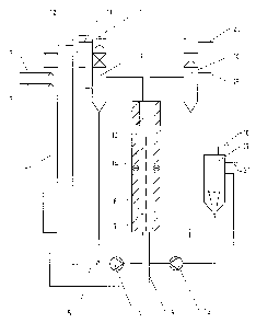
Figure 1 shows the flow diagram of an exemplary
electrolysis plant with preliminary reactor for the in-
situ preparation of sulfur dioxide and sodium sulfate
from bisulfate lye. In the preliminary reactor 1,
sulfuric acid is metered in at 2 and bisulfate lye is
metered in at 3 in a quantitative ratio such that, on
the one hand, the amount of sulfur dioxide consumed in
the process is formed and, on the other hand, the
sodium present is converted virtually completely into
sodiul'n sulfate. The virtually concentrated sodium
sulfate solution produced at the foot of the reactor i~
introduced, as indicated by 4, into the anolyte cycle,
and the sulfur dioxide emerging at the top of the
reactor is fed, indicated by 5, into the catholyte
cycle.
'
The catholyte is circulated using a circulation pump 6
through the cathode chambers 7 of the electrolysis cell
8 and the gas separator 9. At :LO, the amount of water
required to achieve the desired end concentration is
metered in to the catholyte cycle. At 11, the
separated-off anode gas escapes, and at l2 an amount of
a catholyte corresponding to t:he amount of liquid
introduced, enriched with sodium dithionite, passes
over. The cathode chamber is separated from the anode
CA 02345451 2001-07-31
- 9 -
chamber 14 by the ration exchanger membrane 13. The
anolyte is circulated using a circulation pump 15 via
the anode chambers and the gas separator 16 and the
dissolution vessel 17. In the dissolution vessel,
crystalline sodium sulfate is added at 18 to saturate
the anolyte. At 19 the potential-increasing
electrolysis additive is metered in, and at 20 the
separated-off anode gas emerges. The sodium
peroxodisulfate solution formed discharges from the
overflow of the dissolution vessel 21.
CA 02345451 2001-07-31
- 10 -
Example 2:
The small-pilot-scale experimental plant of
Example 1 was modified by omitting the preliminary
reactor. Anolyte and catholyte were circulated through
the electrode chambers of the electrolysis cell and
through the gas separators. The anolyte cycle
additionally included the sodium sulfate dissolving
vessel depicted in Fig. 1. A metering pump was used to
meter deionized water containing an addition of sodium
thiocyanate (as potential-increasing additive) into the
anolyte cycle. In addition, solid anhydrous sodium
sulfate was metered into the dissolving vessel. The
catholyte cycle was fed with gaseous sulfur dioxide
from a gas cylinder and with a sodium sulfite solution
by means of a metering pump. The sodium sulfite served
to make good a deficiency of sodium compounds in the
cathode chamber due to the reduced transfer of sodium
ions from the anode chamber into the cathode chamber.
The sulfur dioxide was metered in to regulate the pH to
about 5.8. This provided for optimum adjustment of the
SOz feed rate to the sodium ion transfer rate.
The electrolysis cell used was a bipolar filter
press electrolysis cell as used for peroxodisulfate
ether production and as described in DE 44 196 83. It
consisted of a clamping frame holding three electrode
plates, namely two edge plates with current supply and
a bipolar electrode plate in the middle. 'This
accordingly constituted two electrolysis cells, which
were connected in series :in electrical terms and were
connected in parallel with regard to the electrolyte
flows. The electrode plates consisted of impregnated
graphite with :integrated cooling channels and
incorporated inlets and outlets for the electrolyte
solutions and cooling water. Mounted on the anode side
were insulating plates composed of PVC and sealing
frames composed of EPDM about 3 mm in thickness. The
anodes were platinum foil strips disposed transversely
on the insulating plate and in contact with the
graphite supports laterally underneath the sealing
CA 02345451 2001-07-31
- 11 -
frames. The two electrode chambers were separated by
cation exchanger membranes cf the type Nafion 450
(DuPont). The cathode chambers were incorporated into
the supports in the form of parallel flow channels
(4 mm deep). Since the cell had a height of 2 000 mm,
the flow cross-secr_ions of the anode chambers and
cathode chambers were kept very small at about 1.5 cm2,
whereby high flow velocities were achievable along both
electrodes. The volume of liquid in tha cathode cycle
was minimized to be able to realize very short
residence times.
The following important technical data were
adhered to:
Anode area (platinum) 300 cm2 per electrode plate,
for a total of 600 cm2
Cathode area (graphite) 1 200 cmz per electrode plate,
for a total of 2 400 cmz
Current strength 2 x 150 A = 300 A current
capacity
Current densities: Anode 0.5 A/cmz,
cathode 0.12 A/cmz
Volume of catholyte cycle: 2.5 1
Volume of anolyte cycle
with dissolving vessel: 6.5 1
Circulating volume of
w anolyte=catholyte 400 1/h
Velocity along electrode
surfaces about 0.4 m/s
Number of circulations per
hour: Catholyte 160, anolyte 61.5
The following amounts were
metered:
Catholyte: 4.6 1/h of a solution with
95 g/1 Na2S03
Gas in: about 680 g/h SOZ (time-
based average)
Anolyte: 3.6 1/h water with
0.15 g/1 NaSCN
Dissolving vessel: 2 000 g/h Na2S04
CA 02345451 2001-07-31
- 12 -
The cooling of the cathode was adjusted so that
the temperature in t:he circulating catholyte was about
35°C and the anolyte came to a temperature of about
48°C. The cell voltage was 5.5 V (total voltage 11 V).
Following a start-up phase of about 6 h, a
steady state was reached, at which point the following
electrolyte quantities having the reported compositions
were removed via the overflows at the electrolyte
cycles under steady state conditions:
Anolyte: 4.1 1/h with 229 g/1 NazS208 + 215 g/1 Na2S04 +
8 g/1 HzS04.
The average residence time for the anolyte
cycle was about 95 min. The total yield of sodium
peroxodisulfate was 939 g/h, which corresponds to ;a
current yield of 70.5%.
Catholyte: 5.4 1/h with the
following composition: 142 g/1 NazSz04
ca. 70 g/1 Na2HS03
ca. 20 g/1 Na2S03
ca . 10 g/1 Na2S203
The average residence time for the catholyte
cycle was about 28 min. The total yield of sodium
dithionite was 767 g/h, which corresponds to a current
yield of 78.7%.