Language selection

Search

Patent 2345575 Summary

Third-party information liability

Some of the information on this Web page has been provided by external sources. The Government of Canada is not responsible for the accuracy, reliability or currency of the information supplied by external sources. Users wishing to rely upon this information should consult directly with the source of the information. Content provided by external sources is not subject to official languages, privacy and accessibility requirements.

Claims and Abstract availability

Any discrepancies in the text and image of the Claims and Abstract are due to differing posting times. Text of the Claims and Abstract are posted:

  • At the time the application is open to public inspection;
  • At the time of issue of the patent (grant).
(12) Patent: (11) CA 2345575
(54) English Title: THREAD COUPLING FOR A DRILL STRING FOR PERCUSSIVE ROCK DRILLING
(54) French Title: TRAIN DE TIGES A RACCORDS FILETES POUR PERCAGE A PERCUSSION DANS LA ROCHE
Status: Expired
Bibliographic Data
(51) International Patent Classification (IPC):
  • E21B 17/042 (2006.01)
  • F16L 15/06 (2006.01)
(72) Inventors :
  • SANDSTROM, ROGER (Sweden)
(73) Owners :
  • EPIROC DRILLING TOOLS AKTIEBOLAG (Not Available)
(71) Applicants :
  • UNIROC AB (Sweden)
(74) Agent: SMART & BIGGAR IP AGENCY CO.
(74) Associate agent:
(45) Issued: 2007-05-15
(86) PCT Filing Date: 1999-09-22
(87) Open to Public Inspection: 2000-04-06
Examination requested: 2004-01-14
Availability of licence: N/A
(25) Language of filing: English

Patent Cooperation Treaty (PCT): Yes
(86) PCT Filing Number: PCT/SE1999/001652
(87) International Publication Number: WO2000/019056
(85) National Entry: 2001-03-27

(30) Application Priority Data:
Application No. Country/Territory Date
9803267-5 Sweden 1998-09-28

Abstracts

English Abstract


Thread coupling for a drill string for percussive drilling. The thread
coupling is provided with a male thread (5) and a female thread
(4) cooperating therewith. The male thread is arranged on a first drill string
element (3) provided with a first impact surface (6). The
female thread is arranged on a second drill string element (2) which is
provided with a second impact surface (7). The threads are conical.
Furthermore the crests (8) of the male thread (5) have a radius of curvature
which is more than 30 % of the pitch of the thread.


French Abstract

Cette invention concerne un raccord fileté pour train de tiges utilisé dans le perçage à percussion. Ce raccord fileté comporte une filetage mâle (5) et un filetage femelle (4) correspondant. Le filetage mâle se trouve sur un premier élément de tige (3) présentant une première surface d'impact (6), et le filetage femelle sur un second élément de tige (2) présentant une seconde surface d'impact (7). Les filetages sont du type conique. Par ailleurs, les crêtes (8) du filet mâle (5) présentent un rayon de courbure qui dépasse les 30 % du pas du filet.

Claims

Note: Claims are shown in the official language in which they were submitted.


3

Claim:


1. Thread coupling for a drill string for percussive rock drilling comprising
a
male thread (5) and a female thread (4) cooperating therewith, said male
thread being
arranged on a first drill string element (3) and said female thread being
arranged on a
second drill string element (2), that said first drill string element (3) has
a first impact
surface (6) and that said second drill string element (2) has a second impact
surface (7),
said first and second impact surfaces being arranged to abut against each
other,
characterized in that said male thread (5) and said female thread (6) are
conical and
that the crests (8) of said male thread (5) have a radius of curvature which
is larger than
30% of the pitch of the thread.


Description

Note: Descriptions are shown in the official language in which they were submitted.


CA 02345575 2001-03-27

WO 00/19056 PCT/SE99/01652
Thread coupling for a drill stringfor percussive rock drilling

The present invention relates to a thread coupling for a drill string for
percussive rock
drilling.

In previously known thread couplings for percussive rock drilling one
sometimes obtains
breakage of the drill rod adjacent to the drill bit and on the skirt of the
drill bit adjacent to
the inner end of the thread of the drill bit. These breakages occur in
particular when the
collaring conditions are bad. The cause of these breakages is that the drill
rod adjacent to
its end surface in contact with a bottom impact surface on the drill bit is
prestressed by the
deformations occuring at the shock wave passage through the thread coupling in
combination with the applied torque. A corresponding prestressing is obtained
in the skirt
of the drill bit.

The present invention, which is defined in the subsequent claim, aims at
achieving a thread
coupling which avoids these breakages through forming the thread coupling such
that the
material thickness becomes optimal at those parts on drill rod and drill bit
which are most
sens'itive to breakage. This is achieved by means of a combination of conical
threads and a
well rounded crest of the threads. It has turned out to be advantageous to
have a radius of
curvature at the crest of the thread on the male thread which is at least 30%
of the pitch of
the thread. The conical thread form means that the prestressing of the thread
is moved away
from the contact surface between the end surface of the drill rod and the
bottom impact
surface. This effect is achieved because the pitch angle of the thread is
larger at smaller
thread diameter than at larger thread diameter, constant pitch.

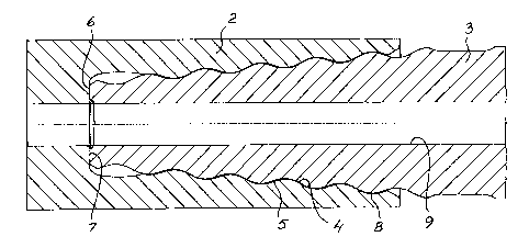
An embodiment of the invention is described below with reference to the
accompanying
drawing in which fig 1 shows a drill string with a thread coupling according
to the
invention. Fig 2 is a section through a thread coupling according to the
invention.

The drill string shown in the drawing comprises a drill bit 1, a drill rod 2
and a shank
adapter 3. Instead of a drill rod as shown one can have several. Drill bit,
drill rod and shank
adapter are drill string elements. The thread coupling shown in the drawing
comprises a


CA 02345575 2001-03-27

WO 00/19056 PCT/SE99/01652
2

male thread 5 arranged on a first drill string element 3 and a female thread 4
arranged on a
second drill string element 2. The first drill string element 3 is provided
with a first impact
surface 6. The second drill string element 2 is provided with a second impact
surface 7. In
the shown example contact is obtained between the impact surfaces 6,7 at the
bottom of the
female thread. One can alternatively form the drill string element such that
one obtains
contact at the outer end of the female thread. In this case the drill string
element with the
male thread is provided with an impact surface at the end of the male thread
which is
farthest away fzom the end of the drill string element. The drill string
elements are provided
with a central flushing channel 9. The male thread 5 and the female thread 4
are conical
with constant pitch. It has turned out to be advantageous to make the thread
with a cone
angle which is smaller than 20 . This means that the pitch angle of the
threads increases
when the diameter decreases. Through this the largest load on the threads is
moved away
from the area where known technique has had a tendency to give thread
breakage. Since the
crests 8 of the male threads 5 have been given a radius of curvature which is
more than
30% of the pitch of the thread good transfer of shock wave energy is obtained
without
overloading of the thread coupling.

Representative Drawing
A single figure which represents the drawing illustrating the invention.
Administrative Status

For a clearer understanding of the status of the application/patent presented on this page, the site Disclaimer , as well as the definitions for Patent , Administrative Status , Maintenance Fee  and Payment History  should be consulted.

Administrative Status

Title Date
Forecasted Issue Date 2007-05-15
(86) PCT Filing Date 1999-09-22
(87) PCT Publication Date 2000-04-06
(85) National Entry 2001-03-27
Examination Requested 2004-01-14
(45) Issued 2007-05-15
Expired 2019-09-23

Abandonment History

There is no abandonment history.

Payment History

Fee Type Anniversary Year Due Date Amount Paid Paid Date
Application Fee $300.00 2001-03-27
Registration of a document - section 124 $100.00 2001-05-02
Maintenance Fee - Application - New Act 2 2001-09-24 $100.00 2001-08-03
Maintenance Fee - Application - New Act 3 2002-09-23 $100.00 2002-08-06
Maintenance Fee - Application - New Act 4 2003-09-22 $100.00 2003-08-07
Request for Examination $800.00 2004-01-14
Maintenance Fee - Application - New Act 5 2004-09-22 $200.00 2004-08-05
Maintenance Fee - Application - New Act 6 2005-09-22 $200.00 2005-08-04
Maintenance Fee - Application - New Act 7 2006-09-22 $200.00 2006-08-04
Final Fee $300.00 2007-03-02
Maintenance Fee - Patent - New Act 8 2007-09-24 $200.00 2007-08-08
Maintenance Fee - Patent - New Act 9 2008-09-22 $200.00 2008-08-11
Maintenance Fee - Patent - New Act 10 2009-09-22 $250.00 2009-08-13
Maintenance Fee - Patent - New Act 11 2010-09-22 $250.00 2010-08-23
Maintenance Fee - Patent - New Act 12 2011-09-22 $250.00 2011-09-06
Maintenance Fee - Patent - New Act 13 2012-09-24 $250.00 2012-08-08
Maintenance Fee - Patent - New Act 14 2013-09-23 $250.00 2013-08-14
Maintenance Fee - Patent - New Act 15 2014-09-22 $450.00 2014-09-15
Maintenance Fee - Patent - New Act 16 2015-09-22 $450.00 2015-09-21
Maintenance Fee - Patent - New Act 17 2016-09-22 $450.00 2016-09-19
Maintenance Fee - Patent - New Act 18 2017-09-22 $450.00 2017-09-18
Registration of a document - section 124 $100.00 2018-01-19
Maintenance Fee - Patent - New Act 19 2018-09-24 $450.00 2018-09-17
Owners on Record

Note: Records showing the ownership history in alphabetical order.

Current Owners on Record
EPIROC DRILLING TOOLS AKTIEBOLAG
Past Owners on Record
ATLAS COPCO SECOROC AB
SANDSTROM, ROGER
UNIROC AB
Past Owners that do not appear in the "Owners on Record" listing will appear in other documentation within the application.
Documents

To view selected files, please enter reCAPTCHA code :


To view images, click a link in the Document Description column. To download the documents, select one or more checkboxes in the first column and then click the "Download Selected in PDF format (Zip Archive)" or the "Download Selected as Single PDF" button.

List of published and non-published patent-specific documents on the CPD .

If you have any difficulty accessing content, you can call the Client Service Centre at 1-866-997-1936 or send them an e-mail at CIPO Client Service Centre.


Document
Description 
Date
(yyyy-mm-dd) 
Number of pages   Size of Image (KB) 
Abstract 2001-03-27 1 58
Description 2001-03-27 2 86
Drawings 2001-03-27 1 29
Representative Drawing 2001-06-14 1 13
Claims 2001-03-27 1 20
Cover Page 2001-06-14 1 37
Representative Drawing 2007-04-27 1 14
Cover Page 2007-04-27 1 45
Prosecution-Amendment 2004-01-14 1 39
Assignment 2001-03-27 2 83
PCT 2001-03-27 7 270
Assignment 2001-05-02 2 75
Correspondence 2001-09-10 3 98
Correspondence 2007-03-02 1 36