Note: Descriptions are shown in the official language in which they were submitted.
CA 02345856 2001-07-04
LITHOGRAPHIC IMAGING WITH METAL-BASED,
NON-ABLATIVE WET PRINTING MEMBERS
FIELD OF THE INVENTION
The present invention relates to digital printing apparatus and methods, and
more particularly to imaging of lithographic printing-plate constructions on-
or off-
press using digitally controlled laser output.
BACKGROUND OF THE INVENTION
In offset lithography, a printable image is present on a printing member as a
pattern of ink-accepting (oleophilic) and ink-rejecting (oleophobic) surface
areas.
Once applied to these areas, ink can be efficiently transferred to a recording
medium in the irnagewise pattern with substantial fidelity. Dry printing
systems
utilize printing members whose ink-repellent portions are sufficiently phobic
to ink
as to permit its direct application. Ink applied uniformly to the printing
member is
transferred to the recording medium only in the imagewise pattern. Typically,
the
printing member first makes contact with a compliant intermediate surface
called a
blanket cylinder which, in turn, applies the image to the paper or other
recording
medium. In typical sheet-fed press systems, the recording medium is pinned to
an
impression cylinder, which brings it into contact with the blanket cylinder.
In a wet lithographic system, the non-image areas are hydrophilic, and the
necessary ink-repellency is provided by an initial application of a dampening
fluid to
109144-8
CA 02345856 2001-07-04
the plate prior to inking. The dampening fluid prevents ink from adhering to
the
non-image areas, but does not affect the oleophilic character of the image
areas.
To circumvent the cumbersome photographic development, plate-mounting
and plate-registration operations that typify traditional printing
technologies,
practitioners have developed electronic alternatives that store the imagewise
pattern in digital form and impress the pattern directly onto the plate. Plate-
imaging
devices amenable to computer control include various forms of lasers.
For example, U.S. Patent No. 5,493,971 discloses wet-plate constructions
that extend the benefits of ablative laser imaging technology to traditional
metal-
1o based plates. Such plates remain the standard for most of the long-run
printing
industry due to their durability and ease of manufacture. As shown in FIG. 1,
a
lithographic printing construction 100 in accordance with the '971 patent
includes
a grained-metal substrate 102, a protective layer 104 that can also serve as
an
adhesion-promoting primer, and an ablatable oleophilic surface layer 106. In
operation, imagewise pulses from an imaging laser (typically emitting in the
near-
infrared, or "IR" spectral region) interact with the surface layer 106,
causing
ablation thereof and, probably, inflicting some damage to the underlying
protective
layer 104 as well. The imaged plate 100 may then be subjected to a solvent
that
eliminates the exposed protective layer 104, but which does no damage either
to
2o the surface layer 106 or the unexposed protective layer 104 lying
thereunder. By
using the laser to directly reveal only the protective layer and not the
hydrophilic
109144-8 3
CA 02345856 2001-07-04
metal layer, the surface structure of the latter is fully preserved; the
action of the
solvent does no damage to this structure.
A related approach is disclosed in published PCT Application Nos.
US99/01321 and US99/01396. A printing member in accordance with this
approach, representatively illustrated at 200 in FIG. 2, has a grained metal
substrate 202, a hydrophilic layer 204 thereover, an ablatable layer 206, and
an
oleophilic surface layer 208. Surface layer 208 is transparent to imaging
radiation,
which is concentrated in layer 206 by virtue of that layer's intrinsic
absorption
characteristics and also due to layer 204, which provides a thermal barrier
that
1 o prevents heat loss into substrate 202. As the plate is imaged, ablation
debris is
confined beneath surface layer 208; and following imaging, those portions of
surface layer 208 overlying imaged regions are readily removed. Because layer
204
is hydrophilic and survives the imaging process, it can serve the printing
function
normally performed by grained aluminum, namely, adsorption of fountain
solution.
Both of these constructions rely on removal of the energy-absorbing layer to
create an image feature. Exposure to laser radiation may, for example, cause
ablation-i.e., catastrophic overheating-of the ablated layer in order to
facilitate its
removal. Accordingly, the laser pulse must transfer substantial energy to the
absorbing layer. This means that even low-power lasers must be capable of very
rapid response times, and imaging speeds (i.e., the laser pulse rate) must not
be so
fast as to preclude the requisite energy delivery by each imaging pulse.
109144-8 4
CA 02345856 2005-O1-06
Brief Summary of the Invention
In accordance with an aspect of the present invention there is provided a
method of imaging a lithographic printing member, the method comprising the
steps
of a. providing a printing member having a hydrophilic metal substrate and,
thereover, first and second layers, wherein (i) the first layer has a
thickness and a top
surface and comprises a material that absorbs imaging radiation, the absorbing
material being distributed in a concentration gradient from the exposed
surface
through the thickness of the first layer, and (ii) the second layer overlies
the first layer
1o and is oleophilic and substantially transparent to imaging radiation; b.
selectively
exposing the printing member to laser radiation in an imagewise pattern, laser
energy
being absorbed by the first layer where so exposed so as to heat the first
layer and
thereby irreversibly detach it from the substrate without substantial
ablation; and c.
removing remnants of the first and second layers where the sprinting member
received
15 radiation, thereby creating an irnagewise lithographic pattern on the
printing member.
In accordance with another aspect of the present invention there is provided a
lithographic printing member comprising a hydrophilic metal substrate and,
thereover,
first and second layers, wherein (i) the first layer has a thickness and a top
surface and
comprises a material that absorbs imaging radiation, the absorbing material
being
2o distributed in a concentration gradient from the exposed suri:ace through
the thickness
of the first layer, and (ii) the second layer overlies the first layer and is
oleophilic and
substantially transparent to imaging radiation, exposure to imaging radiation
causing
CA 02345856 2005-O1-06
the first layer and the substrate to irreversibly detach without substantial
ablation,
thereby facilitating removal, by subjection to the cleaning liquid, of the
first and
second layers where detachment has taken place.
In accordance with yet another aspect of the present invention there is
provided a method of imaging a lithographic printing member, the method
comprising
the steps of a. providing a printing member having a hydrophilic metal
substrate and,
thereover, first and second layers, wherein (i) the first layer has a
thickness and a top
surface and comprises a material that absorbs imaging radiation, and (ii) the
second
layer overlies the first layer and is oleophilic and substantially transparent
to imaging
l0 radiation; b. selectively exposing the printing member to laser radiation
in an
imagewise pattern, laser energy being absorbed by the first layer where so
exposed so
as to heat the first layer and cause formation of an interior split within the
thickness
thereof without substantially ablating the first layer; and c. removing
remnants of the
second layer and the first layer above the interior split where the printing
member
15 received radiation, thereby creating an imagewise lithograplhic pattern on
the printing
member.
In accordance with yet another aspect of the present invention there is
provided a
lithographic printing member comprising a hydrophilic metal substrate and,
thereover,
first and second layers, wherein (i) the first layer has a thickness and a top
surface and
20 comprises a material that absorbs imaging radiation, (ii) and the second
layer overlies
the first layer and is oleophilic and substantially transparent to imaging
radiation,
exposure to imaging radiation causing formation of an interiior split within
the
thickness of the first layer without substantially ablating the first layer,
thereby
5a
CA 02345856 2005-O1-06
facilitating removal, by subjection to the cleaning liquid, of the second
layer and the
first layer above the interior split.
The present invention obviates the need for substantial ablation as an imaging
mechanism, combining the benefits of simple construction, the ability to
utilize
traditional metal base supports, and amenability to imaging; with low-power
lasers that
need not impart ablation-inducing energy levels. In preferred embodiments, the
printing member having a topmost layer that is ink-receptive and a hydrophilic
metal
substrate. The topmost layer does not significantly absorb imaging radiation,
but an
intermediate layer disposed between the topmost layer and the metal substrate
does
1o absorb imaging radiation. In one version, in response to an imaging pulse,
the
absorbing layer debonds from the surface of the adjacent metal substrate; in
another
version, an interior split is formed within the absorbing layer, facilitating
removal of
the portion of that layer above the split. In neither case does the absorbing
layer
undergo substantial ablation.
It must be stressed that it is ordinarily impractical or even impossible to
image,
by ablation, constructions in which an absorbing layer directly overlies the
metal
substrate. This is because the thick metal substrate acts as a heat sink,
drawing laser
energy needed to heat the absorbing layer to achieve imaging. because
substantial
ablation is not involved as an imaging mechanism in embodiments of the present
2o invention, however, this condition is avoided. Sufficient energy is
concentrated
Sb
CA 02345856 2005-O1-06
in the upper portions of the absorbing-layer thickness to cause debonding
notwithstanding heat transport into the metal substrate. It is also possible
to create an
absorber gradient within the absorbing layer, with the absorber concentration
diminishing from the top of the layer to the bottom, so that the surface in
contact with
the metal substrate has very little absorber. This concentration gradient
further
discourages transfer of heat to the metal substrate while preserving
sufficient overall
absorption and heating to effect interfacial debonding. Indeed, some transfer
of heat to
the metal substrate (as well as to an overlying layer, when x>resent) is
desirable to
avoid unintended ablation of the absorbing layer, which can result in
production of
l0 unwanted volatile debris.
In use, the printing member is selectively exposed t:o laser radiation in an
imagewise pattern. Where the printing member has received laser exposure -
that is,
where the substrate and absorbing layer have been detached from each other -
remnants of the absorbing layer and the overlying layer (or layers) is readily
removed
by post-imaging cleaning (see, e.g., U.S. Patent Nos. 5,540,150; 5,870,954;
5,755,158; and 5,148,746) to produce a finished printing plate.
Accordingly, layers that would otherwise undergo complete destruction as a
consequence of ablation imaging are retained in the present constructions, and
serve
as highly durable layers that participate in the printing procf;ss.
Irreversible
2o detachment between layers is caused by heating, without substantial
ablation, of a
radiation-absorptive layer, and the absorber concentration gradient prevents
excessive
energy dissipation from the absorbing layer.
6
CA 02345856 2005-O1-06
The plates are "positive-working" in the sense that inherently ink-receptive
areas receive laser output and are ultimately removed, revealing the
hydrophilic layer
that will reject ink during printing; in other words, the "image area" is
selectively
removed to reveal the "background." Such plates are also referred to as
"indirect-
write."
It should be noted that, as used herein, the term "plate" or "member" refers
to
any type of printing member or surface capable of recordinsu an image defined
by
regions exhibiting differential affinities for ink and/or fountain solution;
suitable
to configurations include the traditional planar or curved lithographic plates
that are
mounted on the plate cylinder of a printing press, but can also include
seamless
cylinders (e.g., the roll surface of a plate cylinder), an endless belt, or
other
arrangement.
Furthermore, the term "hydrophilic" is used in the printing sense to connote a
surface affinity for a fluid which prevents ink from adhering thereto. Such
fluids
include water for conventional ink systems, aqueous and non-aqueous dampening
liquids, and the non-ink phase of single-fluid ink systems. fhus, a
hydrophilic surface
in accordance herewith exhibits preferential affinity for any of these
materials relative
to oil-based materials.
7
CA 02345856 2001-07-04
Brief Description of the Drawings
The foregoing discussion will be understood more readily from the following
detailed description of the invention, when taken in conjunction with the
accompanying drawings, in which:
FIGS. 1 and 2 are enlarged sectional views of prior-art printing members; and
FIG. 3 is an enlarged sectional view of a positive-working lithographic
printing member having a uniform absorber concentration;
FIGS. 4A-4C are an enlarged sectional views of a positive-working, graded-
absorber lithographic printing member in the unimaged, imaged, and cleaned
1 o states, respectively; and
FIGS. 5A and 5B illustrate imaging of the printing member of FIG. 4A so as
to produce an interior split.
The drawings and elements thereof may not be drawn to scale.
Detailed Description of the Preferred Embodiments
Imaging apparatus suitable for use in conjunction with the present printing
members includes at least one laser device that emits in the region of maximum
plate responsiveness, i.e., whose ~.max closely approximates the wavelength
region
109144-8 8
CA 02345856 2005-O1-06
where the plate absorbs most strongly. Specifications for lasers that emit in
the near-
IR region are fully described in U.S. Patent Nos. Re. 35,51:2 and 5,385,092;
lasers
emitting in other regions of the electromagnetic spectrum are well-known to
those
skilled in the art.
Suitable imaging configurations are also set forth in detail in the '512 and
'092 patents. Briefly, laser output can be provided directly to the plate
surface via
lenses or other beam-guiding components, or transmitted to~ the surface of a
blank
printing plate from a remotely sited laser using a fiber-optic; cable. A
controller and
associated positioning hardware maintain the beam output at a precise
orientation
with respect to the plate surface, scan the output over the surface, and
activate the
laser at positions adjacent selected points or areas of the plate. The
controller
responds to incoming image signals corresponding to the original document or
picture
being copied onto the plate to produce a precise negative or positive image of
that
original. The image signals are stored as a bitmap data file on a computer.
Such files
may be generated by a raster image processor ("RIP") or other suitable means.
For
example, a RIP can accept input data in page-description lalzguage, which
defines all
of the features required to be transferred onto the printing plate, or as a
combination
of page-description language and one or more image data files. The bitmaps are
constructed to define the hue of the color as well as screen frequencies and
angles.
9
CA 02345856 2005-O1-06
Other imaging systems, such as those involving light valuing and similar
arrangements, can also be employed; see, e.g., U.S. Patent lVos. 4,577,932;
5,517,359;
5,802,034; and 5,861, 992. Moreover, it should also be noted that image spots
may be
applied in an adjacent or in an overlapping fashion.
The imaging apparatus can operate on its own, functioning solely as a
platemaker, or can be incorporated directly into a lithographic printing
press. In the
latter case, printing may commence immediately after application of the image
to a
blank plate, thereby reducing press set-up time considerably. The imaging
apparatus
can be configured as a flatbed recorder or as a drum recorder, with the
lithographic
to plate blank mounted to the interior or exterior cylindrical s~:~rface of
the drum.
Obviously, the exterior drum design is more appropriate to use in ,situ, on a
lithographic press, in which case the print cylinder itself constitutes the
drum
component of the recorder or plotter.
In the drum configuration, the requisite relative motion between the laser
beam and the plate is achieved by rotating the drum (and thf; plate mounted
thereon)
about its axis and moving the beam parallel to the rotation axis, thereby
scanning the
plate circumferentially so the image "grows" in the axial direction.
Alternatively, the
beam can move parallel to the drum axis and, after each pass across the plate,
increment angularly so that the image on the plate "grows" c;ircumferentially.
In both
2o cases, after a complete scan by the beam, an image
CA 02345856 2001-07-04
corresponding (positively or negatively) to the original document or picture
will have
been applied to the surface of the plate.
In the flatbed configuration, the beam is drawn across either axis of the
plate, and is indexed along the other axis after each pass. Of course, the
requisite
relative motion between the beam and the plate may be produced by movement of
the plate rather than (or in addition to) movement of the beam.
Regardless of the manner in which the beam is scanned, in an array-type
system it is generally preferable (for on-press applications) to employ a
plurality of
lasers and guide their outputs to a single writing array. The writing array is
then
indexed, after completion of each pass across or along the plate, a distance
determined by the number of beams emanating from the array, and by the desired
resolution (i.e., the number of image points per unit length). Off-press
applications,
which can be designed to accommodate very rapid scanning (e.g., through use of
high-speed motors, mirrors, etc.) and thereby utilize high laser pulse rates,
can
frequently utilize a single laser as an imaging source.
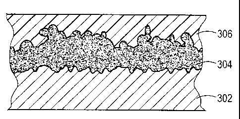
With reference to FIGS. 3 and 4A-4C, a representative embodiment of a
lithographic printing member in accordance herewith includes a metal substrate
302, a radiation-absorptive layer 304, and an oleophilic layer 306 that is
substantially transparent to imaging radiation. Layer 306 is optional,
however, and
2o the construction may be limited to a metal substrate 302 and an oleophilic,
radiation-absorptive layer 304.
109144-8 1 1
CA 02345856 2001-07-04
7. Substrate 302
The primary function of substrate 302 is to provide dimensionally stable
mechanical support, and possibly to dissipate heat accumulated in layer 304 to
prevent its ablation. Suitable substrate materials include, but are not
limited to,
alloys of aluminum and steel (which may have another metal such as copper
plated
over one surface). Preferred thicknesses range from 0.004 to 0.02 inch, with
thicknesses in the range 0.005 to 0.012 inch being particularly preferred.
Substrate 302 has a hydrophilic surface. In general, metal layers must
undergo special treatment in order to be capable of accepting fountain
solution in a
1o printing environment. Any number of chemical or electrical techniques, in
some
cases assisted by the use of fine abrasives to roughen the surface, may be
employed for this purpose. For example, electrograining involves immersion of
two
opposed aluminum plates (or one plate and a suitable counterelectrode) in an
electrolytic cell and passing alternating current between them. The result of
this
process is a finely pitted surface topography that readily adsorbs water. See,
e.g.,
U.S. Patent No. 4,087,341.
A structured or grained surface can also be produced by controlled oxidation,
a process commonly called "anodizing." An anodized aluminum substrate consists
of an unmodified base layer and a porous, "anodic" aluminum oxide coating
2o thereover; this coating readily accepts water. However, without further
treatment,
the oxide coating would lose wettability due to further chemical reaction.
Anodized
109144-8 12
CA 02345856 2001-07-04
plates are, therefore, typically exposed to a silicate solution or other
suitable (e.g.,
phosphate) reagent that stabilizes the hydrophilic character of the plate
surface. In
the case of silicate treatment, the surface may assume the properties of a
molecular sieve with a high affinity for molecules of a definite size and
shape-
including, most importantly, water molecules. The treated surface also
promotes
adhesion to an overlying photopolymer layer. Anodizing and silicate treatment
processes are described in U.S. Patent Nos. 3,181,461 and 3,902,976.
Preferred hydrophilic substrate materials include aluminum that has been
mechanically, chemically, and/or electrically grained with or without
subsequent
1o anodization. !n addition, some metal layers need only be cleaned, or
cleaned and
anodized, to present a sufficiently hydrophilic surface. A hydrophilic surface
is
easier to coat with layer 304, and provides better adhesion to that layer.
2. Layer 304
Layer 304 absorbs imaging radiation to cause irreversible detachment from
metal layer 302. The layer may contain a uniform dispersion of a radiation
absorber, as shown in FIG. 3, or a dispersion graded in concentration from the
top
to the bottom of its thickness as shown in FIG. 4A.
Preferred base materials for layer 304 are polymeric and capable of receiving
a radiation absorber (if desired, in a graded fashion). Accordingly, the
primary
2o considerations in choosing a material for layer 304 relate to fabrication
and
manufacturability. Formulations based on polyvinyl alcohol respond to solvents
or
109144-8 13
CA 02345856 2005-O1-06
saturants, which allow the absorber to penetrate the layer 304 even after it
has been
applied and cured. The degree of cross-linking within layer 304 rnay be
controlled in
order to enhance this property.
Thus, layer 304 may comprise a polymer and a crosslinking agent. Suitable
hydrophilic polymers for layer 304 include, but are not limited to, polyvinyl
alcohol
and cellulosics. In a preferred embodiment, the hydrophilic polymer is
polyvinyl
alcohol. In one version thereof, the crosslinking agent is a zirconium
compound,
preferably ammonium zirconyl carbonate. Suitable polyvinyl alcohol-based
coatings
for use in connection with this layer include, but are not limited to,
combinations of
1o AIRVOLTM 325 polyvinyl alcohol; BACOTETMTM 20, an ammonium zirconyl
carbonate solution available from Magnesium Elektron, Flemington, NJ, in
combination with additives such as humectants to modify the rewettability of
the
coating following application. Suitable additives include glycerol;
pentaerythritol;
glycols such as ethylene glycol, diethylene glycol, trimeth.ylene diglycol,
and
propylene glycol; citric acid, glycerophosphoric acid; sorbitol; gluconic
acid; and
TRITONTTM X-100, a surfactant available from Rohm & Haas, Philadelphia, PA.
Typical amounts of BACOTE 20 utilized in crosslinking polymers are less than 5
wt% of the weight of the polymers, as described, for example, in "The Use of
Zirconium in Surface Coatings," Application Information Sheet 117
(Provisional), by
2o P.J. Moles, Magnesium Electron, Inc., Flemington, NJ. Surprisingly, it has
been found
that significantly increased levels of BACOTE 20, such as 40 wt% of the
polyvinyl
alcohol polymer, provide significant improvements in the ease of cleaning the
laser-
14
CA 02345856 2001-07-04
exposed areas, in the durability and adhesion during long press runs, and in
the fine
image resolution and printing quality that can be achieved. The high levels of
BACOTE 20 also provide a layer 304 that interacts with a subsequent coating
application of an overlying layer 306 (or a primer layer) as discussed below.
In one
embodiment, layer 304 comprises ammonium zirconyl carbonate in an amount
greater than 10 wt% based on the total weight of the polymers present in the
hydrophilic third layer. Zirconyl carbonate may, for example, be present in an
amount of 5 to 100 wt% based on the total weight of polymers present in layer
304.
1o Other suitable coatings include copolymers of polyvinyl alcohol with
polyvinyl
pyrrolidone (PVP), and copolymers of polyvinylether (PVE) including
polyvinylether/maleic anhydride versions.
Layer 304 is coated in this invention typically at a thickness in the range of
from about 1 to about 40 ~m and more preferably in the range of from about 1
to
about 5 pm. After coating, the layer is dried and subsequently cured at a
temperature between 135 °C and 185 °C for between 10 sec and 3
min and more
preferably at a temperature between 145 °C and 165 °C for
between 30 sec and 2
min.
For uniform absorber distributions, the absorber is introduced and dispersed
2o into the polymer or polymer precursor prior to curing. By contrast, to
achieve a
graded concentration, the absorber is typically introduced into layer 304
after the
109144-8 15
CA 02345856 2001-07-04
latter is cured. Essentially, the absorber is dissolved or dispersed within a
carrier
that will uniformly wet the surface of layer 304. The absorber mixture, which
may
also contain wetting and/or leveling agents, is coated onto the exposed
surface of
layer 304 and allowed to impregnate the layer. The cross-linking of layer 304
acts
as an imperfect barrier to penetration that creates a concentration gradient
in which
the absorber concentrated toward the upper portion of the layer. A porous
polymeric structure, such as that obtained with the zirconia-filled BACOTE 20
material, is desirable in this regard. It should be emphasized that the
applied
absorber becomes part of layer 304 (its concentration decreasing with depth),
and
1o does not persist as a separate layer.
In the case of IR or near-IR imaging radiation, suitable absorbers include a
wide range of dyes and pigments, such as carbon black; nigrosine-based dyes;
phthalocyanines (e.g., aluminum phthalocyanine chloride, titanium oxide
phthalocyanine, vanadium (IV) oxide phthalocyanine, and the soluble
phthalocyanines supplied by Aldrich Chemical Co., Milwaukee, WI);
naphthalocyanines (see, e.g., U.S. Patent Nos. 4,977,068; 4,997,744;
5,023,167;
5,047,312; 5,087,390; 5,064,951; 5,053,323; 4,723,525; 4,622,179;
4,492,750; and 4,622,179); iron chelates (see, e.g., U.S. Patent Nos.
4,912,083;
4,892,584; and 5,036,040); nickel chelates (see, e.g., U.S. Patent Nos.
5,024,923; 4,921;317; and 4,913,846); oxoindolizines (see, e.g., U.S. Patent
No.
4,446,223); iminium salts (see, e.g., U.S. Patent No. 5,108,873); and
indophenols
(see, e.g., U.S. Patent No. 4,923,638); TiON, TiCN, tungsten oxides of
chemical
109144-8 16
CA 02345856 2005-O1-06
formula 'VV03_X, where O < x < 0.5 (with 2.7 ~ ~.9 being preferred); and
vanadium
oxides of chemical formula V205_X, where O < x < 1.0 (mth V6O13 being
preferred).
Pigments are typically utilized in the form of aqueous or solvent dispersions.
The absorption sensitizer should minimally affect adhesion between layer 304
and any overlying layer (as discussed below). Surface-modified carbon-black
pigments sold under the trade designation CAB-O-JETTM 200 by Cabot
Corporation,
Bedford, MA are found to minimally disrupt adhesion at loading levels
providing
adequate sensitivity for heating. The CAB-O-JET series o~f carbon black
products are
unique aqueous pigment dispersions made with novel surface modification
to technology, as, for example, described in U.S. Patent Nos. 5,554,739 and
5,713,988.
Pigment stability is achieved through ionic stabilization. No surfactants,
dispersion
aids, or polymers are typically present in the dispersion of the CAB-O-JET
materials.
CAB-O-JET 200 is a black liquid, having a viscosity of less than about 10 cP
(Shell
#2 efflux cup); a pH of about 7; 20% (based on pigment) solids in water; a
stability
Z5 (i.e., no change in any physical property) of more than 3 freeze-thaw
cycles at -20°C,
greater than six weeks at 70 °C, and more than 2 yr at room
temperature; and a mean
particle size of 0.12 p.m, with 100% of the particles being less than 0.5 pm.
Significantly, CAB-O-JET 200 also absorbs across the entire infraxed spectrum,
as
well as across the visible and ultraviolet regions.
17
CA 02345856 2005-O1-06
BONJET BLACK CW-1TM, a surface-modified carbon-black aqueous dispersion
available from Orient Corporation, Springfield, NJ, also resulted in adhesion
to the
hydrophilic layer 304 at the amounts required to give adequate sensitivity for
ablation.
Other near-1R absorbers for absorbing layers based. on polyvinyl alcohol
include conductive polymers, e.g., polyanilines, polypyrrol.es, poly-3,4-
ethylenedioxypyrroles, polythiophenes, and poly-3,4-ethylenedioxythiophenes.
These
can be applied to layer 304 subsequent to the curing proce ss; see, e.g., U.S.
Patent No.
5.908,705. For conductive polymers based on polypyrroles, the catalyst for
polymerization conveniently provides the "dopant' that establishes
conductivity.
1o Suitable coatings may be formed by known mixing and coating methods, for
example, wherein a base coating mix is formed by first mixing the various
components, delaying the addition of cross-linking agents to the base coating
mix or
dispersion just prior to the coating application. The coating mix or
dispersion may be
applied by any of the known methods of coating application, such as, for
example,
wire-wound rod coating, reverse-roll coating, gravure coating, or slot-die
coating.
After drying to remove the volatile liquids, a solid coating layer is formed.
Exemplary saturating dispersions for impregnation into a suitable layer 304
are as follows.
18
CA 02345856 2005-O1-06
Colnpo~t EXSmpie 1 FxaI1?ple 2
(parts by weighty (P~gnre~nt (Dye Disp~er~orrl
Dispersion
BONJET Black CW-1 20.0 --
W ater 100.0 ~ --
TRITON X-100 0.2 --
Methyl ethyl ketone , 100.0
IR 810. 1.5
IR 810 refers to the IR-absorbing oxyindoliZine dye (= 810 nml described in
U.S. Patent No. 4,948,778:.
For each of Examples ) a~ 2, the formulation is ato a suitat3ie
coat~g~ such as the following ~sxemptary polyvinyl alcohol-based coating,
following
cure. The following coating is cured by dryir~ four 2 min at 300 °F.
.. ~:OrnPonea~ Example 3
(park: b1! w.
AIRVOL 125 9:0
1/1/at~r 187.8
BACDTE 20 3.0
TRITON X-100 0.2 r
'o As shown in FIGS. 4B and 4C, exposure of layer 304 to an imaging poise
(either directly or, as depicted, through a transparent layer 306) causes
layer 304
i 09144-a ' g
CA 02345856 2001-07-04
to irreversibly detach from the hydrophilic surface of substrate 302 (FIG.
3B). The
detched region may be removed by any suitable post-image cleaning process,
with
the result that the surface of layer 302 is exposed. Layer 304 (or, if used,
layer
306) is oleophilic, providing the necessary affinity difference to support
lithographic
printing.
Alternatively, as shown in FIGS. 5A and 5B, exposure of the printing member
to imaging radiation may create an interior split 310. This mechanism can be
advantageous in that, following cleaning, a remnant of layer 304 remains over
the
surface of substrate 302. That surface is typically vulnerable to
environmental
1o damage that decreases hydrophilic response, so that overlying remnant
affords
stabilization. So long as layer 304 is hydrophilic, it will function as the
lithographic
equivalent of the substrate surface (throughout the useful life of the
printing
member or until worn away to expose the substrate surface). Finally, if layer
304
is colored, the low absorber concentration at the bottom of the layer
thickness
allow this color to be observed. Where layer 304 has not received imaging
radiation, the color will be overwhelmed by the dark absorber concentrated at
the
top of the layer, resulting in useful contrast between imaged and unimaged
portions
of the printing member.
With reference to the alternative embodiment shown in FIG. 3, which utilizes
2o a uniform dispersion of absorber through layer 304, an exemplary
formulation is as
follows:
109144-8 20
CA 02345856 2001-07-04
Component Example 4
(parts by weightl
AIRVOI_ 125 8.5
Water 167.5
BACOTE 20 14.0
BONJET CW-1 40.0
TRITON X-100 0.2
The BACOTE 20 is utilized as supplied with 20% Zr02 content. A useful
application weight is 1.7 g/m2.
Key to the present invention is the resistance of layer 304 to reattachment to
substrate 302. Following separation, layer 304 and substrate 302 remain
separated, and layer 304-whether detached or internally split-does not undergo
substantial ablation. (By "substantial ablation" is meant destruction of 75%
or
more of the bulk of layer 304.)
Unlike ablation systems, in which the heating layer is destroyed by imaging
radiation, the present invention requires the heat accumulating in that layer
to
merely cause detachment from the underlying substrate. The heated layer
persists
following imaging and participates in the printing process.
In considering present approach against ablation-type systems, it should be
recognized that heating a multi-layer recording construction having a heat-
sensitive
layer can produce any of five results: ( 1 ) if insufficient heating energy is
applied,
the heated layer will be unaffected; (2) if the layers of the recording
material are
109144-8 21
CA 02345856 2001-07-04
not well-chosen, the heated layer may become hot, but may not cause interlayer
detachment; (3) if the layers of the recording material are not well-chosen,
the
heated layer may detach from the substrate, but it will then reattach; (4) if
the
layers of the recording material are properly chosen, the heated layer may
detach
from the substrate and remain detached; or (5) if a substantial quantity of
energy is
applied, the heat-sensitive layer may be ablated.
The present invention concerns only the fourth possibility. Accordingly, the
proper amount of energy must be delivered to cause the desired behavior. This,
in
turn, is a function of parameters such as laser power, the duration of the
pulse, the
1 o intrinsic absorption of the heat-sensitive layer (as determined, for
example, by the
concentration of absorber therein), the thickness of the heat-sensitive layer,
and the
presence of a thermally conductive layer beneath the heat-sensitive layer.
These
parameters are readily determined by the skilled practitioner without undue
experimentation. It is possible, for example, to cause the same materials to
undergo ablation or to simply become heated without damage.
3. Surface Layer 306
Layer 306 accepts ink and is substantially transparent to imaging radiation.
By "substantially transparent" is meant that the layer does not significantly
absorb
in the relevant spectral region, i.e., passes at least 90% of incident imaging
2o radiation. Important characteristics of ink-accepting surface layer 306
include
oleophilicity and hydrophobicity, resistance to solubilization by water and
solvents,
109144-8 2 2
CA 02345856 2005-O1-06
and durability when used on a printing press. Suitablle polymers utilized in
this Layer
should have excellent adhesion to layer 304 and highs wear resistance. They
can be
either water-based or solvent-based polymers. Any decomposition byproducts
produced by ink-accepting surface layer 306 should be environmentally and
toxicologically innocuous. This layer also may include a crosslinking agent
which
provides improved bonding to layer 304 and increased durability of the plate
for
extremely long print runs.
The following are working examples of layer 306:
Component Example 5 EXampIe 6 Example 7
(parts by weight) (S~H-Based) (Cxossainked (Colored)
Nit~rocellulosel
PS-120 10.0 - -
Heptane 189.8 -- --
PC-072 0.2 -
5-6 Sec RS nitrocellulose-- 10.0 10.0
CYMEL 303 TM -- 2.0 2.0
NACURE 2530TM -- 4.0 4.0
Methyl ethyl ketone - 148.0 146.5
N-propyl acetate -- 35.0 35.0
Victoria Blue BO - 1.5
1o PS-120 is a polymethylhydrosifoxane cross-linking agent and PC-072 is a
platinum-
divinyltetramethyldisitoxane catalyst, both marketed by Huls. NaCure 2530,
supplied by King Industries, Norwatk, CT, is an amine-blocked p-
toluenesulfonic
acid solution in an isopropanol/methanol blend.
109144-8 23 _
CA 02345856 2001-07-04
Any of the above coatings may be applied to a cured layer 304 (after any
absorber impregnation), following which it is then cured.
Example 5 is optimal for coating over uniform layer 304 as described in
Example 4. Cast and cured on this layer 304 or that described in Examples 1
/3,
the result is a black image on a light gray background (the color of the
lithographic
aluminum substrate 302). It is found that the layer 304 of Example 5 does not
interact well with the dye-based construction of Examples 2/3. Example 6 may
be
cast and cured on layer 304 in accordance with Examples 1/3, but produces a
light
olive green image on a light gray background that may be difficult to assess
for
1 o quality. Example 7, however, cast and cured on the formulation of Examples
1 /3
provides a bright blue image easily distinguished over a gray background.
Numerous variations on these approaches are possible. For example, using
lithographic aluminum as substrate 302, it is possible to apply, dry and cure
a
polyvinyl alcohoI/BACOTE 20 coating containing NACURE 2530. The result is a
hydrophilic coating containing free PTSA (p-toluene sulfonic acid); the amines
used
to neutralize the PTSA volatilize during drying and curing. A solution
containing
pyrrole monomer may be applied to the coating to impregnate it with an IR
absorber. The free PTSA provides a catalyst (and anion) for in situ
polypyrrole
formation. The result is a near-IR absorbing, conductive polymer formed within
the
2o polyvinyl alcohoI/BACOTE 20 layer.
109144-8 24
CA 02345856 2005-O1-06
One can then apply a durable; hydrophobic (oleophilie/melanophilic) overcoat
306 to provide an ink-receptive surface. Like the other printing members
described
above, the resulting plate is designed for positive imaging and conventional
printing
(dampening fluid) including single-fluid inks.
!t will therefore be seen that the foregoing techniques provide a basis for
improved Lithographic printing and superior plate con structions. The terms
and
expressions employed herein are used as terms of description and not of
limitation;
and there is no intention, in the use of such terms and expressions, of
excluding
any equivalents of the features shown and described or portions thereof, but
it is
o recognized that various modifications are possible within the scope of the
invention
claimed.
7 09144-8 25