Language selection

Search

Patent 2346323 Summary

Third-party information liability

Some of the information on this Web page has been provided by external sources. The Government of Canada is not responsible for the accuracy, reliability or currency of the information supplied by external sources. Users wishing to rely upon this information should consult directly with the source of the information. Content provided by external sources is not subject to official languages, privacy and accessibility requirements.

Claims and Abstract availability

Any discrepancies in the text and image of the Claims and Abstract are due to differing posting times. Text of the Claims and Abstract are posted:

  • At the time the application is open to public inspection;
  • At the time of issue of the patent (grant).
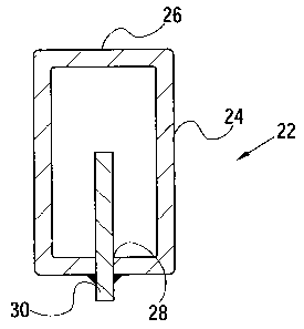
(12) Patent: (11) CA 2346323
(54) English Title: LOADER BOOM REINFORCEMENT
(54) French Title: RENFORT DE FLECHE DE CHARGEUR
Status: Expired and beyond the Period of Reversal
Bibliographic Data
(51) International Patent Classification (IPC):
  • E02F 9/14 (2006.01)
  • B23P 15/00 (2006.01)
  • E02F 3/34 (2006.01)
  • E02F 3/38 (2006.01)
(72) Inventors :
  • ESPANEL, CHRISTOPHE (France)
  • VITTET, CYRILLE (France)
(73) Owners :
  • DEERE & COMPANY
(71) Applicants :
  • DEERE & COMPANY (United States of America)
(74) Agent: BORDEN LADNER GERVAIS LLP
(74) Associate agent:
(45) Issued: 2005-04-19
(22) Filed Date: 2001-05-04
(41) Open to Public Inspection: 2001-11-05
Examination requested: 2001-05-04
Availability of licence: N/A
Dedicated to the Public: N/A
(25) Language of filing: English

Patent Cooperation Treaty (PCT): No

(30) Application Priority Data:
Application No. Country/Territory Date
100 22 021.5 (Germany) 2000-05-05

Abstracts

English Abstract


A loader boom has arms constructed as tubes that are rectangular in cross
section and taper from a bracket for mounting the arms to a tractor. The tubes
are
each formed by bending a blank of steel material so as to create four
90° corners
with opposite ends of the blank extending parallel to each other and forming a
gap
along, and in the center of, an under side of the tube. A reinforcing bar is
located in
the gap and secured to the tube by fillet welds.


Claims

Note: Claims are shown in the official language in which they were submitted.

CLAIMS:
1. In a loader boom for a front loader, wherein the boom includes tubular
arms, the improvement comprising: each arm having a narrow gap of
substantially
constant width extending lengthwise thereof; and an elongate bar being located
in
said gap and welded to said arm and forming a rib located within said arm.
2. The loader boom defined in claim 1 wherein a portion of said bar is
located exteriorly of said arm.
3. The loader boom defined in claim 1 wherein said arm is rectangular in
cross section with said gap being located in a narrow side of said arm.
4. The loader boom defined in claim 1 wherein said gap extends an entire
length of said arm.
5. The loader boom defined in claim 1 wherein said gap is located at an
underside of said arm and said bar having a height dimension extending
vertically
within said arm.
6. A method of making a reinforced tubular loader boom arm comprising
the steps of:
(a) sizing a sheet of metal stock material so as to produce a blank that it is
properly dimensioned to farm the desired tubular arm;
(b) bending said blank into a partial tube wherein opposite ends of said blank
are left disposed in confronting, parallel spaced relationship to each other
so as to
form a gap leading to an interior of said partial tube;
(c) inserting a bar into said gap so that it extends along and snugly engages
said opposite ends of said blank and extends a preselected distance into said
partial
tube so as to define a rib; and
(d) welding said bar to said partial tube.

Description

Note: Descriptions are shown in the official language in which they were submitted.


CA 02346323 2004-04-20
LOADER BOOM REINFORCEMENT
Field of the Invention
[0001] The present invention concerns a loader boom arm, especially an arm fur
a
front end loader wherein the arm is constructed so as to be in the form of a
tube.
Background of the Invention
(0002] Loaders are installed, for example, on farm tractors and are moveable
vertically for lifting loads. In the case of a front loader, the loader
includes a loader
boom having a forward end to which implements are attached, while the rear end
is
connected in an articulated manner to the farm tractor. Due to the length of
the
loader boom, and the forces involved, substantial bending moments arise in the
loader arms constituting the boom. Various measures have been attempted in the
known loader boom arms to make a basically square tube-like support that is
more
resistant to bending. For example, it is known to weld to U-channel sections
together to form a rectangular tube or to insert two squared sections that are
approximately 75% closed together and weld them in place to form a tube.
According to another known design, two hollow sections partially open on the
broad
side are placed on each other and welded together to form a closed tube
resistant to
bending.
(0003) The problem underlying the invention is that the known loader linkage
arms
are too expensive.
Summary of the Invention
(0004) According to the present invention, there is provided a loader boom arm
construction that represents a less expensive option to the aforementioned
known
designs.
(0005] An object of the invention is to provide a relatively inexpensive
loader boom
arm construction having a tubular configuration preferably defined by no more
than
two components with one of the components being simple bar.
(0006] A more specific object of the invention is to provide a loader boom arm
formed of a first component bent from a sheet of material, so as to form a
tube
having a slot at one side defined by parallel edges of said sheet material,
and a
second component in the form of a rectangular bar received in the slot defined
by the
first component and welded to the first component at locations extending along
the
opposite sides of the slot.
(0007] These and other objects will become apparent from a reading of the
ensuing

CA 02346323 2001-05-04
description together with the appended drawings.
Brief Description of the Drawings
[0008] FIG. 1 is a somewhat schematic left side view of a front end loader.
[0009] FIG. 2 is a vertical sectional view taken along line 2--2 of FIG. 1.
Description of the Preferred Embodiment
[0010] Referring now to the drawings, there is shown a loader 10 including a
loader boom 12, a mounting standard or bracket 14, hydraulic cylinders 16 and
an
implement 18, here shown as being a bucket. The loader 10 is shown disposed as
if
attached to a farm tractor, of which the only part shown is a portion of a
steerable
front wheel 20. The loader 10 is designed as a front loader that is used in
particular
in agriculture or in the municipal area and lifts loads up to approximately
1000 kgs.
[0011) The loader boom 12 extends between the bracket 14 and the implement 18
and has a bend of nearly 90 degrees. Due to the forces involved, the loader
boom is
formed of a pair of tubular boom arms 22 that are in the preferred embodiment,
broadened in a tapered fashion, in the plane of the drawing, up to the bend.
[0012] One mounting standard or bracket 14 is associated with each boom arm 22
and serves to connect the rear end of the associated arm to the farm tractor
for
pivoting vertically about a horizontal transverse axis.
[0013] The hydraulic cylinders 16 effect the vertical movement of the loader
boom
12 and are supported at one end on an associated one of the brackets 14 and at
the
other end on the associated one of the boom arms 22 in its vertically
pivotable
bending zone. The hydraulic cylinders 16 are coupled to a hydraulic system
located
on the tractor and are controlled in a known manner. Additional hydraulic
cylinders
are provided in a known manner between the loader linkage arm 12 and the
implement 18, but they are not considered further.
[0014] The loader arm 22 is depicted in detail in cross section in FIG. 2 and
includes opposite parallel walls 24 as high webs, narrow sides 26 as cross
webs, a
gap 28 and an inserted bar 30.
[0015] The loader arm 22 is designed as a tapered rectangular tube that is
formed
of an approximately 6-10 mm thick plate. The steel plate is stamped, cut, or
shaped
in another manner according to the developed view of the support arm 22 and
then
2

CA 02346323 2001-05-04
is correspondingly bent 90° in the same direction each time. The blank
of material is
sized and the bending is done so that the gap 28 remains defined between
spaced
parallel ends of the formed blank. While four right-angle bends are provided
in the
embodiment shown, a round, pentagonal, hexagonal, or other tube cross-section
could also be provided. The position shown in FIG. 2 matches the actual
positional
situation.
[0016] At any given section along the length of the arm 22, the walls 24 are
parallel
to each other as are the narrow walls 26, with the walls meeting so as to form
right
angled corners. The lower wall 26 could be called an interrupted narrow side
inas-
much as it is interrupted by the gap 28. However, considering the whole length
of
the arm 22 between the standard 14 and the bend, the walls 24 increase in
height
from the standard 14 while the upper and lower walls 26 diverge from each
other.
[0017] The width of the gap 28 corresponds essentially to the width of the bar
30. If
a clearance fit is selected, the bar 30 can be easily shoved into the gap 28
and be
held by means of an appliance until it is welded to the opposite parts of the
lower
narrow side 26. Instead of such a holding appliance, the walls 24 could be
pressed
towards each other to hold the bar 30 between them by friction. In the case of
a
press fit between the gap 28 and the bar 30, the gap 28 is first opened
somewhat ,
the bar 30 inserted, then the wall portions at the opposite sides of the bar
30
released so as to press against the bar 30. Alternatively, the widening can be
simply achieved by slightly chamfering the end of the bar 30 entering through
the
gap 28 into the interior of the arm 22, in which case the bar is forced
sufficiently to
overcome the squeezing force of the interrupted lower wall 26.
[0018] The bar 30 is formed from flat steel and is uniformly rectangular. In
the
embodiment shown, the bar 30 projects beyond approximately half the height of
the
interior while on the other hand it projects beyond the outer surface of the
arm 22 by
approximately one-sixth. If the bending forces to be withstood so dictate, the
bar 30
can also extend across the entire interior of the support tube 22 as well as
beyond
on beyond its outer surface. The bar 30 is welded to the interrupted lower
wall 26 at
the sides of the gap 28 by fillet welds. If the walls 24 are tapered while the
bar 30 is
square or rectangular, the region of the bar 30 that projects beyond the arm
22 on
3

CA 02346323 2001-05-04
the outside assumes a wedge-shaped form.
[0019] In the embodiment shown, the bar 30 extends only in the region of the
support tube 22 between the bend and the bracket 14. Notwithstanding, another
similar bar can be provided in the region between the bend and the implement
18.
Other than as shown, the bar 30 can also extend through the upper narrow side
26.
[0020] Having described the preferred embodiment, it will become apparent that
various modifications can be made without departing from the scope of the
invention
as defined in the accompanying claims.
4

Representative Drawing
A single figure which represents the drawing illustrating the invention.
Administrative Status

2024-08-01:As part of the Next Generation Patents (NGP) transition, the Canadian Patents Database (CPD) now contains a more detailed Event History, which replicates the Event Log of our new back-office solution.

Please note that "Inactive:" events refers to events no longer in use in our new back-office solution.

For a clearer understanding of the status of the application/patent presented on this page, the site Disclaimer , as well as the definitions for Patent , Event History , Maintenance Fee  and Payment History  should be consulted.

Event History

Description Date
Time Limit for Reversal Expired 2007-05-04
Letter Sent 2006-05-04
Inactive: IPC from MCD 2006-03-12
Grant by Issuance 2005-04-19
Inactive: Cover page published 2005-04-18
Pre-grant 2005-02-02
Inactive: Final fee received 2005-02-02
Notice of Allowance is Issued 2004-08-11
Letter Sent 2004-08-11
Notice of Allowance is Issued 2004-08-11
Inactive: Approved for allowance (AFA) 2004-07-28
Amendment Received - Voluntary Amendment 2004-04-20
Inactive: S.29 Rules - Examiner requisition 2003-11-04
Inactive: S.30(2) Rules - Examiner requisition 2003-11-04
Application Published (Open to Public Inspection) 2001-11-05
Inactive: Cover page published 2001-11-04
Inactive: First IPC assigned 2001-07-13
Inactive: Filing certificate - RFE (English) 2001-06-11
Filing Requirements Determined Compliant 2001-06-11
Letter Sent 2001-06-11
Application Received - Regular National 2001-06-06
Request for Examination Requirements Determined Compliant 2001-05-04
All Requirements for Examination Determined Compliant 2001-05-04

Abandonment History

There is no abandonment history.

Maintenance Fee

The last payment was received on 2004-04-23

Note : If the full payment has not been received on or before the date indicated, a further fee may be required which may be one of the following

  • the reinstatement fee;
  • the late payment fee; or
  • additional fee to reverse deemed expiry.

Please refer to the CIPO Patent Fees web page to see all current fee amounts.

Fee History

Fee Type Anniversary Year Due Date Paid Date
Application fee - standard 2001-05-04
Registration of a document 2001-05-04
Request for examination - standard 2001-05-04
MF (application, 2nd anniv.) - standard 02 2003-05-05 2003-05-02
MF (application, 3rd anniv.) - standard 03 2004-05-04 2004-04-23
Final fee - standard 2005-02-02
MF (patent, 4th anniv.) - standard 2005-05-04 2005-04-25
Owners on Record

Note: Records showing the ownership history in alphabetical order.

Current Owners on Record
DEERE & COMPANY
Past Owners on Record
CHRISTOPHE ESPANEL
CYRILLE VITTET
Past Owners that do not appear in the "Owners on Record" listing will appear in other documentation within the application.
Documents

To view selected files, please enter reCAPTCHA code :


To view images, click a link in the Document Description column. To download the documents, select one or more checkboxes in the first column and then click the "Download Selected in PDF format (Zip Archive)" or the "Download Selected as Single PDF" button.

List of published and non-published patent-specific documents on the CPD .

If you have any difficulty accessing content, you can call the Client Service Centre at 1-866-997-1936 or send them an e-mail at CIPO Client Service Centre.


Document
Description 
Date
(yyyy-mm-dd) 
Number of pages   Size of Image (KB) 
Representative drawing 2001-07-20 1 8
Abstract 2001-05-04 1 14
Description 2001-05-04 4 190
Drawings 2001-05-04 1 16
Claims 2001-05-04 1 38
Cover Page 2001-11-02 1 32
Description 2004-04-20 4 190
Claims 2004-04-20 1 38
Representative drawing 2004-08-26 1 4
Cover Page 2005-03-24 1 29
Courtesy - Certificate of registration (related document(s)) 2001-06-11 1 112
Filing Certificate (English) 2001-06-11 1 163
Reminder of maintenance fee due 2003-01-07 1 106
Commissioner's Notice - Application Found Allowable 2004-08-11 1 162
Maintenance Fee Notice 2006-06-29 1 172
Correspondence 2005-02-02 1 24