Note: Descriptions are shown in the official language in which they were submitted.
CA 02346592 2001-05-08
2
"BIOMETRIC KEY"
THIS INVENTION relates to a biometric key and more particularly
relates to a biometric key having a key body which contains a biometric
sensor capable of capturing a key holder's biometric data and transmitting
the data through the biometric sensor to a processor in order to validate
authorised use of the key through biometric verification.
Currently keys are used for a wide variety of applications that
comprise a mechanical or electromechanical cipher, which carries coded
information. One example of the latter is keys described in European Patent
1o 472495 which has a specific mechanism located on opposed edges of the
key which co-operates with a corresponding mechanism built into a mating
lock cylinder before a locking system incorporating the lock cylinder may be
opened.
While such keys are simple to use, it will be appreciated that the
level of security is not high because there are no means currently available
for verifying that the person using the key is an authorised user. This means
that while a conventional mechanical or electromechanical lock operated by
a key presents physical access to a building such a key may be readily
copied or it may be lost or given to other persons who may then gain access
to the building on an unauthorised basis. Thus, physical access to the
building is provided by those in control of the key.
Conventional biometric control systems are well known and refer
to encoding of a person's specific biometric features into a memory of the
biometric control apparatus with an external process (e.g. storage memory,
CA 02346592 2001-05-08
3
matching algorithm and return signal). A coded version of an authorised
biometric feature can be stored. When verification is required, it is
necessary for the user to present his biometric characteristic feature to the
biometric control apparatus, which then compares the biometric
characteristic feature with the authorised biometric feature. If a match
occurs, then the biometric control system permits access to a facility
controlled by the biometric control system.
Biometrically secured control systems for preventing unauthorised
use of vehicles are described in US Patent 5867802. This reference
Zo describes a method and system for restricting use of a vehicle to person(s)
whose fingerprints match biometric data stored within a memory in the
control system of the vehicle. A user's digitised fingerprints are stored in a
ROM in the BIOS of a microcontroller or in a ROM accessed by a
microcontroller. The microprocessor's primary task is that of executing
i5 instructions, which are related to the operation of the vehicle such as
regulation of the fuel flow rate, and other tasks. Before the microprocessor
can execute its instructions related to the primary task, it must complete and
exit a conditional loop of instructions that relate to validating the user's
"real
input" biometric data. Real scanned fingerprints must be compared with
20 fingerprints(s) stored in ROM. If the result of the comparison is a match,
then the operating loop is satisfied and the microprocessor can execute its
instructions relating to operation of the vehicle. In US Patent 5607802 use
is made of a conventional fingerprint scanning device and related circuitry
coupled to the microprocessor. A key operated ignition switch is coupled to
CA 02346592 2001-05-08
4
the microprocessor to provide a signal for providing power to the
microprocessor before it may control operations related to the vehicle.
Another example of biometrically secured control systems is
described in US Patent 5915936 which refers to a firearm which incorporates
a pressure sensor for sensing grasping of a butt section of the firearm by a
palm of the user as well as a scanning sensor for scanning a palm print of
the user and generating a data signal representative of the scanned palm
print after actuation of the pressure sensor. The firearm can only be used
by authorised users wherein a memory unit stores data signals
representative of the authorised users.
US Patent 5987155 refers to a biometric information input device
having an integral smart card reader. The device provides co-operative
operation of the smart card and the input device to provide user specific
processing of biometric information provided by the user. Examples of
biometric input devices referred to in this reference are those incorporating
a microphone or those which comprise a contact imaging device such as a
fingerprint scanner.
The abovementioned prior art references are illustrative of
biometric control systems which can only be operated upon use of a vehicle
ignition key as described in US Patent 5867802, a pressure sensor in the
case of US Patent 5915936 or a smart card in the case of US Patent
5987155. It therefore will be appreciated that such conventional biometric
control systems are non-versatile in being restricted to a specific
application,
and also require the use of additional structure relative to the specific
CA 02346592 2001-05-08
application. Thus for example the biometric input device of US 5987155
requires as an essential component a card slot for acceptance of the smart
card.
It is an object of the present invention to provide a biometric key,
5 which may reduce the disadvantages of the prior art, discussed above.
The invention provides a biometric key, having a key body
incorporating a biometric sensor for transmission of a signal representing a
biocode of data generated by the biometric sensor, said key body in use
engageable with a receptor body for interaction with the key body to forward
the signal to processing means for granting access to an authorised user to
a facility accessible by the biometric key.
The interaction between the key body and the receptor body may,
for forwarding of the signal to the processing means, involve the use of
electrical contacts, wherein the key body has one or more contacts as
hereinafter described with touch mating contact(s) of the receptor body.
However, such interaction may also involve a transmitter of the key
interacting with a receiver of the receptor body and such interaction may be
of an optical, infra-red, radio-frequency or fibre-optic nature.
The key body may be similar to a conventional key which unlocks
mechanical locks wherein the key has a blade with a plurality of wards that
co-operate with lock tumblers in a conventional manner to unlock the
mechanical lock as hereinafter described. The key body may also have a
handle or gripping part, which may have the biometric sensor, applied or
attached thereto or embedded therein. Preferably the sensor is
CA 02346592 2001-05-08
6
accommodated within a mating recess of the key body and is provided with
contacts or pins forming one example of the contact means which may
engage with a circuit board also accommodated within the key body.
Preferably the sensor is surrounded by an insulator insert.
Alternatively the key body may omit wards and have a blade or
end portion, which engages with a mating slot in the receptor body
discussed above. In this embodiment the receptor body may interface with
the processing means, whereby upon recognition of an authorised signal by
the processing means, access to the facility may be provided.
The sensor may be a solid state sensor manufactured by Pollex or
Siemens and the sensor may scan an appropriate biometric characteristic
of the key holder. Alternatively the sensor may be manufactured by
Thompson, Veridicon or Harris, which are all well known solid state
manufacturers. The scanning sensor may be carried out using a number of
techniques which may include capacitance, resistance, thermal imagery,
structure geometry, bone structure or vein structure. Suitably the scanning
sensor scans a fingerprint or thumb print.
The key body may also have embedded therein a smart card chip
such as a wired logic chip also known as an "intelligent memory" chip, which
has inbuilt logic. Embedded processor chips, added to the key body, may
contain memory and local processor capabilities. The embedded processor
chip, embedded within the key body, may be used to encrypt/decrypt data,
which makes this type of biometric key a unique person identification key.
Examples of use of the biometric key of the invention may be as an
CA 02346592 2001-05-08
7
ignition key of a vehicle, a key to a storage facility such as a drawer or lid
of
a box, a security facility such as a security door or security window, to
operate an elevator or lift or to initiate actuation of an electric motor,
hydraulic motor, engine or other form of drive means or even hydraulic or
pneumatically actuated ram assemblies. Each of the foregoing are
examples of facilities which may be accessible by the biometric key of the
invention.
It therefore will be appreciated from the foregoing that the
biometric key of the invention is extremely versatile having many
1 o applications or uses and also extremely simple in structure to at least
partially overcome the disadvantages of conventional biometric control
systems as described above. The biometric key of the invention also
involves a high degree of security to overcome the problems of conventional
keys as described above.
The invention also includes within its scope a receptor body
engageable with a biometric key, said biometric key having a key body
incorporating a biometric sensor for transmission of a signal representing a
biocode of data generated by the biometric sensor, wherein said receptor
body interacts with the key body to forward the signal to processing means
for granting access to an authorised user to a facility accessible by the
biometric key.
It will be appreciated from the illustrated embodiments hereinafter
that the receptor body may comprise a lock component such as a lock
cylinder as shown in FIGS. 1-10A or a stationary body forming part of a
CA 02346592 2001-05-08
8
drawer or door as shown in FIGS. 11-19.
The invention also provides a security system for use with a facility
to prevent unauthorised access to the facility which includes the biometric
key as described above as well as the receptor body as described above.
The invention also relates to a method for providing access to a
facility, which includes the steps of:
(i) inserting a key having a biometric sensor into a receptor
body whereby upon engagement of the key with the receptor body a signal
representing a biocode of data generated by the biometric sensor is
1 o forwarded to processing means;
(ii) matching the biocode with a database associated with the
processing means to permit validation of the biocode; and
(iii) providing access to a facility, which incorporates the
receptor body, to an authorised person, when said validation has taken
place.
Reference may now be made to a preferred embodiment of the
present invention as described in the accompanying drawings wherein:
FIG. 1 is a view of the biometric key of the invention held in a
person's hand;
FIG. 2 is a perspective view of a biometric key of the invention,
which is inserted into a corresponding lock barrel of a lock body;
FIG. 3A is an exploded perspective view of the key of FIG. I
showing all parts thereof;
FIG. 3B is a perspective view of the circuit board shown in FIG. 1
CA 02346592 2001-05-08
9
from an opposite side;
FIG. 3C is a perspective view of the key shown in FIG. 3A from an
opposite side;
FIG. 4 is an exploded perspective view of components of a lock
body comprising a lock cylinder and associated barrel;
FIG. 4A is an exploded perspective view of components of the lock
body shown in FIG. 4;
FIG. 5 is a plan view of the biometric key of the invention shown in
FIG. 1 inserted in the lock cylinder;
FIG. 6 is a section through line A-A of FIG. 5;
FIG. 6A is an exploded view of the components of FIG. 6;
FIG. 7 is a section through line B-B of FIG. 5;
FIG. 8 is a detailed view of contact detail shown in FIG. 7;
FIG. 8A is an exploded view of the components of FIG. 8;
FIG. 9 is a section through line C-C of FIG. 4;
FIG. 10 is a detailed view of contact detail shown in FIG. 9;
FIG. 10A is an exploded view of the components of FIG. 10;
FIG. 11 is a plan view of a biometric key of the invention inserted
into a stationary receptor body in another embodiment of the invention;
FIG. 12 is a section through line A-A of FIG. 11;
FIG. 13 is a section through line D-D of FIG. 11;
FIG. 14 is a detailed view of a contact shown in FIG. 13;
FIG. 15 is an exploded perspective view of the key of FIG. 11
separated from the receptor body;
CA 02346592 2001-05-08
FIG. 16 is a perspective view of the receptor body barrel of FIG. 15
from another orientation;
FIG. 17 is a detailed view of a contact shown in FIG. 15;
FIG. 18 is a block diagram describing the chain of events upon
s operation of the biometric key of the invention; and
FIG. 19 is a schematic view showing enrolment of biometric data
signature via an external host computer.
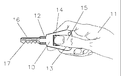
In FIG. 1 there is provided a biometric key 10 of the invention held
in the hand 11 having control portals 12. The key 10 has a key body 13 and
1.o a sensor 14 being contacted by thumb 15. The key 10 is also provided with
blade 16 having wards 17.
In FIG. 2 the key 10 is shown inserted into lock barrel 31 which is
fitted into mating aperture 19 of lock body 20 having lock tongue 21. The
barrel 31 has contact portals 22 and also has upper component 23 which fits
into mating recess 24. The barrel 31 is also provided with wires 25. The
lock body 20 is of mechanical nature having a custom wire bus (not shown).
The lock body 20 incorporates a slider bar 21A having slot 21 B for
engagement with trigger latch 48 shown in FIG. 4A.
In FIGS. 3A and 3C the key 10 is shown having components in the
form of the sensor 14, insulator insert 27 and circuit board 28 which fits
into
recess 29 of insulator insert 27. Insulator insert 27 is slidably attached to
key body 13 and bonded thereto. The circuit board 28 is shown on both
sides as is key body 13, which is formed from sensor 14, insulator insert 27
and circuit board 28 as illustrated. Sensor 14 fits within recess 30 of
CA 02346592 2001-05-08
11
insulator 27 and, more specifically, is retained by retaining flange 30A of
recess 30. The circuit board 28 has wire leads or contact traces 28A which
bond or solder to corresponding tabs 26 on sensor 14. Circuit board 28 also
has at the end adjacent wire leads 28A sloping side edges 28B, which
engage with corresponding edges 28C of recess 29.
The key body 13 as shown in FIG. 3A and 3C also includes body
plates or flanges 13A and 13B separated by a slot 13C of complementary
shape to insulator insert 27 which receives insulator insert 27 as shown in
FIG. 3A.
In FIG. 4 the key 10 is shown fitted into a lock cylinder 18 having
contact portals 32. The cylinder 18 has flange 33 and end 34 having a slot
35. The cylinder 18 also has tumblers 36.
Contact portals 32 touch mating contact portals 22, when cylinder
18 is inserted into lock barrel 31. The contact portals 22 transmit electronic
signals with an external processor as hereinafter described through lock
body 20. Alternatively, and more preferably, the contact portals 22
exchange electronic signals with an processing unit in lock body 20 which
has an electronic interface with an external processor, such as a host
computer, as described hereinafter. The electronic interface with the outside
processor may be of any suitable type, such as USB, parallel, serial or
IEEE1384 firewire signals. This does not preclude conforming to IEEE
802.15 Wireless Personal Area Network (WPAN) including Bluetooth,
HomeRF, HighRate RF and wide spectrum RF. The processing unit may
also provide return electrical signals that control a linear motor or solenoid
CA 02346592 2001-05-08
12
38 which releases a cylindrical locking pin 39 which fits within bore 40 of
cylinder 18. Motor 38 has a spring loaded piston 41, which engages with
aperture 42 of locking pin 39. Motor 38 also fits within mating socket 43 of
barrel 31. Locking pin 39 has projection 44, which engages with slot 35 of
cylinder 18. Motor 38 also has contacts 47, which engage with wires 25.
There is also provided trigger latch 48 of barrel 31, shown in the locked
position and which is located on rotatable gear 48A shown in FIG. 4A which
has a protective sheath 49. The trigger latch 48 engages with slot 50 in an
unlocked position providing for maintenance of barrel 31. When unlocking
of lock body 20 is initiated, piston 41 retracts within motor 38 thereby
allowing locking pin 39 to rotate. There is provided a small pin 48B which
interconnects locking pin 39 and gear wheel 48A as shown in FIG. 4A
wherein pin 48B engages in hole 48C of locking pin 39 and also engages in
a selected recess 48D of gear wheel 48A. Latch 48 moves downwardly from
the position shown in FIG. 4 to unlock tongue or latch plate 21 by
engagement with slot 21 B shown in FIG. 2. The upper component 23 of
barrel 31 has screw threaded attachment holes 51A which facilitate
attachment to lock body 20. It will also be appreciated that as referred to
above lock 20 may incorporate a suitable processing unit (not shown) which
includes suitable software and a database to match and validate biometric
data in the form of a biocode provided by an electrical signal from sensor 14.
The processing unit may also interface with a host computer, through which
biocodes may be enrolled as described hereinafter. Wires 25 may be
connected to the processing unit or to the host computer. The lock 20 body
CA 02346592 2001-05-08
13
controls access in two different ways i.e. requiring a valid return signal
from
the processing unit to unlock the locking pin 39 as well as mechanical
tumblers 36 adding further security.
FIG. 5 shows key 10 inserted into keyway or slot 31A of cylinder
18 and FIG. 6 is taken along line A-A of FIG. 5. In FIG. 6 there is shown
individual insulators or insulator sleeves 50A and 51, which contact pins 52
and 53. A closer detail is shown in FIG. 6A which shows insulators 50A and
51 engaging in a press fit within key body 13 and contact pins 52 and 53
engaging within a press fit within mating insulators 50A and 51. Contact
lo pins 52 and 53 each have a barbed point 52A, which drive into a solder
puddle on circuit board 28. Insulators 50A and 51 are aligned normally to
a longitudinal axis of key body 13.
FIG. 7 is taken along line B-B of FIG. 5. There is shown contact
pin 55, which is a sliding fit within insulator 54, and fuzz button 57. The
purpose of fuzz button 57 is to provide electrical continuity between contact
pins 55 and 56 under the influence of its own spring pressure. Insulators 57
are shown aligned normally to the longitudinal axis of the key body 13. A
closer detail of this arrangement is shown in FIG. 8. An exploded view is
also shown in FIG. 8A.
FIG. 9 is a section along line C-C of FIG. 4, a detailed view of the
contact detail shown in FIG. 10, shows insulator 63 which is bonded within
barrel 31, contact pin 62 adapted for press fit within insulator 63, fuzz
button
64 and additional contact pin 65 which has a sliding fit within insulator 63.
An exploded view is shown in FIG. 10A.
CA 02346592 2001-05-08
14
The processing unit may be operated in either a stand alone
environment (platform independent) i.e. as described above or aided with a
remote host computer connected by any suitable means including serial,
parallel, or USB connection or IEEE 802.15 WPAN RF technology. The
s processing unit may comprise a Digital Signal Process (DSP) unit or ASIC
processor. The processing unit captures and extracts a biocode of the
fingerprint scanned by the biometric key. The biocode is a fingerprint map
or digital signature that permits identity verification of a person. The
extraction and matching algorithm is based upon minutiae comparison. The
lo maximum size of a biocode in this particular context may be 254 bytes. The
processing unit can manage up to 2048 biocodes in its own database or a
remote host computer may manage the database if more biocodes are
needed. In order to take full advantage of the features available, such as
administrative reports and user queries, a remote computer may interface to
15 the processing unit.
The processing unit may be a self-contained board using only an
external power source, an interface to the biometric sensor, and a
connection to the host computer. The processing unit may also contain on-
board RAM, ROM, communications interface, fingerprint recognition software
2 o and database manager, all integrated into an optimised device. It is the
task
of the system integrator to fulfil the relevant specifications for the entire
system operation.
There is a variety of enrolment means to enter a biocode into the
processor database. The most common is the remote host computer via a
CA 02346592 2001-05-08
suitable connection. A Smartcard Reader may also be used in conjunction
with a 10-key pad to control the processing unit. There is a multitude of
ways to initiate administrator functions in a stand alone environment.
The processing unit may also enrol biocodes directly to the point
5 of origin via the key. Users are grouped into two categories: administrator
and regular users. The administrator registers, checks and deletes the
authorised people in the database.
In FIG. 11, there is shown an alternative embodiment of the
invention, wherein key 10 is fitted within a stationary receptor body 18A and
1o electrical continuity is provided by FIGS. 12 and 13, which represent
sections along lines A-A and D-D of FIG. 11 and which relevant contact
detail is shown in a similar manner as shown in FIGS. 6 and FIG. B. In FIG.
12 there is shown contact pins 52 and 53 which are bounded by insulators
50A and 51 as described previously. Contact pins 52 and 53 touch mating
15 contacts 56 of receptor body 18A, which touch fuzz button 57. Wiring 66 is
attached to fuzz button 57 by solder 67 as shown in FIG. 14. Key 10 is
inserted in slot 68 of receptor body 18A as shown in FIG. 16. Wiring 66 is
routed in wire access grooves 69, which are shown in FIGS. 13 and 17.
Receptor body 18A is also provided with a light emitting diode 70, shown in
FIG. 16, which is a visual signal for acceptance (i.e. green) or rejection of
the signal (i.e. red). Wiring 66 has soldered points 66A, 66B, 66C and 67D
as shown in FIG. 17.
Receptor body 18A may be mounted inside a drawer, box, housing
of any security system whereby receptor body 18A may be wired to the
CA 02346592 2001-05-08
16
processing unit (not shown) in the security system which requires access by
biometric key 10. Thus in this embodiment there is no requirement of a
mechanical or electromechanical lock body 20 as shown in the embodiment
of FIGS. 1-10.
The sensor 14 may be obtained commercially from Siemens and
is sold under the Registered Trade Mark FingerTip. It is sold as part of a
module; which also includes a processing unit connected to the FingerTip
sensor chip by a conductor and the module is marketed by Siemens under
the Trade Mark TopSec 10 - Module A1Ø The module reads out of the
1o FingerTip sensor the biometric data, evaluates it and compares it to a
database contained in the memory of the module. It is emphasised that it is
only the sensor component that is utilised in the present invention and which
is incorporated in key body 13 as described herein.
However, the processing unit from the module is an example of a
suitable processing unit utilised in the present invention.
The key 10 may also include a smart card chip 14A (not shown)
shown on the same side as sensor 14 or on the opposite or obverse side.
It will also be appreciated that the invention may include within its
scope the abovementioned receptor body in the form of lock cylinder 18 or
stationary body 18A. The invention may also include the barrel 31 per se.
The smart card chip 14A may comprise an integrated circuit with
ISO 7816 interface and/or a processor integrated circuit and/or a personal
identity token containing IC-S.
In FIG. 18 there is shown a block diagram representing the chain
CA 02346592 2001-05-08
17
of events upon use of the biometric key of the invention wherein the
following events take place, i.e.
(i) the key 10 or 10A is inserted into lock cylinder 18 or
stationary receptor body 18A;
(ii) the key contacts make connection with the receptor body
contacts;
(iii) power is provided to the sensor 14 in the key 10, via the
receptor body 18 or 18A and the processing unit, from an external source;
(iv) a biometric is read through the sensor 14, and that data
1.o is passed through the key contacts and sent to the processing unit;
(v) the processing unit extracts biometric data signature, and
compares to previously stored biometric data signature for match;
(vi) if a match exists, the external signal latches or unlatches
(i.e. open/closed); and
(vii) the key 10 is removed from the receptor body.
In FIG. 19 there is shown a schematic diagram how enrolment of
biometric data signature may be accomplished via a host computer whereby:
(a) the host computer software requests personal and/or
demographic information relative to the authorised user;
(b) the biometric data signature is captured from the sensor
through the key, via the receptor body interfaced to the host computer;
(c) personal and/or demographic information is stored with
biometric data signature and stored within database of the host computer;
(d) a search is performed against the database for previous
- ----------- -- -- -
CA 02346592 2001-05-08
18
enrolments (i.e. prevents multiple enrolments under assumed names);
(e) if not found, authorised user is enrolled into database;
(f) if found, enrolment is denied; and
(g) database located on the processing unit and host
computer database is updated to reflect new enrolment.
It will be appreciated from the foregoing that the biometric key of
the invention is versatile in operation, has relatively simple structure and
provides a high degree of security.
In a variation of the foregoing it will be appreciated that the key
lo body may have inbuilt processor chip or processing unit instead of the
processing unit being incorporated in the receptor body.