Language selection

Search

Patent 2346832 Summary

Third-party information liability

Some of the information on this Web page has been provided by external sources. The Government of Canada is not responsible for the accuracy, reliability or currency of the information supplied by external sources. Users wishing to rely upon this information should consult directly with the source of the information. Content provided by external sources is not subject to official languages, privacy and accessibility requirements.

Claims and Abstract availability

Any discrepancies in the text and image of the Claims and Abstract are due to differing posting times. Text of the Claims and Abstract are posted:

  • At the time the application is open to public inspection;
  • At the time of issue of the patent (grant).
(12) Patent: (11) CA 2346832
(54) English Title: AN ANTENNA ALIGNMENT METER
(54) French Title: DISPOSITIF DE MESURE D'ALIGNEMENT D'ANTENNE
Status: Expired and beyond the Period of Reversal
Bibliographic Data
(51) International Patent Classification (IPC):
  • H01Q 1/12 (2006.01)
(72) Inventors :
  • HOLLIDAY, DAVID (United Kingdom)
(73) Owners :
  • BRITISH SKY BROADCASTING LIMITED
(71) Applicants :
  • BRITISH SKY BROADCASTING LIMITED (United Kingdom)
(74) Agent: MOFFAT & CO.
(74) Associate agent:
(45) Issued: 2004-11-30
(86) PCT Filing Date: 1999-10-15
(87) Open to Public Inspection: 2000-04-27
Examination requested: 2001-04-10
Availability of licence: N/A
Dedicated to the Public: N/A
(25) Language of filing: English

Patent Cooperation Treaty (PCT): Yes
(86) PCT Filing Number: PCT/GB1999/003418
(87) International Publication Number: WO 2000024083
(85) National Entry: 2001-04-10

(30) Application Priority Data:
Application No. Country/Territory Date
9822678.0 (United Kingdom) 1998-10-16

Abstracts

English Abstract


An antenna alignment meter (1) comprises a receiver (2) for detecting a
signal with predetermined characteristics and outputting data pertaining to
the detection
of the signal, and a controller (6) responsive to the data from the receiver
for controlling
generation of an indicator that the signal has been detected. The meter can be
used for
aligning an antenna with a signal source. The meter is arranged to monitor
signals
received by the antenna and to provide an indication of correct alignment of
the antenna
with a desired signal source when a signal of a predetermined frequency,
polarization,
symbol rate and error correction ratio is received.


French Abstract

L'invention concerne un dispositif de mesure d'alignement d'antenne (1) comportant un récepteur (2) pour détecter un signal présentant des caractéristiques prédéterminées et produire des données relatives à la détection du signal, et un organe de commande (6) sensible aux données provenant du récepteur pour commander la production d'un indicateur indiquant que le signal a été détecté. Le dispositif de mesure peut être utilisé pour aligner une antenne sur une source de signaux. Le dispositif de mesure est conçu pour surveiller des signaux reçus par l'antenne et pour indiquer l'alignement correct de l'antenne sur une source de signaux voulue lors de la réception d'un signal présentant une fréquence, une polarisation, un débit de symboles et un taux de correction d'erreurs prédéterminés.

Claims

Note: Claims are shown in the official language in which they were submitted.

7
THE EMBODIMENTS OF THE INVENTION IN WHICH AN
EXCLUSIVE PROPERTY OR PRIVILEGE IS CLAIMED ARE
DEFINED AS FOLLOWS:
1. An antenna alignment meter comprising a signal detector circuit for
detecting a signal with predetermined characteristics and outputting data
pertaining to the detection of the signal; a connector for connecting the
signal
detector circuit to an antenna; and a controller responsive to the data from
the
detector circuit for controlling generation of an indicator that the signal
has been
detected, wherein the predetermined characteristics uniquely identify a
required
satellite and comprise at least some of frequency, polarisation, data rate and
forward error correction.
2. An antenna alignment meter as claimed in claim 1, wherein the signal
detector circuit comprises a receiver circuit.
3. An antenna alignment meter as claimed in claim 2, wherein the receiver
circuit is controlled by the controller to receive signals having
characteristics
determined by the controller.
4. An antenna alignment meter as claimed in any one of claims 1 to 3,
wherein the controller comprises a processor having an associated memory in
which is stored data representing the predetermined characteristics.
5. An antenna alignment meter as claimed in claim 4, further comprising a
communications port, connected to the processor, for receiving data
representing
the predetermined characteristics.
6. An antenna alignment meter as claimed in any one of claims 1 to 5,
further comprising a display controlled by the controller for displaying
information relating to a detected signal.

8
7. An antenna alignment meter as claimed in any one of claims 1 to 6,
wherein the meter is operable in plural different operating modes, the meter
further comprising a user manipulable input connected to the controller for
user
selection of the operating modes.
8. An antenna alignment meter as claimed in claim 7, wherein the operating
modes comprise a detection mode in which the detector is operable to detect a
predetermined signal being received by an antenna connected thereto, thereby
to facilitate alignment of the antenna with a signal source.
9. An antenna alienment meter as claimed in claim 7 or 8, wherein the
detector comprises signal processing circuitry operable to process a signal
being
received by an antenna connected thereto to determine a data error rate in the
received signal, and the operating modes comprise an antenna alignment mode
in which the controller is operable to output data for display representing
the
quality of the signal depending on the data error rate, thereby to facilitate
skewing of the antenna into alignment with a signal source.
10. An antenna alignment meter as claimed in claim 9, wherein the
processing circuitry is operable to determine data error rates for both
horizontally and vertically polarized signals and the controller is operable
to
output data representing the quality of both horizontally and vertically
polarized
signals.
11. An antenna alignment meter as claimed in any of claims 7 to 10, wherein
the detector comprises a signal amplifier including an automatic gain control
circuit, and the operating, nudes comprise a signal strength mode in which
data
relating to the gain set by the automatic gain control circuit is used by the
controller to generate a display representing the strength of a signal being
received by the antenna.

9
12. An antenna alignment meter as claimed in any one of claims 7 to 11,
further comprising a power supply controlled by the controller, and wherein
the
operating modes comprise a standby mode in which the power supply is
switched off following a predetermined period of non-use of the meter.
13. An antenna alignment meter as claimed in claim 12, wherein the period
of non-use is measured as time elapsed between manipulations of the user
manipulable input.
14. A method of aligning an antenna with a signal source, the method
comprising: connecting the antenna to an antenna alignment meter; adjusting
the
orientation of the antenna until the antenna alignment meter indicates
detection
of a signal with predetermined characteristics; and locking the antenna in
position, wherein the predetermined characteristics uniquely identify a
required
satellite and comprise at least some of frequency, polarisation, data rate and
forward error correction.
15. A method as claimed in claim 14, further comprising adjusting the
orientation of the antenna until the antenna alignment meter indicates
reception
of a signal of substantially maximum strength.
16. A method as claimed in claim 14 or 15, further comprising adjusting
the orientation of the antenna until the antenna alignment meter indicates
reception of a signal optimum quality.
17. A method as claimed in claim 16, wherein a signal of optimum quality is
deemed to be received when the antenna alignment meter indicates reception of
horizontally and vertically polarized signals with substantially equal bit
error
rates.

10
18. An apparatus for aligning an antenna with a signal source, the apparatus
being arranged to monitor signals received by the antenna and to provide an
indication of correct alignment of the antenna with a desired signal source
when
a signal of a predetermined frequency, polarisation, symbol rate and error
correction ratio that uniquely identities a required satellite is received.

Description

Note: Descriptions are shown in the official language in which they were submitted.


CA 02346832 2003-05-12
AN ANrfF:NNA ALIt:NMEN'C METER
'The invention relates to an antenna alignment meter.
Background of the Invention
There arc ru~w se~~eral satellites in relatively close proximity to each other
(when seen front the ground) transmitting television at the same or similar
'i ti-equencies to one another. Many satellite receiver systems comprise a
fixed antenna
which is aligned with a single satellite to receive television signals
therefrom. '><'he
close proximity of several satellites all transmitting at the same or similar
icequencies makes it difficult to align an antenna with the correct satellite
during
installation. Using only ~:r signal strength meter it is all too easy for an
installer
mistakenly to align the antenna with a nearby satellite transmitting at the:
same
icequency as the correct satellite. Identifying and correcting such an error
is relatively
straightforward; when decoded and viewed on a television screen it will be
immediately apparent that the wrong signal is being received. However, relying
on
viewing the picture is time consuming and therefore undesirable.
I:p Summary of~thc Invention
'Che present invention aims to facilitate installation of a satellite system
by
improving t:he confidence of the correct signal being received.
In a broad aspect, then, the present invention relates to an antenna alignment
meter comprising a sigmrl detect or circuit for detecting a signal with
predetermined characteristics and c.>utputting data pertaining to the
detection of the
signal; a connector for c~,>nnecting the signal detector circuit to an
antenna; and a
controller responsive to the data teom the detector circuit for controlling
generation
of an indicator that they signal has been detected, wherein the predetermined
characteristics uniquely idt;ntify a required satellite and comprise at least
some of
frequency, polarisation, data rate and forward error correction.
In another broad aspect, then, the present invention relates to a method of
aligning an. antenna with a signal source, the method comprising: connecting
the
antenna to an antenna ali~;nrnent meter; adjusting the orientation of the
antenna until
the antenna alignment meter indicates detection of a signal with
predeter~rrrined
characteristics; and locking the antenna in position, wherein the
predetermined
characteristics uniquely iiderriify a required satellite and comprise at least
some of
frequency, polarisation, ~aata rate and tc>rward error correction.

CA 02346832 2003-05-12
7
(n yet another broad aspect. then, the present invention relates to an
apparatus
for aligning an antenna with a signal source, the apparatus being arranged to
monitor
signals received by the antenna and to provide an indication of correct
alignment of
_'i the antenna with a desired signal source when a signal of a predetermined
frequency,
polarisation, symbol rate and error correction ratio that uniquely identifies
arequired
satellite is received.
The above and further features of the invention are set forth with
particularity
in the appended claims and together with advantages thereof will become
clearer
from consideration of the following detailed description of an exemplary
embodiment of the inventicnn given with reference to the accompanying
drawings.
Brief Descri t-p ion ofthe 1)raw~ns~s
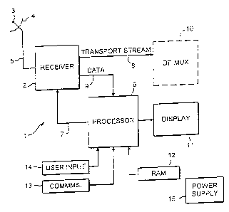
Figure 1 is a schematic diagram of an antenna alignment meter.
Detailed Description of an Eymbodiment of~,the Invention
Referring now to figure I of the accompanying drawings an antenna
alignment meter 1 comprises a receiver 2 which is preferably a digital
satellite
Network Interface Module ~NIM) by GI;C flesscy ~emiconduetors. The receiver 2
is connectable to the low noise block (l_,Nt_~) 3 of an antenna 4 via a
coaxial line 5.
A processor 6 is coon ectcd to the receiver 2 by way of a control path 7 and
is arranged to send control data to the receiver ~' via the control path 7.
The receiver
2 can be tuned to a signal ~;~f given characteristics depending on the control
data from
the processor O. When the receiver is receiving a signal having the given
characteristics the receiver outputs a transport stream on path 8 and a
"locked" flag
or signal on data path 9. 'I hu locked flag thus provides an indication to the
processor
2.5 6 that the receiver ? is receiving a signal of the given characteristics.
fhe transport stream contains all the service information carried in the
received signal. 'fhe inf~.>n~~ation may include several television signals
(video

CA 02346832 2001-04-10
WO 00124083 PCT/GB99/03418
3
and/or audio) and service signals. The transpor~ stream may therefore be input
to demultiplexer and decoder circuitry 10 to enable television pictures to be
viewed on a suitable monitor. However. it is envisaged that the meter 1 will
be supplied as a hand-held unit to facilitate installation of antennas on the
outside of buildings. As such the meter should be as small and light as
possible and therefore demultiplexer and decoder circuitry will not be
necessary because there will be no need to ~-iew television pictures.
Furthermore. such circuitry is expensive and ~~ould make the meter
prohibitively expensive for use in routine receiver system installations.
Normally, therefore, the meter 1 will not include the dernultiplexer and
decoder circuitry 10.
The processor 6 is also connected to drive a display 11. Among other
things, the processor 6 is arranged to cause the display 11 to display an
indication of when the receiver 2 is receiving a signal having the given
characteristics. The processor 5 has associated with it a memory including
RAM 12 in which is stored data defining among other things the given
characteristics of the signal to which the receiver 2 is to be tuned. A
communications port I3 is provided to enable the data in the RAM I2 to be
changed if required.
Operation of the meter I is controlled by a user input device 14,
typically in the form of keys connected to the processor 6. The processor 6
responds to manipulation of the keys by controlling operation of the receiver
2
and/or the display 1 I. The meter includes an internal power supply 1~ in the
form of replaceable or rechargeable batteries. The power supply is connected
to supply power to all of the units comprising the meter 1 and to supply power
to the LNB 3 via the receiver 2. The power supply is controlled by the
processor 6, which is arranged to activate the power supply and thus switch on
the meter in response to manipulation of the user input device 14.
In order to conserve power the processor 6 is arranged to monitor the

- CA 02346832 2001-04-10
WO 00/Z4083
. _ .,~iiyyiu~.:~~:
4
time bet«~een manipulations of the input device l4 and to cause the power
supply I S to switch off if the time exceeds a predetermined duration. say 3
minutes. Power is restored when the installer next manipulates the input keys
14. The processor 6 and the power supply 1 ~ may also cooperate to enable
battery status information to be displayed on the display I 1.
. Television signals broadcast by satellites have several parameters
which vary. Signals are transmitted on carriers at several different
frequencies
from a single satellite to enable the carriers to be distinguished from one
another. Signals are polarized, either vertically or horizontally. to increase
signal diversiy. Some signals carry information in analogue form and others
in digital form. Digital information is transmitted at different symbol rates
and
error correction ratios. During installation of an antenna it is only
necessary to
be able to identify yth confidence a single signal from the selected
satellite.
There are several combinations of the aforementioned signal
IS characteristics that can be used to identify uniquely a signal as
originating
from the required satellite. For example both Eutelsat and Astra 28.2 transmit
vertically polarized signals at 11.778 GHz carrying digital data at 27.5
Msymbols/s. but the data in the Eutelsat signal has a forward error correction
ratio (FEC) of 3/4 whereas the data in the Astra signal has an FEC of 2/3.
Thus a vertically polarized signal at 11.778 GHz carrying digital data at 27.5
Msymbols/s and an FEC of 2/3 uniquely identifies the Astra 28.2 satellite.
Therefore, by tuning the receiver 2 to receive a signal with these
characteristics, reception of the signal can be interpreted as indicating that
the
antenna is correctly aligned with the desired Astra 28.2 satellite.
~ A decision is made in advance regarding which characteristics can be
used to identify uniquely the required satellite. Data defining those
characteristics is stored in the RAM i 2 and used by the processor to tune the
receiver 2 to the appropriate signal.
During installation of an antenna an installer will first connect the

~
CA 02346832 2001-04-10
WO 00/24083 . PCT/GByy/O:i4i8
meter to the LNB .of the antenna by way of a suitable lead. The meter is then
switched on b3~ manipulating the input keys 14 and thus power is applied to
the LNB ~~ia the lead. A suitable prompt may be shown on the display 11, for
example "search for satellite". This will prompt the installer to search for
the
correct satellite by moving the antenna so that it is directed towards the
general area of the sky in which the satellite will be found. When the antenna
"sees" the correct satellite the meter will receive a signal with the unique
characteristics and therefore the receiver will respond by outputting a locked
flag on data path 9 to the processor. The processor 6 in turn responds to the
locked signal by changing the display to indicate that the desired satellite
has
been found. A message such as "Now on Astra 28.2" may be displayed for
example. An audible signal may also be output by suitable means (not
shown).
Further manipulation of the input keys causes the processor to toggle
I S through a series of options.
Firstly an indication of signal strength in the form of a graphical bar is
displayed. The GEC Plessey N1M includes signal amplifier with an automatic
gain control circuit that can be controlled to output data on data path 9
representing the gain setting. The gain setting is inversely proportional to
signal strength (the greater the gain the weaker the received signal). The
gain
data from the receiver 2 is therefore processed by the processor 6 to generate
appropriate data for display of the graphical .bar. A weak signal indicates
that
the antenna is not aligned properly with the satellite or that the line of
sight
between the antenna and the satellite is not entirely clear. Thus the
graphical
signal strength bar enables the installer to adjust the position of the
antenna to
correct alignment with the satellite.
Depending on the position of the antenna 2 on the surface of the earth
the LNB 3 may have to be skewed by a few degrees off ihe.axis of the antenna
so as to align properly with the polarized signals from the satellite. The GEC

CA 02346832 2001-04-10
WO OO/Z4083 PCT/GB99/03418
6
Plessey NIM includes signal processing circuitn~ which is able to output data
indicating bit error rates in the received data in terms of bit errors per
1000
received bits. The bit error rate is an indication of the quality of the
received
signals. Therefore in another mode of operation the processor 6 is arranged to
receive from the receiver 2, via data path 9. bit error rate data for both
horizontally and.vertically polarized signals. The processor 6 outputs this
data
to the display I 1 for display thereon. The installer is then able to adjust
the
skew of the LNB 3 to maximize the quality of the received signals by
equalizing the bit error rates of the horizontal and vertical signals.
Once it has been established that the antenna is pointing tov~-ards the
correct satellite the installer should lock the antenna in position so that it
remains fixed on the satellite.
Having thus described the present invention by reference to a preferred
embodiment it is to be well understood that the embodiment in question is
I S exemplary only and that modifications and variations such as will occur to
those
possessed of appropriate knowledge and skills may be made without departure
from the spirit and scope of the invention as set forth in the appended claims
and equivalents thereof.

Representative Drawing
A single figure which represents the drawing illustrating the invention.
Administrative Status

2024-08-01:As part of the Next Generation Patents (NGP) transition, the Canadian Patents Database (CPD) now contains a more detailed Event History, which replicates the Event Log of our new back-office solution.

Please note that "Inactive:" events refers to events no longer in use in our new back-office solution.

For a clearer understanding of the status of the application/patent presented on this page, the site Disclaimer , as well as the definitions for Patent , Event History , Maintenance Fee  and Payment History  should be consulted.

Event History

Description Date
Time Limit for Reversal Expired 2017-10-16
Letter Sent 2016-10-17
Inactive: IPC expired 2015-01-01
Grant by Issuance 2004-11-30
Inactive: Cover page published 2004-11-29
Inactive: Final fee received 2004-09-20
Pre-grant 2004-09-20
Notice of Allowance is Issued 2004-04-16
Letter Sent 2004-04-16
Notice of Allowance is Issued 2004-04-16
Inactive: Approved for allowance (AFA) 2004-03-23
Inactive: IPRP received 2003-10-24
Amendment Received - Voluntary Amendment 2003-05-12
Inactive: S.30(2) Rules - Examiner requisition 2003-02-11
Inactive: Correspondence - Formalities 2001-08-23
Letter Sent 2001-08-21
Inactive: Cover page published 2001-07-12
Inactive: Single transfer 2001-07-05
Inactive: First IPC assigned 2001-06-27
Inactive: Courtesy letter - Evidence 2001-06-19
Inactive: Acknowledgment of national entry - RFE 2001-06-18
Inactive: Correspondence - Formalities 2001-06-13
Application Received - PCT 2001-06-09
All Requirements for Examination Determined Compliant 2001-04-10
Request for Examination Requirements Determined Compliant 2001-04-10
Application Published (Open to Public Inspection) 2000-04-27

Abandonment History

There is no abandonment history.

Maintenance Fee

The last payment was received on 2004-09-15

Note : If the full payment has not been received on or before the date indicated, a further fee may be required which may be one of the following

  • the reinstatement fee;
  • the late payment fee; or
  • additional fee to reverse deemed expiry.

Please refer to the CIPO Patent Fees web page to see all current fee amounts.

Owners on Record

Note: Records showing the ownership history in alphabetical order.

Current Owners on Record
BRITISH SKY BROADCASTING LIMITED
Past Owners on Record
DAVID HOLLIDAY
Past Owners that do not appear in the "Owners on Record" listing will appear in other documentation within the application.
Documents

To view selected files, please enter reCAPTCHA code :


To view images, click a link in the Document Description column. To download the documents, select one or more checkboxes in the first column and then click the "Download Selected in PDF format (Zip Archive)" or the "Download Selected as Single PDF" button.

List of published and non-published patent-specific documents on the CPD .

If you have any difficulty accessing content, you can call the Client Service Centre at 1-866-997-1936 or send them an e-mail at CIPO Client Service Centre.


Document
Description 
Date
(yyyy-mm-dd) 
Number of pages   Size of Image (KB) 
Representative drawing 2001-07-12 1 7
Claims 2003-05-12 4 141
Description 2003-05-12 6 286
Description 2001-04-10 6 278
Claims 2001-04-10 3 126
Drawings 2001-04-10 1 14
Abstract 2001-04-10 1 17
Cover Page 2001-07-12 1 38
Abstract 2004-04-07 1 17
Cover Page 2004-10-27 1 38
Reminder of maintenance fee due 2001-06-18 1 112
Notice of National Entry 2001-06-18 1 203
Courtesy - Certificate of registration (related document(s)) 2001-08-21 1 136
Commissioner's Notice - Application Found Allowable 2004-04-16 1 161
Maintenance Fee Notice 2016-11-28 1 178
Correspondence 2001-06-18 1 23
PCT 2001-04-10 14 549
Correspondence 2001-06-13 4 187
Correspondence 2001-08-23 4 203
PCT 2001-11-19 1 41
Fees 2003-09-16 1 35
PCT 2001-04-11 8 340
Fees 2001-09-17 1 37
Fees 2002-09-19 1 38
Correspondence 2004-09-20 1 34
Fees 2004-09-15 1 35