Note: Descriptions are shown in the official language in which they were submitted.
CA 02347420 2003-06-20
VARIABLE FOCUS OPTICAL SYSTEM
Background of the Invention
This invention in general relates to a variable focus optical system
and in particular to a digital focusing imaging system that is particularly
useful in
such applications as symbology reading.
Field of the Inyention
Bar code techno~ogy has been used for almost thirty years in a variety
of industrial and retail. applications to rapidly provide machine readable
information
ZS about products and processes involving those pmduds. This technology has
enjoyed
its success becau~e"b~''coding removes human error from data acquisition and
entry
processes as well as being repeatable and fast.
By convention, bar codes are systematic markings that modulate
surface area in predetermined ways which encode information. Early bar codes
consisted of a series of bars and spaces printed or otherwise affixed to a
surface.
Here, information was encoded in linear fashion as an alternating series of
light and
30
CA 02347420 2001-03-09
WO 00/16147 PCT/US99/21178
-2-
dark line pairs of predetermined sizes and sequences which represented agreed
upon
alphabets that translated directly into human understandable form with
suitable
decoding means.
While bar codes may vary in their use of formal encoding/decoding
schemes, all characteristically share some common properties. For example, the
density or amount of information that can be represented over a given surface
area
depends on the ability to form and read some minimum sized mark by which
information may be transferred from code to reader. The size of such a mark is
obviously limited by the means by which it can be formed and the ability of
the
reader to "see" or resolve it; the smaller the mark the higher the density and
vice-
versa. In earlier "linear" or 1D bar codes (actually two-dimensional
structures),
information was encoded along only one dimension where density depended on the
width of the thinnest light-dark line pair. In emerging more elaborate 2D, or
matrix
codes, information is also encoded by the smallest segment used to modulate a
surface area, but now along two directions.
Linear bar codes are typically "read" with laser scanners that project
a narrow beam of light that is swept across the code being modulated thereby
in
accordance with the variations in the code's particular pattern. The modulated
light
reflected or transmitted (transmission code) by the code is detected, and the
information carried in the modulated return beam is extracted via suitable
decoding
software resident in a general purpose computer or dedicated microprocessor.
Laser
scanning type readers are known to exist in both hand held and stationary
forms.
Common hand held scanning devices include wands that directly
contact the code, lasers for distant scanning, and two-dimensional
photodetector
arrays such as charge coupled devices (CCD's) or complementary metal oxide
semiconductor (CMOS) arrays.
Wands operate by projecting a small beam of radiation onto the bar
code. The diameter of the beam is made small enough to be modulated by the
code
and sampled fast enough to generate an electrical signal from which the
required
information can be easily extracted. Wands are limited in application to
situations
CA 02347420 2001-03-09
WO 00/16147 PCT/US99/21178
-3
where direct contact is possible and are therefore not suitable for any
applications
requiring finite working distances.
Hand held laser scanners are suitable where large working distances
are important because the lasers used can be focused to appropriately sized
S interrogation spots at long distances. Typically, a laser diode is used to
project a
beam of radiation that is focused and scanned over a bar code area by
reflecting the
beam from an oscillating mirror or rotating polygon minor. The return beam is
collected by suitable optics and directed to a photodetector to generate an
electrical
signal far subsequent downstream processing.
Stationary laser systems are also in widespread use for a variety of
non-contact applications and are widely available at cash registers in
supermarkets
and the like so are now commonly known even to retail customers.
Two-dimensional array based systems operate by imaging a bar code
on to a CCD or CMOS array which then generates an analog signal, typically at
video rates, that represents the variation in intensity of the image. The
intensity
variation is typically converted into digital signal form and information is
extracted
via look-up tables (LiJT's) or the like.
All these bar code reading methods share the need to resolve details
at the level at which information is encoded (high vs. low density), the
ability to read
over the required working distance (near or distant codes), and the ability to
operate
under available lighting conditions or to provide artificial illumination to
give
adequate signal-to-noise ratios (detector sensitivity and lens speed).
Obviously, these
requirements are related and vary with the demands imposed by a particular
application and the economics of the available solutions. Problems associated
with
bar code readers appearing in the patent literature and reflect considerations
such as
resolving power, working distance, targeting or aiming and framing,
illumination
delivery.
For example, resolving power in laser scanning systems is related to
the size of the minimum waist of a laser beam, assuming a Gaussian energy
profile.
For maximum power, the waist needs to be smallest to read high density bar
codes.
CA 02347420 2003-06-20
Also, it is known to provide focusing optics with laser scanners to increase
working
distance or provide a series of working distance zones within which bar codes
can be
read. For example, US-A-4°920°255 discloses a stationary
scanning system
including a ranging means for determining bar code position and automatically
adjusting the exist separation between various elements of a lens assembly to
set an
appropriate focal length to control spot size.
Other patents, for example, US-A-5 641 958, US-A-5 347121. and
US-A 5 479 011, advocate~selectivefy adjusting the size of the aperture stop
of the
optics used in conjunction with the laser beam to selectively provide
different
working distances with different depths of field that vary with aperture stop
size.
US-A 5 173 603 describes a scanning laser system in which a
rotating polygon is used with a rotating spinner canrying a plurality of
spherical
mirror segments to focus the laser at different working distances.
Commercially available hand held fixed focus CCD based imaging
type bar code readers have been marketed, but are limited in use to fixed
working
distances.
While many approaches havelbeen used to solve bar code problems
related to resolving power, working distance and the provision of adequate
signal
levels, there still remains a need for a bar code reader that ogers the
convenience of
hand held operation and appreciable working distance for use in decoding not
only
linear bar codes but also matrix or 2D codes.
Summary of the Invention
Accordingly, the present invention seeks to provide a variable focus
ZS optical system that is particularly suitable for use in a hand held bar
code reader that
is capable of reading linear both high- and low-density and 2D bar codes over
an
appreciable working distance. Preferred forms of the system of the invention
may
also provide:
a variable focus optical system that utilizes a continuously rotating
focusing disk for providing a plurality of focusing zones from which
one may be selected as best while the disk continues to rotate;
CA 02347420 2001-03-09
WO 00/16147 PCT/US99/21178
-5
a focusing objective lens system for use in resolving 2D and linear
bar codes over a working distance that at least in part overlaps;
a hand held bar code reader for reading linear and ZD bar codes in
low ambient lighting conditions;
a hand held bar code reader that has omnidirectional reading
capabil ity;
an omnidirectional hand held bar code reader having an optical
system that may be tilted through an appreciable predetermined angle
with respect to normal incidence and still be able to resolve 2D and
linear bar codes; and
a hand held bar code reader having a through-the-lens (TTL)
targeting system by which the reader and its angular field of view
with respect to a bar code may be set to assure that the bar code is
within the viewable area and working distance of the reader.
Accordingly, this invention provides a variable focus optical system
comprising a housing and a two-dimensional photodetector having an active area
positioned within the housing. The variable focus optical system of the
present
invention is characterized by an objective taking lens positioned with respect
to the
two-dimensional photodetector to image on its active area, the objective
taking lens
including a plurality of stationary lens elements fixedly aligned along an
optical axis
and at least one focusing element continuously rotatable about an axis offset
with
respect to the optical axis, the focusing element being moveable transversely
with
respect to the optical axis to change the focus of the objective taking lens,
as the
focusing element continuously rotates, between at least two focusing zones so
that
the objective taking lens can image over working distances that at least
partially
overlap. In this variable focus optical system, the focusing element is
preferably a
rotating disc that carries optical shims or other light-controlling elements
to change
the optical path length or other characteristics through the objective to the
photodetector, which is preferably a CCD or CMOS device. Good results can be
realized using an objective taking lens having a nominal effective focal
length of
CA 02347420 2001-03-09
WO 00/16147 PCT/US99/21178
-6
14.00 mm with an F/# of 5.6. A through-the-lens (TTL) targeting system is
desirably
provided to visually assist the user to correctly position the system for a
variety of
objects to assure that the object will be captured within the imaging system
field of
view and otherwise be sharply imaged on the photodetector when the lens is
focused. Desirably, two different forms of artificial illumination are
provided; one to
accommodate nearby objects that may be either specular or partially diffuse
surfaces
and another for more distant objects where the reflection characteristics and
structure in the illumination have less impact on image contrast. Elements of
the
photodetector may be used to assess available light levels and activate the
artificial
illumination system when ambient light levels are low. Ranging through the
lens can
be achieved by using elements of the photodetector and assessing high
frequency
content in a portion of the images formed as the imaging system is cycled
through its
various focus zone configurations at a suitable speed, for example,
approximately
600 RPM. A signal is preferably provided to set the focus of the objective in
one of
many possible focusing zones in conjunction with information provided by a
disk
position encoder. Desirably, all of the system's components are housed in an
ergonomically designed shell that is shaped to reduce user repetitive stress
injuries
while providing access to a user interface and a protective cover for the
various
systems therein.
This invention also provides a method of focusing a subject for the
capture of an image thereof, this method comprising aiming an objective taking
lens
and a two-dimensional photodetector having an active area positioned behind
the
objective taking lens by a predetermined distance at the subject so that the
subject is
located within the field of view of the objective taking lens and the
photodetector.
The method is characterized by continuously rotating a focusing element such
that
the focusing element moves transversely with respect to the optical axis of
the
objective taking lens to continuously change the focus of the objective taking
lens
between at least two focusing zones so that the objective taking lens can
image the
subject over a range of distances; forming a series of images of the subject
via the
objective taking lens on to the photodetector as the focusing element rotates;
CA 02347420 2003-06-20
determining the range separating the objective taking lens and the subject;
determining a best focusing zone of the focusing element that most sharply
images
the subject in accordance with the range determined as the focusing element
rotates;
and capturing an image of the subject with the photodetedor when the best
focusing
S zone of the rotating focusing element is in alignment with the objective
taking lens.
Brief Description of the Drawings
Preferred embodiments of the invention will now be describal,
though by way of illustration only, with reference to the accompanying
drawings,
wherein:
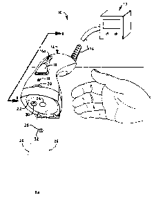
Fig. 1 is a schematic perspective view of one hand held imager
incorporating a variable focus optical system of the invention, this imager
being
shown imaging a nearby matrix, or ZD, type symbology and illustrating, among
other things, the reader's field of view, targeting features, and one form of
illumination it provides far lighting nearby symbologies;
Fig. 2 is a schematic perspective view of the imager shown in Fig. 1
imaging a relatively distant linear, or 1D, type symbology and illustrating,
again
among other things, the imager's field of view, targeting features, and
another form
of illumination provided for lighting relatively distant symbologies;
Fig. 3 is a schematic plan view_of a linear,, or 1D, type symbology
that the imager shown in Figs. 1 and 2 is capable of imaging;
Fig. 4 is a schematic plan view of a "stacked" type of symbology that
the imager shown in Figs. 1 and 2 is capable of imaging;
zS Fig. S is a schematic plan view of a matrix, or 2D, type of symbology
that the imager shown in Figs. 1 and 2 is also capable of imaging;
Fig. 6 is a schematic side elevation of the imager shown in Figs. 1
and 2 shown, in solid lines, norms! to a plane in which a symbology resides
and, in
broken lines, inclined at an angle of approximately 30° to that plane
to illustrate the
omnidirectional imaging capability of the imager;
Fig. 7 is an exploded schematic perspective view of the imager of
Figs. 1 and 2 illustrating its major subassemblies including a variable
focusing
imaging system of the present invention;
CA 02347420 2001-03-09
WO 00/16147 PCT/US99/2117$
Fig. 8 is a cross-section of the imager of Fig. 1 taken generally along
lines 8-8 therein;
Fig. 9 is an enlarged minor image of the cross-section of the
objective taking lens shown in Fig. 8 but with absent the window and focusing
disk
thereof removed;
Fig. 9a is a view, similar to that of Fig. 9, of an alternative objective
taking lens which can be substituted for that shown in Fig. 9;
Fig. 10 is an enlarged schematic perspective view of the focusing
disk of the objective taking lens system shown in Fig. 8;
Fig. 11 is an optical layout of the~imaging system of the imager for an
object (symbology) in the nearest focus zone of the imaging system (light
travels
through the system from left to right);
Fig. 12 is an optical layout, similar to that of Fig. 11, for an object
(symbology) in the farthest focus zone of the imaging system;
Fig. 13 is a diagram illustrating the various focus zones of the
imaging system of the invention shown along with the field of view and the
approximate working distances for imaging matrix and linear symbologies when
one
form of CCD photodetector is used in conjunction with the objective taking
lens of
Fig. 9;
Fig. 14 is a graph showing the variation in magnification and
horizontal and vertical fields of view of the invention with working distance
for one
form of rectangular CCD photodetector that may be used with the objective
taking
lens of Fig. 9;
Fig. 15 is a graph showing the variation in the polychromatic
modulation transfer curve with field position for the objective taking lens of
Fig. 9
for an object at best focus in the nearest focus zone, along with a curve
showing
dii~raction limited performance;
Fig. lb is a graph, similar to that of Fig. 15, showing the variation
with field position of the polychromatic modulation transfer curve for an
object at
best focus in the farthest focus zone;
CA 02347420 2001-03-09
WO 00/16147 PCT/US99/21178
-9
Fig. 17 is a graph showing the variation in saggital and tangential
field curvature and distortion with field position (position of the
photodetector, 0.0 is
on-axis and the vertical axis represents off axis location) for the objective
taking
lens of Fig. 9 when operating in the closest focus zone (near working
distance);
Fig. 18 is a graph, similar to that of Fig. 17 showing the variation in
saggital and tangential field curvature and distortion with field position
when
operating in the farthest focus zone {furthest working distance);
Fig. 19 is a graph showing the spectral response of a photodetector
(CCD) of the type which may be used in the imager of the invention;
Fig. 20 is a schematic perspective view of an alternative targeting
arrangement for use as part of the imager of Figs. 1 and 2;
Fig. 21 is a schematic perspective view of a rotating disk having a
continuous "quintic" or "quintic" and "shimmed" surface that may be used as
the
focusing element of the imager of Figs. 1 and 2;
Fig. 22 is a schematic perspective view of a rotating disk that carries
a generally continuous helical surface that may alternatively be used as the
focusing
element of the imager of Figs. 1 and 2;
Fig. 23 is a schematic section of the of rotating disk shown in Fig. 22
taken generally along line 23-23 thereof; and
Fig. 24 is a schematic section similar to that of Fig. 23 but with the
helical surface in a different rotational position.
Table I provides the complete lens prescription for the imaging
system of the imager shown in Figs. 1 and 2 in a standard output file format
from a
commercially available optical design program and may be used for purposes of
facilitating construction;
Table II is a listing of the various focus zones of the imaging system
showing the starting and ending zone positions for example focusing disk
thicknesses superimposed on the rotating focusing disk base thickness; and
CA 02347420 2003-06-20
Table III gives the relationship between symbology pel size and
corresponding reader working distance for one photodetector which may be used
in
the imager of the present invention.
Detailed Description of the Preferred Embodiments
As already indicated, the present invention relates, in a preferred
embodiment, to a focusable imaging system that it particularly suitable for
use in an
omnidirectional, focusing, hand held reader by which linear (1D) and matrix
type
symbologies or "bar codes" may be targeted, illuminated, andlor imaged via a
two-
dimensional photodetector array to provide an electrical signs( in analog
and/or
digital form for subsequent downstream signal processing by which information
encoded in the symbology may be extracted and converted to human readable
form.
The focusing imaging system of the invention is particularly suitable for use
in a
hand held reader that may be used in retail point-of sale environments and in
industrial applications where portability, variable lighting conditions,
flexibility in
use with different symbology modalities, and relatively large working
distances are
important considerations.
Figs. I and 2 show a hand held bar code imager or reader (genedally
designated 10) which, as described below, comprises an imaging system of the
present invention. Reader 10 comprises an ergonomic housing 12 whose shape is
designed to reduce user repetitive stress injuries while providing an easily
accessible
user interface that can be comfortably manipulated with one hand. This housing
IZ
is preferably as described and claimed in the aforementioned International
Application PCTIUS99/16502. .
As shown in Figs. 1 and 2, reader 10 is connected via a cable 14 to a
dedicated microprocessor or computer 17 that houses various system components
and software for anaiyaing electrical imaging signals provided by reader 10
and
performing other system housekeeping tasks as, for example, exchanging signals
related to ranging, power management, ambient light level, focusing, and
activation
of user interface signals. Components in housing 12 may also share one or more
of
such functions with microprocessor I7. If desired, reader 10 can be operated
without
being physically connected with associated apparatus, i.e., without need for
cable
CA 02347420 2001-03-09
WO 00/16147 PCT/US99/21178
_Ij_
14, for example by incorporating a radio frequency (IZF) module (not shown)
into
reader 10 for communication with a portable terminal (not shown). A suitable
module includes a radio frequency communication transceiver means to allow the
reader 10 to transmit and receive information, (including but not limited to
decoded
data, configuration commands and images) to or from another computer or
network.
The reader 10 can contain energy storage means (e.g., batteries) with which to
power it for a suitable duration independently of external sources. While
batteries
and RF will usually be connected, the utilization of IZF only, without
batteries, is
permissible as a means of reducing the need for cable connections. An
alternative to
an IRF communication module is an on-board infrared (IR) communication module
that operates via an IR link between reader 10 and an external transceiving
device
(not shown).
Protruding through the top of housing 12 is a two position switch
button 16 (or 16a) that is actuated manually by the user's thumb or index
finger,
depending on the manner of holding (gripping) reader 10. Also, provided are a
visual light signal 18 that operates to inform the user that the system has
been turned
on and is active and a visual light signal 20 that operates to indicate that a
bar code
has been successfully decoded. Signals 18 and 20 may be provided in a variety
of
suitable forms including strobe lights. Audible signals, or combinations of
visual
and audio signals, can also be employed.
As used herein, the term "hand held" means that reader 10 can be
held or gripped by the user for the addressing and reading of a variety of
symbologies. It will be appreciated, however, that reader 10 can be placed
into a
fixed or stationary position for the reading of symbologies within the field
of view
of the reader. For this purpose, an optical stationary table or other holding
apparatus,
represented by table 12a in Fig. 6, can be employed to advantage. A reader 10
holdable by table 12a or like holding means is nonetheless considered a hand
held
reader herein.
At the front of housing 12 is a clear window 22 having a clear
aperture section 24 (shown in broken lines) that serves as the entrance to the
reader's
CA 02347420 2001-03-09
WO 00/16147 PCTNS99/21178
-12-
imaging system. This imaging system has a rectangular field of view, the
horizontal
portion of which is shown in Figs. 1 and 2 as being bound by field rays 26,
which
subtend an angle of approximately 20°. The vertical field of view of
the imaging
system will typically be smaller because the imaging system photodetector will
normally be rectangular and positioned with its short dimension oriented
vertically,
as described below.
Fig. I shows a matrix or 2D type of bar code 28 positioned close to
reader 10 and illuminated with a diffuse type of lighting, as indicated by an
illumination pattern (generally designated 30), where available ambient light
levels
are too low to provide adequate signal levels.
Also seen in Fig. I is a targeting line 32 in the form of a line image of
a light source that is projected through various elements of the reader's
objective
taking lens as described below. Targeting line 32 is sized so that its extreme
ends are
within the reader's field of view In operation, targeting line 32 serves as a
means by
which the user positions reader 10 with respect to a 2D symbology, e.g.,
symbology
28, to ensure that the symbology is within the reader's field of view, i.e.,
the reader
can "see" it, and that the reader 10 is spaced from a symbology by a distance
which
will enable the reader 10 to sharply focus the symbology via the reader's
imaging
system so that the detailed pattern by which information is embedded in the
symbology can be resolved to extract meaningful information. As explained more
fully below, focusing and low light level detection also preferably take place
through
the lens by using at least part of the available photodetector pixels.
Fig. 2 shows that reader 10 also can be used to provide signals by
which a linear, or 1D, bar code (generally designated 34) can be decoded.
Because
bar code 34 is more distant than symbology 28 in Fig. l, a different type of
artificial
illumination may be employed where ambient light levels are inadequate. This
type
of artificial illumination, indicated generally by pattern 36, is more
directional (only
partially diffuse) than the diffuse pattern 30 but, even so, is sufficiently
far from the
bar code so that the structure of the illumination does nothing to render the
image
unreadable. Put another way, a bar code illuminated with this second kind of
CA 02347420 2001-03-09
WO 00/16147 PCT/US99/21178
-13
artificial illumination is in the far field of the artif cial sources and thus
does not
appear as structure of the code. Here again, targeting line light 32 is shown
just
extending over the extreme edges of bar code 34 for reasons set forth above.
In operation, a user depresses button 16 (or 16a), which turns on the
targeting light 32, and the reader's low light illumination detection system.
If low
light is detected, the reader artificial illumination systems are activated,
preferably in
a flicker mode to conserve power, especially where batteries are used to power
microprocessor 17 and other system components. Once the targeting line light
32 is
visible, it is used to position a symbology with respect to the reader's
imaging
system. Meanwhile, reader i0 operates to focus the objective lens of the
imaging
system on the symbology, and light 18 indicates that these operations are
underway.
Once a symbology is decoded, i.e., the image has been acquired and its
associated
signal processed and decoded, light 20 indicates that the reading operation
was
successful.
Fig. 3 shows a linear (1D) symbology 40 that is one of the types of
symboIogies that may be decoded by reader 10. The information in such a
symbology is contained in a series of modules which are formed by alternating
the
width of a series of parallel lines. As is conventional and typical of such
bar codes, a
linear bar code 40 consists of quiet zones 44 at each extreme of the code,
start and
stop modules at each end of the code, and the actual information carrying
modules
46 in the center. Information is only encoded in the horizontal dimension
(width),
with the vertical dimension (height) being used redundantly. Because of this,
these
codes have relatively large width (perhaps up to 100 mm or more) compared with
their height (typically 12-25 mm), and this basic structure results in a
relatively
inefficient storage of information per unit of occupied area.
The need to encode more information per unit area has driven the
development of two-dimensional symbologies. One method to increase efficiency
of
such codes is to reduce the amount of vertical redundancy (in effect making
shorter
bars) while keeping a large sized find pattern at both ends of the code.
Figure 4
CA 02347420 2001-03-09
WO 00/16147 PCTNS99/21178
_J4
shows a "stacked" code 52. Because of the loss of vertical redundancy,
artifices such
as row/column indicators may have to be introduced to ease user operation.
While 1D codes 40 and stacked codes 52 are designed for scanning
by lasers, when imaged they can be decoded by the present imager with suitable
algorithms.
Another type of 2D symbology is known as a matrix code. Fig. 5
shows a typical matrix code 54, which can also be decoded by reader 10. Matrix
technologies offer higher data density rates than stacked codes in most cases,
as well
as orientation independent scanning. A matrix code is made up of a pattern of
cells
where the cells are typically square, hexagonal, or circular in shape. Such
codes
typically have a location section 56, a clocking section 57, and an
information
section 58. Data is encoded via the relative positions of these light and dark
areas, in
relationship to the clock signal. Like the more advanced stacked codes, error
correction encoding schemes are used to improve reading reliability and enable
reading of partially damaged symbols.
The powerful combination of imaging, relaxed printing/marking
tolerances, absence/presence information encoding and error correction, allow
for
matrix symbols to be printed, etched, dot-peened, sprayed, or affixed.
Typically,
matrix codes have higher information density capacity, generating smaller
codes for
a given cell size (i.e., pels). Information is typically encoded via pel sizes
of 127,
190, 254 or 381 pm {5, 7.5, 10 or 15 mils). Because of these properties,
reader 10
needs to be much closer to such codes than to linear codes.
While size (and the desire for small pel sizes) drives matrix code
applications, 1D code requirements are driven by width. Nevertheless,
coexistence
of matrix and 1D bar codes is envisioned for a number of years. The imaging
subsystem of reader 10 is uniquely suitable for decoding both types of codes
over a
working distance that ranges from about 38 to 406 mrn (1.5 inches to 16
inches).
In addition, the image captured can also be utilized for further
processing. Printed text within an image, with or without 1D or 2D symbology
information, may be processed using optical character recognition (OCR)
algorithms
CA 02347420 2001-03-09
WO 00/16147 PCTNS99/21178
-IS
to render machine-readable information. In addition, again with or without
1D/2D
information, the image may be parsed and/or compressed for further processing
at a
remote site or later time.
The variety of applications for 2D codes can be glimpsed from
sampling, for example, the "A"s shown in a number of industry standards (e.g.,
EIA-706 Electronic Industry Association, Component Marking Standard; SEMI
T2-95 Specification for Marking of (Silicon) Wafers with a 2D Matrix Code;
AIAG
B-4 Automotive Industry Action Group Component Marking Standard; or the
proposed UPU S28-1 Universal Postal Union (none of which are shown).
As already mentioned, reader 10 can image codes omnidirectionally,
as illustrated in Fig. 6 which, in solid lines, shows reader 10 reading a code
normal
to a surface 60 to which a code has been applied. In broken lines, reader 10
is shown
reading the same code while inclined at 30° to the normal to surface
60. As also
shown in Fig. 6, reader 10 can be held stationary in, for example, a notched
holder
12a for the reading of code applied to a surface 60 which is movable to a
different
position shown in broken as surface 60'. Thus, relative movement between
reader 10
and code carrying surfaces (60, 60') can be accomplished by moving either or
both
of the reader and the surface.
Reader 10 may also be rotated about the normal at a 30° tilt and
still
read a code, thus being omnidirectional. This property is a consequence of the
ability
of the objective lens to adequately resolve detail even when in the
illustrated tilted
attitudes shown in Fig. 6
As seen in exploded fashion in Fig. 7, housing 12 of reader 10
comprises a top housing section 70 and a bottom housing section 72. Sandwiched
between top housing section 70 and bottom housing 72 is a CPU board 74 which
carries a power control board 76. Button 16 (16a) fits in top housing section
70 with
portions of it extending through to activate a two-position switch assembly 71
previously mentioned. Cable 14 is attached to housing 12 in a well-known
manner to
relieve any strains imposed during use.
CA 02347420 2001-03-09
WO 00/16147 PCT/US99/21178
-!6
In the forward section of housing 12 is located the previously
mentioned imaging system (generally designated 80), a dark f eld illuminator
82 that
operates in combination with a diffusing reflector 86 to provide the
previously
mentioned diffuse illumination pattern 30, and a bright field illuminator 84
that
operates to provide the partially diffuse illumination pattern 36 shown in
Fig. 2.
Also included in housing 12 is a bezel 88 and front cover 90 that
operate to provide various system access openings while assisting in excluding
unwanted radiation from entering imaging system 80.
As shown in Fig. 8, imaging system 80 includes an objective taking
lens 92 and a focusing disk 94 therefor, this disk 94 carrying various optical
bi-piano
parallel plates (i.e., optical shims) to provide a zone focusing lens to be
described in
more detail later. Disk 94 is rotationally driven at approximately 600 RPM by
a
motor 96 that is mounted about an axis of rotation 91 offset with respect to
the
optical axis, OA, of imaging system 80. Motor 96 is operated under the control
of
microprocessor/computer 17 and/or CPU board 74. The rotational speed of disk
94
can vary over a considerable range. Any speed sufficient to permit sampling
through
optical zones of disk 94 can be employed, although from a practical point of
view it
is desirable to rotate the disk at a speed that permits sampling within a
practical and
efficient time frame and to reduce blurring effects due to hand motion.
Operation of
disk 94 at high rotational speeds that reduce image contrast undesirably
should be
avoided. Good results can normally be obtained at speeds in the range of 300
to 600
RPM.
Dark field illuminator 82 carries a series of light emitting elements 98
on an otherwise transparent substrate to illuminate a diffusing reflector 86
which in
turn redirects the reflected illumination forwardly through clear window 22 to
provide pattern 30. The surface of diffusing reflector 86 has scattering
characteristics suitable for diffusing illumination incident thereto, and the
size and
location of emitting elements 98 are chosen so that they do not introduce
shadowing
at the plane of illumination.
CA 02347420 2001-03-09
WO 00/16147 PCT/US99/21178
_l7_
Bright field illuminator 84 comprises a plurality of light emitting
elements 100 that radiate directly through clear window 22 to provide pattern
36.
Both types of illumination are under overall system control with pattern 30
being
used primarily for nearby codes, particularly those with specular surfaces,
and
S pattern 36 for distant codes where any structure in elements 100 is obscured
on a
symbology because of the distance between window 22 and a distant code; this
aids
in reducing noise problems while increasing signal levels under what would
otherwise be low ambient light conditions. Apparatus and methods for the
illumination of machine readable syrnbologies are disclosed and claimed in the
aforementioned International Application PCT/US99l7C~C~ claiming priority
from U.S. Application Serial No. 09/151,765.
A CCD detector (generally designated 93) is positioned along optical
axis OA and is rectangular in shape with square active pixel areas that can,
for
example, be nominally 7.5 pm on a side and have VGA pixel density. While a CCD
is illustrated, CMOS detectors may also be used, as may other CCD's or CMOS's
having different pixel active areas and resolutions. However, the choice of
pixel size
does influence sensitivity to light and has an impact on lens focal length and
aperture, or light gathering ability requirements.
As shown in Fig. 9, the objective taking lens 92 comprises an
open-ended conical lens barrel 102 in which are arranged, in left to right
sequence
along optical axis OA, a first positive lens 104, followed by a nested lens
group
comprising a negative lens 106, a following positive lens 108, and a final
positive
lens 110. Lenses 104 and 106 are of polycarbonate while lenses 108 and 110 are
of
acrylic resin.
A spacing element 112 is provided to set the axial separation between
lens 104 and the following three-element group and has an internally serrated
or
stepped surface 115 for stray light control. Lens elements 106, 108, and 110
are
provided with complementary configured structures that facilitate the nesting
of lens
element 106 and 110 on either side of lens element 108. Lens element 108, in
turn,
includes an annular region that seats in lens barrel 102 to center the three-
element
CA 02347420 2001-03-09
WO 00/16147 PCTNS99/21178
_l8_
group along the optical axis. Lens element 104 likewise is seated in the
forward end
of lens barrel 102 and on the forward end of spacer 112 to locate it axially
and
otherwise center it. All of the lens elements are retained in lens barrel 102
via a front
cover 113 that snap fits to lens barrel 102.
Lenses 104-110, lens barrel 102, spacer 112, and front cover 113 are
all preferably made of plastic so that they can be easily mass produced using
injection molding techniques. In addition, the nesting properties of these
elements
make them amenable to automated assembly. However, the elements of objective
taking lens 92 may be provided in suitable optical glasses or other suitable
optical
plastics as, for example, polystyrene.
Fig. 10 shows focusing disk 94 and its corresponding axis of rotation
91 that is offset with respect to optical axis OA. Disk 94 comprises a series
of more
or less raised shims 130 each of which has a thickness suitable to focus light
from
the objective lens 92 on CCD 93 when a bar code is positioned in a specific
one of a
number of corresponding zones forward of reader 10. Because the shims used in
disk 94 differ in thickness for this purpose, the individual masses of the
shims 130
are correspondingly different, and thus the shims are arranged in staggered
fashion
near the circumferential edge of disk 94 to rotationally balance it as it
spins at, for
example, 600 RPM. This obviously reduces the level of vibration for reader 10
while
being held by hand and also assures adequate motion stopping ability during
the
interval during which an image is captured on CCD 93. Shims 130 are preferably
molded of light transmitting polycarbonate, or other suitable optical plastic,
to
required thickness and fixed in place via ultrasonic welding. If desired, disk
94 can
be molded or machined as a unitary structure having surface topography or
structure
adjacent the circumferential edge of disk 94 and predetermined to provide
desired
optical properties. A disk 94 formed by extrusion molding material, such as
poly(methyl methacrylate) or polycarbonate, can be employed. Shims, or other
optical control surfaces to be described, operate to maintain the apparent
location of
CCD 93 constant as seen through objective lens 92 from different bar code
positions
and hence maintain the required image quality for bar codes in different
positions.
CA 02347420 2001-03-09
WO 00/16147 PCT/US99/21178
-19
For this purpose, twelve bosses have been provided for one specific lens
described
below.
Disk 94 is provided with a position encoding strip 134 (only partially
shown) that is decoded in a well-known manner via a photodetector and
associated
electronics 133 to permit the position of a particular shimmed boss with
respect to
the optical axis OA to be determined and set as required. Here, the position
encoding
strip 134 includes a reference symbol 131 which informs the encoder that the
disk
94 is in alignment with the reference location. From the reference location,
decoder
133 counts pulses generated by passing light and dark lines provided on
encoding
strip 134. The light and dark lines are of sufficient density to provide
precise
position information regarding the angular location of the disk 94 as it
rotates since
the number of pulses can be summed up with respect to the reference position.
Figs.
10 and 21 show reference symbol 131 and encoding strip 134 on the periphery of
disk 94. If desired, reference symbol 131 and encoding strip 134 can be
positioned
on disk 94 inwardly of shims 130 in a circle concentric with the periphery of
the
disk. Decoder 133 can be positioned correspondingly for decoding of encoding
strip
134.
The focus zone appropriate for a particular symbology position is
determined by a through-the-lens ranging system that utilizes a part of the
active
area of the CCD 93. As the disk is rotating, the image formed on a line of CCD
pixels is used to generate an electrical signal whose high frequency content
is
filtered and analyzed. The shim that produces the highest high frequency image
used
to image the entire bar code and information regarding its position on the
disk is
determined from decoder 133 which then dictates the exposure interval during
which
an image is captured. Image capture takes place over a 4 ms interval via well-
known
video capture techniques, and the resultant signal is sent via conventional
protocols
to CPU 76 and/or microprocessor/computer 17 for decoding analysis.
A hand held reader incorporating the variable focus optical system of
this invention, and a method of forming images, are disclosed and claimed in
the
CA 02347420 2001-03-09
WO 00/16147 pCT/US99/21178
-20
aforementioned copending International Application PCT/US99/XXX3~ (Agent's
reference 8357PCT).
Fig. 9 also shows a pick-off mirror element 121 positioned in the
space between first element 104 and second element 106, nearer second element
106, and just outside the marginal ray bundle defining the system field of
view so as
not to reduce signal strength by blocking light traveling along the path to
the CCD.
Pick-off minor element 121 includes a rotationally symmetric rear surface 123
and a
mirror surface 125. The mirror surface may operate by total internal
reflection or be
provided with a reflecting coating. Aspheric surface 123 and minor surface 125
operate in conjunction with an LED 117 and a bi-cylindrical lens 119 to
project
targeting light line 28 substantially along the optical axis OA with a small
amount of
parallax in the horizontal plane, but none in the vertical plane. LED 117,
which has a
typical asymmetric energy output, is focused in one azimuth to a sharp line
about
120 mm forward of mirror surface 125 via bi-cylindrical lens 119 and aspheric
surface 123, and in the other azimuth, it is focused by bi-cylindrical lens
119 onto
the mirror surface 125. From mirror surface 125, the image formed thereon
diverges
into object space to provide targeting line 28. At nearby distances of
approximately
38 mm (1.5 inches), the horizontal parallax of targeting line 28 is at its
maximum,
but even so is less than 6 mm from optical axis OA. LED 117 is preferably red
in
color for visibility and has an output power in the range of 3 to 5 mW
Fig. 9a shows an alternative means by which the targeting line 28
may be generated; a partially reflective, partially transmissive beamsplitter
114 is
positioned in the space between first element 104 and second element 106.
Beamsplitter 114 is used with a light module 116 to project targeting light
line 28
along the optical axis OA without parallax. A source 118, such as an LED, is
reshaped via a lenticular screen 120 or other suitable beam shaping, e.g.,
anamorphic, optics. The line image is projected onto the forward facing
surface of
beamsplitter 114 which reflects, for example, 10 percent of its intensity
toward
object space. Ninety percent of light from a bar code image is under these
conditions
transmitted through beamsplitter 114 to travel to CCD 93. Obviously, these
CA 02347420 2001-03-09
WO 00/16147 PCT/US99/21178
-21
percentages may be changed as requirements vary, the tradeoffs being the
visibility
of the targeting line 32 and the need for adequate signal levels.
The optical layout of the imaging system 80 is shown in Figs. 11 and
12 with two different shims in place. Fig. I1 shows a shim 132 that represents
the
system configuration for extreme nearby focus. Here, the thickness of the shim
132
is simply the base thickness of the polycarbonate disk 94 itself. Fig. 12
shows the
system configuration for the farthest focus zone with shim 132 comprising base
thickness section 133 and add-to thickness section 135; in reality, shim 132
comprises a continuous piece of plastic of the overall thickness needed for
that zone.
From the prescription data below, it will become apparent that the thicknesses
of all
the shims include the base thickness and a corresponding add-to thickness.
As seen in Figs. 11 and 12, the imaging system further comprises a
physical aperture stop 122 (see also Fig. 9), a cold window 140 to reject
unwanted
infra-red (IR) radiation, and a transparent protective cover window 140 for
CCD 93.
I S As previously mentioned, aperture 24 in Fig. 1 is simply a defined section
of clear
window 22.
The complete lens prescription for the layouts of Figs. 11 and 12 is
given in Table I in the form of a standard output file from a commercially
available
optical design program. The design was optimized at the nearest (42 mm) and
farthest (360 mm) optimal working distances, referred to as Configuration 1
and
Configuration 2 in the prescription.
Additional considerations in implementing the present imaging
system are set for forth below using the following definitions.
Working Distance. This distance from the exterior surface of the
window to a bar code. This is consistent with the conventional usage of the
term if
one considers the window to be the first element in the optical assembly.
F-number, F-stop, or F/#. This term refers to the image space F/#,
which is the ratio of the effective focal length (EFL) of the lens to the
paraxial
diameter of the entrance pupil. This parameter characterizes the light-
gathering
ability of the lens for objects at infinite conjugates.
CA 02347420 2001-03-09
WO 00/16147 PCT/US99/21178
-22
Working F/# . The working F/# is defined by:
W = 1/(2sinB)
in which 8 is the angle that marginal rays make with the optical axis at the
image
plane. The marginal ray is traced at the specified conjugate.
Piael. A CCD sensor element
Pel. A two-dimensional bar code picture element
As explained earlier, the imaging optics were designed to form
images (e.g., one and two-dimensional symbols) on a CCD sensor over a range of
device-to-object distances, within the lens parameters and constraints
presented
below. Further considerations in the design having to do with specific system
applications were as follows.
As described earlier, the one-dimensional bar codes consist of a series
of alternating black and white lines of varying thickness, where data is
encoded by
the relative positions of the transitions from black-to-white or white-to-
black while
the two-dimensional bar codes comprise a number of different symbologies, but
each is essentially a grid of square pets that are either nominally black or
nominally
white.
The closest acceptable working distance is considered to be 38 mm
(1.5 in). Furthermore, no target is to be placed at a working distance greater
than 400
mm (15.75 in.) in order to fill the format in any orientation.
The lens is of fixed focal length. Various magnifications are be
achieved by varying the working distances within the range given above.
The smallest two-dimensional bar code pel dimension to be imaged is
about 0.13 mm (5 mil), and this covers at least 3 CCD pixels when aligned with
the
orientation of the CCD pixels. The longest one-dimensional bar code target to
be
read is about 100 mm (4 in). The target resolution required to find the edges
in this
target is typically set to 0.25 mm (10 mils).
No dynamic longitudinal translation of any component including the
CCD is permitted. Focusing over the full range of working distances is
achieved by
inserting piano-parallel plates of different thickness into the back focus of
the lens
CA 02347420 2001-03-09
WO 00/16147 PCT/US99/21178
-23-
92. These plates are mounted on the rotating disk 94 such that the optical
axis passes
through the wheel at a radius of 21.54 mm (0.848 in). This method of focusing
divides the range of working distances into a number of discrete "focus
zones". The
image is best focused at the center of each zone and becomes increasingly less
so
towards the ends. The end of a zone is determined by the "minimum modulation"
part of the performance specification.
The lens is optimized over the full field (diagonal) of the CCD, with
uniform weighting of all field points. This does not imply that the
performance is the
same over the entire field. The rationale behind optimizing over the full
field is that
the largest bar codes may cover much of the field in one dimension and may be
off_center in the other. Also, this approach allows for some misalignment of
the
CCD with the optical axis during assembly.
At any point within the full range of working distances, the minimum
design modulation for an on-axis field point is about 20% at 66 line pairs/mm
in
image space.
No vignetting is permitted the entire field of the CCD, because some
decoding algorithms are sensitive to changes in illumination across the image.
The lens 94 is achromatized over that part of spectral range of the
sensor coincident with the visible part of the spectrum. A filter was provided
to
attenuate transmitted light in the near infrared part of the spectrum. In
designing lens
94, it was assumed that the target may be illuminated by room lighting,
sunlight, or
by a bank of red LED's on the device in the event that the background
illumination
was insufficient.
The maximum permissible linear distortion from the center to the
edge of the full field of the CCD, and over the full range of working
distances, is
~2% as is shown Figs. 17 and 18.
Far design purposes, it was assumed that CCD 93 was to be, for
example, a Panasonic MN3776AE device of size (H x V) 4.788 x 3.589 mm,
comprising 640 x 480 square pixels having a 7.SIt pitch. The spectral response
for
this device is shown in Fig. 19.
CA 02347420 2001-03-09
WO 00/16147 PCT/US99/211'18
-24
All lenses were made from plastic materials suitable for injection
molding.
There were also a number of mechanical constraints taken into
consideration; namely that:
(a) The distance from the inner surface of the front window to the
image plane (CCD) was to be 51.806 mm.
(b) The distance from the inner surface of the front window to the
vertex of the first element was to be 16.3 mm.
(c) The distance from the surface of the rotating disk nearest the
target to the image plane (CCD) was to be 16.78 mm.
All optical surfaces are coated with a single-layer quarter-wave
antireflection coating centered at 580 nm. This wavelength is a compromise
between
the peak sensitivity of the CCD (520 nm) and the illumination from the on-
board
bank of red LED's (660 nm).
The adopted focus zones are delimited by the points at which the
on-axis MTF falls to 20%. Using 12 zones allows an exposure time of 4 ms when
the disc is rotating at 600 RPM. The zones are as shown, for example, in Table
II
and graphically in Fig. 13 for the horizontal field of view. Fig. 13 also
shows the
working distances corresponding to matrix bar codes with 127 pm (5 mil) and
178
pm (7 mil) gels.
Fig. 14 shows the relationship between system magnification,
horizontal (width) and vertical (height) field of view (FOV) and working
distance in
millimeters. Here, the magnification of the lens varies as a function of the
working
distance, and the image is always inverted. A first-order magnification
calculation
may be performed using the Newtonian form of the lens equation. For a system
in
air, the absolute ratio of image to object height, m, is given by the
relationship
m =flx
in which, f is the focal length of the lens, in this case 14 mm, and x is the
distance
from the object to the first focal point of the lens. In lens 94, the first
focal point lies
CA 02347420 2001-03-09
WO 00/16147 PCT/US99/21178
-25
22.8 mm behind the front surface of window 22. The magnification equation
therefore may be rewritten using the working distance x' (in mm) as follows:
m = I4/(22.8 + x
This function has been plotted over the full range of focus zones in Figure
14. The
total field of view corresponding to the height and width of the CCD are also
plotted
in this Figure.
More focus zones may be added by reducing the rotation speed of the
disc or by decreasing the maximum exposure time. The performance at the ends
of
zones may be enhanced by adding more zones or by stopping the lens down. The
zones in Table II have been distributed using the same end-zone criterion over
the
whole range of working distances. It is possible that experimental data in a
particular
case may indicate that some zones require better performance than others. In
such
cases, the zones may be redistributed in a non-uniform manner.
It is possible to achieve focus for objects closer than the 40.2 mm
nearest working distance shown in Table II by adding zones with effectively
negative plate thickness. This may be achieved by making the base thickness of
the
rotating disc less than 1.524 mm in those zones, but this may make the disc
more
difficult to mold successfully.
The distortion of the lens varies as a function of its working distance.
Figs. 17 and 18 show distortion curves at the closest and furthest working
distances,
respectively. These graphs show the distortion from the center to the corners
of the
CCD along with field curvature.
To cover three CCD pixels with a 5 mil (0.127 mm) pel, a minimum
magnification of 0.177X is required. Solving for x" in the magnification
equation
given above yields a furthest working distance for a 5 mil target of 56 mm.
The
range of working distances for this and larger targets are shown in Table III
immediately below. These numbers assume that three pixels need to be covered
by a
target pel whose image is optimally aligned with the CCD pixels. If fewer
pixels can
be used to satisfy the Nyquist condition, the working distances will be
longer.
CA 02347420 2001-03-09
WO 00/16147 PCT/US99/21178
-26
TABLE III Pel Size And Workine Distance
Pel Size (mil Furthest working Furthest working
(mm)) distance distance
for normal viewing for 30 viewing angle
angle mm
mm
(0.127) 56.2 45.6
7.5 (0.190) 95.4 79.6
(0.254) 13 5.2 114.1
The variation with field position of the polychromatic MTF curves at
the nearest and the farthest working distances are shown in Figures I S and
16,
respectively. In each case the MTF shown is for the position of best focus
within the
5 zone along with diffraction limited performance.
Surface 1 S of Table I in the lens prescription is a 1 mm-thick Schott
BK7 substrate for a near infrared reflective coating. This is a multilayer
dielectric
stack having a transmission cut-on wavelength of 700 nm. Wavelengths longer
than
this will be reflected back out of the lens, while shorter wavelengths pass
through to
10 the detector 93. The purpose of this filter is to shield the CCD 93 from
the large
amount of near infrared light which the system might conceivable see, and to
which
the CCD 93 is still reasonably sensitive. The lens, however, is not corrected
for these
wavelengths.
The operating parameters given are for room temperature. However,
since the lens elements and lens barrel are all made from plastic, their
thermal
coefficients of linear expansion will be similar and all parts will change
dimension at
approximately the same rate.
The lens has been optimized for a stop radius of 1.40 mm, at which
setting the image space f/# is f/4.7. However, in order to achieve the
performance
specification at the ends of the focal zones, the stop radius was set to be
1.20 mm,
corresponding to f/5.5. Should there be insufficient light at this stop
setting, the lens
can be used at its full design stop, but the performance at the ends of the
zones will
deteriorate. Hence, it may be necessary to introduce more focal zones. If more
light
CA 02347420 2001-03-09
WO 00/16147 PCT/tlS99/21178
-27
than is required for this design is typically available, stopping the lens
down even
further will greatly improve its performance within any given focal zone.
The clear aperture over the first surface (the surface of the first lens,
not the window) of the clear aperture is currently 12 mm. Since this surface
is far
from the stop, the footprint of the rays through this surface roughly mimics
the shape
of the field stop, which in this case is simply the CCD 93. Thus, it is
possible to
shape the clear aperture over the first surface substantially rectangular with
rounded
corners without affecting the performance of the lens at all. Because of the
manner
in which the near field illuminator currently operates, the clear aperture of
the first
element can be made as small as possible at the expense of vignetting the rays
in the
corner of the field.
Fig. 20 shows an alternative to the previously described TTL
targeting system; this alternative system 160 comprises a lens barrel 162,
similar in
some respects to the previously described lens barrel but having a pair of
targeting
lasers which reside in housings 164 and 166 arranged on either side of lens
barrel
162. The housings 164 and 166 are pivotally mounted to lens barrel 162 via
living
hinges 168 and 170, respectively. Each housing includes a source and
associated
optical means for projecting a line image 190 or 192 of its respective source.
Adjusters 178, 180, 182, and 184 change the pitch and yaw of housings 164 and
166
with respect to lens barrel 162 to permit the projected images to be aligned
with
respect to one another at a cross-over point 200 along the optical axis, OA of
lens
176. This targeting is suitable far use where parallax issues are minimal.
Fig. 21 shows an alternative form of rotating disk for focusing
objective taking lens 92. A disk assembly 210 comprises a rotating disk 212
that
operates with a fixed element 214 to continuously vary the optical properties
of the
imaging system to achieve focus as disk 212 rotates. Disk 212 is provided with
a
"quintic" surface 216 (i.e., a surface in the form of an analytic function
represented
mathematically as a polynomial in x and y containing 5th order terms) that
operates
with another "quintic" surface to simulate the optical action of a continuum
of
equivalent spherical lenses of different dioptric power which add to or
subtract from
CA 02347420 2003-06-20
WO OO/i6147 pGT/US99/21178
-zs-
the basic power of the objective taking lens 92, as needed. As described more
fully
in US-A-4 650 292, the optical action of analytic function surfaces need not
reside in
a single rotating disk and a single fixed element, but rather, may be present,
for
example, in two or more rotating disks, either by themselves, or in
combination with
S fixed elements. Disk 2l2 may be provided with an encoding strip as
previously
described for establishing its angular rotational position. Also, as shown,
disk 21Z
rotates about an axis that is displaced from and parallel to the optical axis,
OA.
Fig. 22 shows yet another form of rotational disk that may be used to
practice the invention. A rotating disk 220 is provided with a helical surface
that
operates with a fixed wedge element 224 to provide a continuum of varying
thickness "optical shims". The helical angle is established by the required
thickness,
taking into account the effect of fixed wedge 224, and the nominal
circumferential
length of disk 220. As shown in Figs. 23 and 24, the combination of the disk
220 (at
different angular positions) with fixed wedge 224 provides the equivalent of
optical
shims of different thickness; the equivalent thickness in Fig. 23 being less
than that
of Fig. 24. Also, notice that the air space between disk 220 and faced wedge
element
224 remains constant with rotational angle of disk 220. This is brought about
by
fabricating disk 220 with a plano surface that faces the hypotenuse of fixed
wedge
element 224 while having the axis of rotation axis, RA, of disk 220 offset and
arranged at an angle with respect to optical axis On. Again, the angular
position of
disk 220 may be determined with a positional encoder scheme.
The optical action again need not reside in a single rotating disk and
a single fixed wedge, but rather, may be present, for example, in at least two
rotating
disks each provided with a helical surface that rotate relative to one another
such
ZS that their combined optical thickness continuously varies with relative
rotation of
the opposed helical surfaces to change, the optical path length of objective
taking
lens 92 so that a subject positioned at different locations within the field
of view of
the variable focus optical system 80 will be acceptably imaged on the active
area of
two dimensional photo detector 93.
CA 02347420 2003-06-20
-29-
~tL~'~ I Preacrintion~a~
Title: HHS. EFL=l4mm f15.6 5
GENERAL LENS DATA:
Surfaces . ZO
S Stop . I1
System ApertureFloat By Stop Size
:
Ray aiming On
.
X Pupil shift 0
:
Y Pupil shift 0
:
Z Pupil shift 0
:
Apodization Uniform, factor =
. 0.000000
Elf.. Focal 14.0016 (in air)
Len.:
Elf.. Focal 14.0016 (in image
Len.: space)
Total Track 53.339
.
Image Space 5.44947
F/#:
Pare. Wrkng 6.70976
F!#:
Working F/# 6.70544
:
Obj. Space 0.0160957
N.A.:
Stop Radius 1.2
:
Parax. Ima. 3
Hgt.:
per, Wig, : -0.216025
Entr. Pup. 2.56934
Dia.:
Entr. Pup. 37.804
Pos.:
Exit Pupil 2.4
Dia.:
Exit 'Pupil -16.0496
Pos.:
Field Type Image height in Millimeters
:
Maximum Field:3
Primary Wave: 0.546000
Lens Units Millimeters
:
Angular Mag. 1.07056
:
Fields . 3
Field ~rpe Image height in Millimeters
.
# X-Value Y-Value
Weight
1 0.000000
0.000000 1.000000
2 0.000000
2.100000 1.000000
3 0.000000
3.000000 1.000000
Vignetting Factors
# VDX VDY VCX VCY
1 0.0000000.000000 0.000000 0.000000
2 0.0000000.000000 0.000000 0.000000
3 0.0000000.000000 0.000000 0.000000
Wavelengths: 3
Units: s
Micron
# Value Weight
1 0.5460001.000000
2 0.4861301.000000
3 0.6562701.000000
CA 02347420 2001-03-09
WO 00/16147 PCT/US99/21178
-30
SURFACE DATA SUMMARY:
SurfaceType Radius Thickness Glass DiameterConic
OBJ STANDARD Infinity42 27.774560
1 STANDARD Infinity1.524 POLYCARB 18.7 0
2 STANDARD Infinity16.3 18.32 0
3 STANDARD -79.8 2.2 POLYCARB 11.84 0
4 EVENASPI~i-14.42 8.28 11.6 0
STANDARD -8.98 2 POLYCARB 4.24 0
6 STANDARD 3.67 0.355 3.5 0
7 STANDARD 6.8 2.2 ACRYLIC 3.52 0
8 STANDARD -10.06 0.85 3.44 0
9 STANDARD -117 1.8 ACRYLIC 3.2 0
STANDARD -4.5 0.6 2.94 0
STO STANDARD Infinity0.45 2.4 0
12 STANDARD Infinity1.524 POLYCARB 4 0
13 STANDARD Infinity0 POLYCARB 4 0
14 STANDARD Infinity11.856 4 0
STANDARD Infinity1 BK7 5.4 0
16 STANDARD Infinity0.5 5.6 0
17 STANDARD Infinity0.8 BK7 5.8 0
18 STANDARD Infinity1.1 5.8 0
19 STANDARD Infinity0 6 0
IMA STANDARD Infinity0 6 0
SURFACE DATA DETAIL:
Surface OBJ : STANDARD
Surface 1 : STANDARD
5 Aperture : Circular Aperture
Minimum Radius : 0
Maximum Radius : 9.35
Surface 2 : STANDARD
Aperture : Circular Aperture
10 Minimum Radius : 0
Maximum Radius : 9.16
CA 02347420 2001-03-09
WO 00/16147 PCTNS99/21178
-31-
Surface 3 : STANDARD
Aperture : Circular Aperture
Minimum Radius : 0
Maximum Radius : 5.92
Surface 4 : EVENASPH
Coeff. on r 2 : 0
Coeff. on r 4 : 0.0001602096
Coeff. on r 6 : -8.809186e-007
Coeff. on r 8 : 6.144941 e-009
Coeff. on r 10 : 0
Coeff. on r 12 : 0
Coeff. on r 14 : 0
Coefl' on r 16 : 0
Aperture : Circular Aperture
Minimum Radius : 0
Maximum Radius : 5.8
Surface 5 : STANDARD
Aperture : Circular Aperture
Minimum Radius : 0
Maximum Radius : 2.12
Surface 6 : STANDARD
Aperture : Circular Aperture
Minimum Radius : 0
Maximum Radius : 1.75
Surface 7 : STANDARD
Aperture : Circular Aperture
Minimum Radius : 0
Maximum Radius : 1.76
Surface 8 : STANDARD
Aperture : Circular Aperture
Minimum Radius : 0
Maximum Radius : 1.72
Surface 9 : STANDARD
Aperture : Circular Aperture
Minimum Radius : 0
Maximum Radius : 1.6
CA 02347420 2001-03-09
WO 00/16147 PCT/US99/21178
-32
Surface 10 : STANDARD
Aperture : Circular Aperture
Minimum Radius : 0
Maximum Radius : 1.47
Surface STO : STANDARD
Surface 12 STANDARD
Aperture : Circular Aperture
Minimum Radius : 0
Maximum Radius : 2
Surface 13 : STANDARD
Aperture : Circular Aperture
Minimum Radius : 0
Maximum Radius : 2
Surface 14 : STANDARD
Aperture : Circular Aperture
Minimum Radius : 0
Maximum Radius : 2
Surface 15 : STANDARD
Aperture : Circular Aperture
Minimum Radius : 0
Maximum Radius : 2.7
Surface I6 : STANDARD
Aperture : Circular Aperture
Minimum Radius : 0
Maximum Radius : 2 8
Surface 17 : STANDARD
Aperture : Circular Aperture
Minimum Radius : 0
Maximum Radius : 2.9
Surface 18 : STANDARD
Aperture : Circular Aperture
Minimum Radius : 0
Maximum Radius : 2 9
Surface 19 : STANDARD
Aperture : Circular Aperture
Minimum Radius : 0
Maximum Radius : 3
CA 02347420 2001-03-09
WO 00/16147 PCT/US99/21178
-33-
Surface IMA : STANDARD
Aperture : Circular Aperture
Minimum Radius : 0
Maximum Radius : 3
TABLE II Focai Zones
Zone number Plate ThicknessZone Start Zone End (mm
(mm of Poly- (mm from front of
carbonate) from front window)
of
window)
1 0 40.2 45.5
2 0.65 45.5 51.8
3 1.30 51.8 59.2
4 1.92 59.2 67.9
5 2.53 67.9 78.5
6 3.13 78.5 91.5
7 3.72 91.5 108.0
8 4.29 108.0 129.5
9 4.85 129.5 159.0
10 5.40 159.0 201.0
11 5.94 201.0 268.0
12 6.48 268.0 390