Some of the information on this Web page has been provided by external sources. The Government of Canada is not responsible for the accuracy, reliability or currency of the information supplied by external sources. Users wishing to rely upon this information should consult directly with the source of the information. Content provided by external sources is not subject to official languages, privacy and accessibility requirements.
Any discrepancies in the text and image of the Claims and Abstract are due to differing posting times. Text of the Claims and Abstract are posted:
| (12) Patent: | (11) CA 2347445 |
|---|---|
| (54) English Title: | A CONVERTING PRESS |
| (54) French Title: | PRESSE DE TRANSFORMATION |
| Status: | Term Expired - Post Grant Beyond Limit |
| (51) International Patent Classification (IPC): |
|
|---|---|
| (72) Inventors : |
|
| (73) Owners : |
|
| (71) Applicants : |
|
| (74) Agent: | SMART & BIGGAR LP |
| (74) Associate agent: | |
| (45) Issued: | 2004-11-09 |
| (22) Filed Date: | 2001-05-15 |
| (41) Open to Public Inspection: | 2001-11-16 |
| Examination requested: | 2001-05-15 |
| Availability of licence: | N/A |
| Dedicated to the Public: | N/A |
| (25) Language of filing: | English |
| Patent Cooperation Treaty (PCT): | No |
|---|
| (30) Application Priority Data: | ||||||
|---|---|---|---|---|---|---|
|
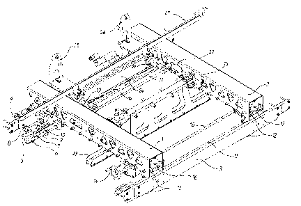
Converting press for paper or cardboard sheets including a waste stripping station and/or a blanking station with a pull-out chase (1,2,3,4) comprising a pair of horizontal transverse rails (5,11) receiving an upper stripping tool, (or a blanking tool). The first rail (5) is fixed compared to aforesaid chase and the second rail is movable in a longitudinal direction, the rails being profiled to receive and maintain in an operational waste stripping position (or blanking position), either a pull-out chase of an upper tool or an upper stripping board (or blanking board).
L'invention concerne une presse de transformation pour feuilles de papier ou de carton. Elle comprend un poste d'éjection des déchets et/ou un poste de découpage avec un châssis escamotable (1, 2, 3, 4) et deux rails transversaux à l'horizontale (5, 11) conçus pour recevoir un outil de décorticage supérieur (ou un outil de découpage). Le premier rail (5) est fixé par rapport au dit châssis et le deuxième rail est amovible dans le sens de la longueur, les rails étant profilés pour assurer la réception et le maintien du châssis escamotable d'un outil supérieur ou d'une planche de décorticage (ou d'une planche de découpage) dans une position opérationnelle d'éjection des déchets.
Note: Claims are shown in the official language in which they were submitted.
Note: Descriptions are shown in the official language in which they were submitted.
2024-08-01:As part of the Next Generation Patents (NGP) transition, the Canadian Patents Database (CPD) now contains a more detailed Event History, which replicates the Event Log of our new back-office solution.
Please note that "Inactive:" events refers to events no longer in use in our new back-office solution.
For a clearer understanding of the status of the application/patent presented on this page, the site Disclaimer , as well as the definitions for Patent , Event History , Maintenance Fee and Payment History should be consulted.
| Description | Date |
|---|---|
| Inactive: Expired (new Act pat) | 2021-05-17 |
| Letter Sent | 2021-03-01 |
| Letter Sent | 2020-08-31 |
| Inactive: COVID 19 - Deadline extended | 2020-08-19 |
| Inactive: COVID 19 - Deadline extended | 2020-08-06 |
| Inactive: COVID 19 - Deadline extended | 2020-07-16 |
| Inactive: COVID 19 - Deadline extended | 2020-07-02 |
| Inactive: COVID 19 - Deadline extended | 2020-06-10 |
| Inactive: COVID 19 - Deadline extended | 2020-05-28 |
| Inactive: COVID 19 - Deadline extended | 2020-05-14 |
| Inactive: COVID 19 - Deadline extended | 2020-04-28 |
| Common Representative Appointed | 2019-10-30 |
| Common Representative Appointed | 2019-10-30 |
| Change of Address or Method of Correspondence Request Received | 2018-03-28 |
| Grant by Issuance | 2004-11-09 |
| Inactive: Cover page published | 2004-11-08 |
| Inactive: Final fee received | 2004-08-26 |
| Pre-grant | 2004-08-26 |
| Letter Sent | 2004-08-05 |
| Notice of Allowance is Issued | 2004-08-05 |
| Notice of Allowance is Issued | 2004-08-05 |
| Inactive: Approved for allowance (AFA) | 2004-07-26 |
| Amendment Received - Voluntary Amendment | 2004-06-25 |
| Inactive: S.29 Rules - Examiner requisition | 2004-01-05 |
| Inactive: S.30(2) Rules - Examiner requisition | 2004-01-05 |
| Application Published (Open to Public Inspection) | 2001-11-16 |
| Inactive: Cover page published | 2001-11-15 |
| Inactive: First IPC assigned | 2001-07-31 |
| Inactive: IPC assigned | 2001-07-31 |
| Inactive: IPC assigned | 2001-07-31 |
| Application Received - Regular National | 2001-06-14 |
| Filing Requirements Determined Compliant | 2001-06-14 |
| Letter Sent | 2001-06-14 |
| Inactive: Filing certificate - RFE (English) | 2001-06-14 |
| Request for Examination Requirements Determined Compliant | 2001-05-15 |
| All Requirements for Examination Determined Compliant | 2001-05-15 |
There is no abandonment history.
The last payment was received on 2004-02-11
Note : If the full payment has not been received on or before the date indicated, a further fee may be required which may be one of the following
Please refer to the CIPO Patent Fees web page to see all current fee amounts.
Note: Records showing the ownership history in alphabetical order.
| Current Owners on Record |
|---|
| BOBST S.A. |
| Past Owners on Record |
|---|
| BERNARD JAQUET |
| HA-SIMON TRAN |
| JEAN-BERNARD DE DOMPIERRE |

