Language selection

Search

Patent 2347815 Summary

Third-party information liability

Some of the information on this Web page has been provided by external sources. The Government of Canada is not responsible for the accuracy, reliability or currency of the information supplied by external sources. Users wishing to rely upon this information should consult directly with the source of the information. Content provided by external sources is not subject to official languages, privacy and accessibility requirements.

Claims and Abstract availability

Any discrepancies in the text and image of the Claims and Abstract are due to differing posting times. Text of the Claims and Abstract are posted:

  • At the time the application is open to public inspection;
  • At the time of issue of the patent (grant).
(12) Patent Application: (11) CA 2347815
(54) English Title: LINE SPACER FOR POWER TRANSMISSION LINES
(54) French Title: SEPARATEUR POUR LIGNES DE TRANSMISSION D'ENERGIE ELECTRIQUE
Status: Deemed Abandoned and Beyond the Period of Reinstatement - Pending Response to Notice of Disregarded Communication
Bibliographic Data
(51) International Patent Classification (IPC):
  • H02G 07/12 (2006.01)
(72) Inventors :
  • MACKINNON, BRUCE RAYMOND (New Zealand)
  • GREGORY, OWEN ROSS (New Zealand)
(73) Owners :
  • TYCO ELECTRONICS LOGISTICS AG
(71) Applicants :
  • TYCO ELECTRONICS LOGISTICS AG (Switzerland)
(74) Agent: OSLER, HOSKIN & HARCOURT LLP
(74) Associate agent:
(45) Issued:
(86) PCT Filing Date: 1999-11-02
(87) Open to Public Inspection: 2000-05-11
Examination requested: 2004-10-08
Availability of licence: N/A
Dedicated to the Public: N/A
(25) Language of filing: English

Patent Cooperation Treaty (PCT): Yes
(86) PCT Filing Number: PCT/NZ1999/000180
(87) International Publication Number: NZ1999000180
(85) National Entry: 2001-04-24

(30) Application Priority Data:
Application No. Country/Territory Date
332618 (New Zealand) 1998-11-02

Abstracts

English Abstract


A line spacer for use between power transmission lines to maintain the lines
at a set spacing from each other includes at least two spaced jaws and a lever
action closure mechanism operable to close the jaws after engaging of the
spacer onto adjacent lines, to fix the spacer in position between the lines.


French Abstract

L'invention porte sur un séparateur destiné à être utilisé entre des lignes de transmission d'énergie électrique de façon à maintenir entre ces lignes un espacement défini. Ce séparateur comprend au moins deux mâchoires espacées et un mécanisme de blocage de l'action du levier qui ferme les mâchoires après la pose du séparateur sur des lignes adjacentes afin de le positionner entre les lignes.

Claims

Note: Claims are shown in the official language in which they were submitted.

CLAIMS:
1. A line spacer for use between lines to maintain the lines at a set spacing
from
each other, including two spaced jaw parts provided one at either end of a
spacer body
member connecting the fixed jaw parts and the two movable jaw parts slidingly
carried
by said spacer member between the fixed jaw parts, and a lever action closure
mechanism operable to slidingly move the moveable jaw parts to close the
moveable jaw
parts against the fixed jaw parts after engaging of the spacer onto adjacent
lines to fix
the spacer in position between the lines.
2. A line spacer according to claim 1 wherein the two fixed jaw parts face one
another from either end of the spacer member and the lever action closure
mechanism
operates between the two movable jaw parts to slidingly move each away from
the other
and towards the two fixed jaw parts to close the line spacer.
3. A spacer according to claim 2 wherein the lever action closure mechanism
comprises a longer member pivotally coupled at one end to one of the movable
jaw parts
and having a free end, and a shorter member pivotally coupled between a point
intermediate of the length of the longer member and the other movable jaw
part.
4. A spacer according to claim 3 including means for snap locking the free end
of
said longer member against the other of the movable jaw parts when the line
spacer is
closed.
5. A spacer according to claim 4 wherein the free end of said longer member
contains a spring snap locking mechanism.
6. A spacer according to claim 5 wherein said spring snap locking mechanism
includes a transverse protrusion on either side of the free end of said longer
member
which is spring biased towards said free end, which engages hook-shaped
recesses on
either side of said other of the movable jaw part when the drive spacer is
closed.
7. A line spacer for use between lines to maintain the lines at a set spacing
from
each other, including two spaced jaw parts provided one at either end of a
spacer body
member connecting the fixed jaw parts and the two movable jaw parts carried by
said
spacer member between the fixed jaw parts, and a lever action closure
mechanism
comprising a longer member pivotally coupled at one end to one of the moveable
jaw

parts and having a free end, and a shorter member pivotally coupled between a
point
intermediate of the length of the longer member and the other moveable jaw
part, said
lever action closure mechanism operable to move the moveable jaw parts to
close the
moveable jaw parts against the fixed jaw parts after engaging of the spacer
onto
adjacent lines to fix the spacer in position between the lines.

Description

Note: Descriptions are shown in the official language in which they were submitted.


CA 02347815 2001-04-24
WO 00/27009 PCT/NZ99/00180
LINE SPACER FOR POWER TRANSMISSION LINES
FIELD OF INVENTION
The invention comprises a line spacer typically for use between power
transmission
lines spanning between pylons, to maintain individual lines at a set spacing
from
each other.
BACKGROUND OF INVENTION
Typically such line spacers are fitted to high voltage power lines at regular
spacings
along the lines lengthwise between pylons or other line supports, to ensure
that
individual lines do not move relative to one another and touch during periods
of
high wind loading, earthquakes or similar. Typically spacers extend between
two
adjacent lines and encircle each at either end of the spacer. A triple or
larger spacer
may be used to space three or more lines from each other.
US patent 3,743,962 discloses a spacer for fitting between parallel conductors
having jaws at each end forming a conductor clamp at each end of the bar
members. The two bar members are bolted together after fitting in position
between
two conductors.
Line spacers are fitted after the lines have been strung between pylons. A
common
practice is for a workman to fit the spacers between pairs of Iines while
working
from an adjacent helicopter. This may require that the workman fits the spacer
and
then uses a spanner or other tool to close the spacer about the lines.
SUMMARY OF INVENTION
The invention provides an improved or at least alternative form of line
spacer, for
use between power transmission lines or in similar applications.

CA 02347815 2001-04-24
WO 00/27009 PCT/NZ99/00180
In broad terms the invention comprises a spacer for use between lines to
maintain
the lines at a set spacing from each other, including at least two spaced jaws
and a
lever action closure mechanism operable to close the jaws after engaging of
the
spacer onto adjacent lines to fix the spacer in position between the lines.
Preferably each pair of jaws comprises a fixed jaw part and a movable jaw part
which is slidingly moved by the lever action closure mechanism to close the
moving
jaw part against the fixed jaw part.
Preferably a twin spacer comprises two fixed jaw parts provided one at either
end of
a spacer member connecting the fixed jaw parts and two movable jaw parts
slidingly
carried by said spacer member between the fixed jaw parts. Preferably the
lever
action closure mechanism operates between the two movable jaw parts to
slidingly
move each away from the other and towards two fixed jaw parts to close the
line
spacer.
BRIEF DESCRIPTION OF THE DRAWIN~3S
A preferred form of spacer of the invention is shown in the accompanying
drawings
by way of example and without intending to be limiting, wherein:
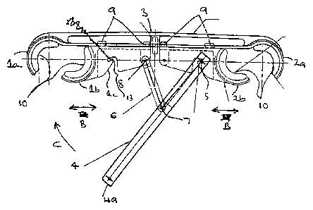
Figure 1 is the view of the preferred form spacer from one side with the
closure lever
and jaws open,
Figure 2 is a view of the preferred form spacer from one side after operating
of the
closure lever to close the spacer,
Figure 3 is a view of the closed spacer in the direction of arrow A in Figure
2, and
Figure 4 is a cross-section view of the spring loaded end of the closure Iever
in the
preferred form spacer.
2

CA 02347815 2001-04-24
WO 00/27009 PCT/NZ99/00180
DETAILED DESCRIPTION OF PREFERRED FORM
The preferred form line spacer shown in the drawings is a twin spacer intended
to
be fitted between two overhead power transmission lines, or pairs of lines, to
space
the lines from each other, and comprises two pairs of jaws generally indicated
at I
and 2 in Figure 1. The pairs of jaws comprise fixed jaw parts la and 2a
respectively,
and movable jaw parts lb and 2b. The fixed jaw parts la and 2a are carned at
either end of a spacer body member 3, on which the moving jaw parts lb and 2b
are
slidably mounted, so that the jaw parts lb and 2b may move in the direction of
arrows B during operation of a lever action closure mechanism which operates
between the jaw pairs 1 and 2.
The closure mechanism comprises closure lever 4 pivotally engaged with one of
the
movable jaw parts 2b and link 6 pivotally connected to the closure lever 4
intermediate of its length at 6 and to the other movable jaw part lb at 7. In
the
preferred form twin spacer shown the fixed jaw parts la and 2a are provided
one at
either end of the body member 3 and face each other as shown and operation of
the
lever action closure mechanism slides the two movable jaw parts lb and 2b away
from each other and towards the two fixed jaw parts to close the spacer.
The spacer body member 3 having bxed jaw parts la and 2a at either end and
mounting the moving jaw parts lb and 2b may have an I or T cross-section in
shape
and the moving jaw parts lb and 2b are mounted for sliding movement along the
member 3 by legs 9 extending around a web of the I-cross-section body member 3
as shown, so as to capture the jaw components lb and 2b on the spacer body,
while
enabling sliding movement in the direction of arrows B when the closure lever
is
moved in the direction of arrow C in Figure 1 to its closed position shown in
Figure
2.
Typically the spacer components will be formed from aluminium or other
lightweight
material. The spacer jaws mount insulating components 10 formed from rubber or
other non-conducting and preferably resilient material which when the spacer
is
closed will press tightly around the two lines as shown in Figure 2.
3

CA 02347815 2001-04-24
WO 00/27009 PGT/NZ99/00180
In use, to close the spacer after it has been fitted between two adjacent
lines so that
the lines are positioned one between each pair of jaws, the closure lever 4 is
moved
in the direction of arrow C, causing the jaw components lb and 2b to move
slidingly
away from each other towards, and to close against, the fixed jaw components
la
and 2a, so that when the spacer is fully closed, the lines will be captured
between
the two closed jaws on each side of the spacer.
Preferably the spacer includes means for snap locking the free end of the
longer
member 4 in position as shown in Figure 2 when the spacer is closed. Any
suitable
mechanism may be employed but in the preferred form and referring to Figure 4,
the distal end 4a of the lever member 4 comprises an internal bore 4b housing
a
spring 11 to one end of which is attached a bush 12. A pin 13 extends through
the
bush 12 and through slots 4c on either side of the end of the lever member as
shown. During closing the lever member 4 the pin 13 engages striker portions 1
c on
one of the movable jaw parts lb on either side, depressing the spring 11 in
the end
of the handle, and then snap locks into the hook shaped recesses 15 on either
side
as shown in Figure 2. If required for maintenance or relocation of the spacer,
the
spacer may be opened by using an L-shaped tool to depress the spring 11 and
move
the pin 13 out of recesses 15 on either side, and then pivot out the end of
the lever
member 4.
In the preferred form twin spacer described above, one jaw part moves
slidingly
towards the other jaw part to close each pair of jaws on operation of the
lever action
closure mechanism, but alternatively for example the two jaws of each pair of
jaws
may be pivotally mounted relative to one another so that operation of the
closure
lever will cause the two jaws to pivot towards each other, to close about the
lines.
Other equivalent mechanical arrangements are possible utilising a lever action
closure mechanism to enable the spacer to be closed about adjacent lines by a
lever
action in fitting of the spacer.
The preferred form twin spacer shown in the drawing is for fitting between two
lines
and for example a triple spacer may include three pairs of jaws intended to
enable
4

CA 02347815 2001-04-24
WO OO/Z7009 PCT/NZ99/00180
fitting of the spacer to three adjacent lines, with two similar lever action
closure
mechanisms provided one between each pair of jaws. A quadruple spacer for
fitting
between four adjacent lines may comprise four pairs of closable jaws and three
lever
action closure mechanisms between each jaw pair, and so on.
The foregoing describes the invention including a preferred form thereof.
Alterations
and modifications as will be obvious to those skilled in the art are intended
to be
incorporated within the scope hereof as defined in the accompanying claims.
5

Representative Drawing
A single figure which represents the drawing illustrating the invention.
Administrative Status

2024-08-01:As part of the Next Generation Patents (NGP) transition, the Canadian Patents Database (CPD) now contains a more detailed Event History, which replicates the Event Log of our new back-office solution.

Please note that "Inactive:" events refers to events no longer in use in our new back-office solution.

For a clearer understanding of the status of the application/patent presented on this page, the site Disclaimer , as well as the definitions for Patent , Event History , Maintenance Fee  and Payment History  should be consulted.

Event History

Description Date
Application Not Reinstated by Deadline 2008-11-03
Time Limit for Reversal Expired 2008-11-03
Deemed Abandoned - Failure to Respond to Maintenance Fee Notice 2007-11-02
Inactive: Abandoned - No reply to s.30(2) Rules requisition 2007-10-23
Inactive: S.30(2) Rules - Examiner requisition 2007-04-23
Letter Sent 2004-10-26
Request for Examination Received 2004-10-08
Request for Examination Requirements Determined Compliant 2004-10-08
All Requirements for Examination Determined Compliant 2004-10-08
Letter Sent 2001-12-06
Inactive: Single transfer 2001-10-26
Inactive: Courtesy letter - Evidence 2001-09-25
Inactive: Single transfer 2001-08-03
Inactive: Cover page published 2001-07-24
Inactive: First IPC assigned 2001-07-15
Inactive: Courtesy letter - Evidence 2001-07-10
Inactive: Notice - National entry - No RFE 2001-07-04
Application Received - PCT 2001-06-18
Application Published (Open to Public Inspection) 2000-05-11

Abandonment History

Abandonment Date Reason Reinstatement Date
2007-11-02

Maintenance Fee

The last payment was received on 2006-10-20

Note : If the full payment has not been received on or before the date indicated, a further fee may be required which may be one of the following

  • the reinstatement fee;
  • the late payment fee; or
  • additional fee to reverse deemed expiry.

Patent fees are adjusted on the 1st of January every year. The amounts above are the current amounts if received by December 31 of the current year.
Please refer to the CIPO Patent Fees web page to see all current fee amounts.

Fee History

Fee Type Anniversary Year Due Date Paid Date
Basic national fee - standard 2001-04-24
Registration of a document 2001-08-03
MF (application, 2nd anniv.) - standard 02 2001-11-02 2001-09-27
MF (application, 3rd anniv.) - standard 03 2002-11-04 2002-10-01
MF (application, 4th anniv.) - standard 04 2003-11-03 2003-09-26
Request for examination - standard 2004-10-08
MF (application, 5th anniv.) - standard 05 2004-11-02 2004-10-25
MF (application, 6th anniv.) - standard 06 2005-11-02 2005-10-28
MF (application, 7th anniv.) - standard 07 2006-11-02 2006-10-20
Owners on Record

Note: Records showing the ownership history in alphabetical order.

Current Owners on Record
TYCO ELECTRONICS LOGISTICS AG
Past Owners on Record
BRUCE RAYMOND MACKINNON
OWEN ROSS GREGORY
Past Owners that do not appear in the "Owners on Record" listing will appear in other documentation within the application.
Documents

To view selected files, please enter reCAPTCHA code :


To view images, click a link in the Document Description column (Temporarily unavailable). To download the documents, select one or more checkboxes in the first column and then click the "Download Selected in PDF format (Zip Archive)" or the "Download Selected as Single PDF" button.

List of published and non-published patent-specific documents on the CPD .

If you have any difficulty accessing content, you can call the Client Service Centre at 1-866-997-1936 or send them an e-mail at CIPO Client Service Centre.

({010=All Documents, 020=As Filed, 030=As Open to Public Inspection, 040=At Issuance, 050=Examination, 060=Incoming Correspondence, 070=Miscellaneous, 080=Outgoing Correspondence, 090=Payment})


Document
Description 
Date
(yyyy-mm-dd) 
Number of pages   Size of Image (KB) 
Representative drawing 2001-07-22 1 13
Description 2001-04-23 5 200
Claims 2001-04-23 2 68
Abstract 2001-04-23 1 58
Drawings 2001-04-23 1 42
Reminder of maintenance fee due 2001-07-03 1 112
Notice of National Entry 2001-07-03 1 194
Courtesy - Certificate of registration (related document(s)) 2001-12-05 1 113
Reminder - Request for Examination 2004-07-04 1 117
Acknowledgement of Request for Examination 2004-10-25 1 177
Courtesy - Abandonment Letter (Maintenance Fee) 2007-12-30 1 175
Courtesy - Abandonment Letter (R30(2)) 2008-01-01 1 167
Correspondence 2001-07-03 1 24
PCT 2001-04-23 12 452
Correspondence 2001-09-24 1 22