Note: Descriptions are shown in the official language in which they were submitted.
CA 02347859 2001-04-24
WO 00!28318 PCT/GB99/03726
APPARATUS A.ND METHODS RELATING TO HUMIDIFIED AIR
AND TO OLFACTORY MONITORING
The present invention relates in a first aspect to an apparatus for and a
method
of providing a flow of humidified air having a selected humidity level. In a
second
aspect the invention relates to a method of and apparatus for monitoring one
or more
parameters or components of a sample gas or vapour. In a preferred form the
present
invention relates to the monitoring of an exhalation of a subject such as an
animal or
bird in order to provide information about the subject. The information can
relate to
health, diet or other condition. The subject can be a farm livestock animal
such as a
cow, or a domestic animal such a cat, dog or horse. The subject could also be
a turkey
or chicken.
Animals produce exhalations some of which are odours such as those from the
skin, breath, milk and solid and liquid waste products. The term exhalation
includes
not only breath expelled by a subject, but also any emanation of gas or vapour
derived
from the subject. Exhalation includes breath from an animal, vapour from milk
or any
other volatile materials emanating from the animal. The condition of the
animal can
be determined from a component of the exhalation, which component may be an
odour or specific compound or other material. The composition of such an
exhalation
can provide a valuable source of information regarding the animals state of
health.
However it is to be appreciated that in its first aspect the invention relates
broadly to apparatus for providing humidified air, and may be used in any
application
where humidified air is required. Similarly in its. second aspect the
invention relates
to measuring one or more parameters or components of any sample gas or vapour.
2S The invention in its second aspect embraces the use of any sensor whose
performance
is affected by humidity. Examples of such sensors are olfactory sensors as
used in a
so called "electronic nose'', and infrared absorption spectrum sensors. Other
types of
sensors which are affected by humidity will be apparent to those skilled in
this art.
~U$$'~'I"ttJ~ SHEET (~Ut.E 2~
CA 02347859 2001-04-24
WO 00/28318 PCTIGB99103726
The use of the invention in monitoring animal exhalation samples is merely a
preferred application of the invention.
Examples of "electronic noses" may be found in GB-A-2 272 773 (British
Technology Group Limited), US-A-4 202 352 (Osborne:), and EP-A-0 650 051
(Kyoto
Dai-Ischi Kagaku Co., Ltd.). The olfactory sensors may be arranged to create
as an
output, patterns which give a "finger print" of the odour being analysed. The
sensors
utilised in the present invention may be of the kind described in a paper
entitled
"Mufti Element Arrays for Sensing Volatile Chemicals'" by Krishna C. Persaud
and
Paul Travers, Intelligent Instruments Computers, JulyLAugust I 991, or other
devices
IO subsequently developed. The paper referred to gives an overview of the
types of
olfactory sensors available, and the principles of operation thereof.
A main problem which has been found in the use of an electronic nose, and in
the use of infrared sensors for analysing gas/vapour components, is that the
sensors
are extremely sensitive to variations in humidity of the sample. The human or
animal
I S nose operates in a controlled humidity environment, in that the receptors
are
positioned under a layer of mucus, so that odours which are sensed penetrate
through
a mucus layer. This keeps the human or animal sensors at a stable humidiri~.
Although attempts have been made in the use of electronic noses to supply the
sample
at a standardised humidity, this has in practice not been controlled
sufficiently
20 accurately. It is often found that an apparently strong signal detected by
the electronic
nose can be attributed mainly to a change in humidity between a flushing gas,
without
odour, used for calibration, and a test sample, where the humidity has been
increased
due to the presence of the sample. Put simply, the ;presence of a genuine
"finger
print" of an odour, is swamped by a change in humidity during the analysing
and
25 measurement of the sample.
Returning to consideration of the first aspect of the invention, attempts have
been made previously to supply humidif ed air having a selected predetermined
humidity, but these have been provided by mixing together a dry air stream and
a wet
air stream in accordance with predetermined ratios, which have been previously
tested
-2-
CA 02347859 2001-04-24
WO 00/28318 PCTIGB99/03726
against a resulting humidity, and which are supposed therefore to reproduce
that level
of humidity.. Essentially previous commercially available apparatus for
providing
humidified air at a selected humidity level have merely operated by the
electronic
equivalent of "look-up tables", without any accurate monitoring and adjustment
to
ensure that the output humidified air stream is at the required level of
humidity.
In accordance with the first aspect of the invention, it is an object of the
invention to provide apparatus for providing humidified air at a selected
level of
humidity of greater accuracy and stability than has pre~riously been possible.
In the
second aspect of the invention, it is an object of the invention to provide a
more
accurate and dependable apparatus and method for monitoring parameters or
components of a sample. for example an exhalation of an animal.
In WO 97/00444 (British Technology Group Limited) there is disclosed
apparatus for monitoring animal exhalation, to provide an indication of the
condition
of an animal. In one arrangement, the animal exhalation is pumped to a mixing
I5 chamber in which it is combined with a stream of humidified air and the
mixture is
then pumped to a sensing chamber including a sensor array. The stream of
humidified
air is obtained from air passing from a humidifier and a dryer, the streams
being
combined together in a valve which controls the relative proportions of dried
and
humidif ed gas reaching the mixing chamber. The temperature and humidity of
the
sample in the sensing chamber is monitored by temperature and humidity
sensors.
In accordance with the invention in a first aspect there is provided apparatus
for providing a flow of humidified air having a selected humidity level,
comprising:
supply means for supplying a first air stream and a second air stream to be
combined together, the second air stream having a higher humidity than the
first air
stream,
a humidity sensor for sensing the humidity of air combined from the first and
second air streams, and
-3-
CA 02347859 2001-04-24
w0 00/28318 PCT/GB99103726
contral means for varying the proportions in which the first and second air
streams are combined in response to a humidity level signal from the humidity
sensor
so as to maintain the humidity of the combined air at a selected humidity.
In a particularly preferred form, the supply means comprises input means for
supplying an input stream of air, and a controllable valve far directing air
from the
input means to a first air flow path and to a second air flow path, the second
air flow
path including humidifying means for increasing the humidity of the air in the
second
air flow path, and the valve being controllable to vary the amount of air
directed to
each of the air flow paths. the control means being an~anged to control the
valve in
response to said humidity level signal from the humidity sensor so as to
maintain the
humidity of the combined air at a selected humidit~~.
The controllable valve may comprise a proportional. analogue valve. in which
the input stream of air is divided and directed partly into the first air flow
path and
partly into the second air flow path. the controllable valve varying the
proportions of
air directed into the two paths. However it is preferred that the controllable
valve is a
multistate valve, for example a two way valve, in which the whole of the input
air
flow is directed to one of the air flow paths at any one time. Preferably the
controllable valve has a first state arranged to direct the entire input
stream of air to
the first air flow path and a second state arranged to direct the entire input
stream of
air to the second air flow path, the control means beinf: arranged to switch
the valve
between states and to vary the time periods of the two states to achieve the
variation in
proportion in which the first and second air streams are combined.
Conveniently the humidifying means in the second air flow path comprises
means for contacting the air stream with water, for exarr~pie by bubbling the
air stream
through water. It is found that this introduces a greater resistance to flow
through the
second air flow path than through the first. In accordance with a further
feature of the
invention the first air flow path includes a flow restrictor. In some
arrangements the
flow restrictor is variable, over a range including a restriction sufficient
to balance the
air flows in the first and second air flow paths. In other arrangements the
flow
-4-
CA 02347859 2001-04-24
WO 00/28318 PCT/GB99103726
restrictar is a fixed restrictor, introducing an air flow restriction
approximately equal
to the air flow restriction introduced by the humidifying means in the second
air flow
path.
The provision of the flow restrictor is particularly advantageous in
arrangements where the controllable valve is a multistate device as set out
above. If
the restrictor is not present, it may be found that the controllable valve is
set by the
control means to be predominantly in the second state, with occasional supply
through
the frst air flow path. Such a situation can produce irregular operation of
the
humidity sensor due to the effect of a sudden substantial air flow from the
first air
flow path. Consequently, it is preferred that the air flow restrictor has a
fixed value,
or is adjusted to a value. such that the time periods of the valve in the two
states are of
the same order of magnitude, for example to differ from each other by no more
than a
multiple of two, when the humidity sensed by the humidity sensor is close to a
required level set by the control means: Preferably the arrangement is such
that the
time periods in the two states are approximately the sa.n~e. Although the
combination
of the two air streams may be made in a number of different arrangements, for
example in a conduit. it is preferred that there is provided a mixing vessel
connected
to receive air from the first air stream and the second air stream only, the
mixing
vessel having an outlet for supplying combined air to further apparatus, and
the
humidity sensor being mounted to sense the humidity of air in the mixing
vessel.
Conveniently the said control means comprises a microprocessor connected to
receive the said humidity level signal from the humidity sensor. The control
means
may include a proportional integral differential controller for controlling
the valve in
response to the said humidity level signal from the humidity sensor.
In a particularly preferred application of this aspect of the invention. there
is
provided an assembly for monitoring one or more olfactory parameters of a
sample
placed in a sensor chamber including one or more ollfactory sensors, for
example an
array of sensors for producing a profile -of the odour of a sample placed in
the
-5-
CA 02347859 2001-04-24
WO 00128318 PCT/GB99I03726
chamber. In such an arrangement the assembly may include apparatus for
providing a
flow of humidified air, such as has been set out in previous paragraphs.
It is to be appreciated that where features of the invention are set out
herein
with regard to apparatus according to the invention in this aspect, such
features may
also be provided with regard to a method according to thc~ invention, and vice
versa.
In particular, there is provided in accordance with the invention a method of
providing humidified air comprising:
supplying a first air stream and a second air stream, the second air stream
having a higher humidity than the first air stream,
combining air from the two air streams,
sensing the relative humidity of the combined air, and
varying the proportions in which tile first and second air streams ate
combined
in response to the said sensed humidity of the combined air, in such a manner
as to
maintain the humidity of the combined air at a selected humidity.
In a particularly preferred arrangement, the method includes supplying
an input air stream to a controllable valve for directing air from the input
air stream to
a first air flow path and to a second air flow path, the valve being
controllable to vary
the amount of air directed to each of the air flow paths, increasing the
humidity of the
air in the second air flow path, and controlling the valve :in response to the
said sensed
humidity of the combined air, in such a manner as to maintain the humidity of
the
combined air at a selected humidity.
A second aspect of the invention is concerned with the monitoring of one or
more components or parameters, e.g. olfactory parameters, of a sample gas or
vapour.
In accordance with this aspect of the invention there is provided a method of
monitoring one or more components or parameters of a sample gas or vapour
comprising the steps of
measuring the humidity of the sample gas or vapour, e.g. in a sample chamber,
providing a sensor chamber containing one or more sensors, e.g. olfactory
sensors,
-6-
CA 02347859 2001-04-24
WO 00/28318 PCT/GB99103726
adjusting the humidity in the sensor chamber to be the same as the measured
humidity of the sample gas or vapour,
admitting into the sensor chamber the sample gas or vapour at the same
humidity level as the air in the sensor chamber, and
monitoring the output of the sensor or sensors.
Preferably, a flow of humidified air at a selected level of humidity is
provided,
in which case this flow of humidified air is passed through the sensor
chamber.
In a preferred form. the step of providing a supply of humidified air in the
sensor chamber comprises generating a stream of humidified air from apparatus
including a first humidity sensor for sensing the humidity of the air
generated, and
control means operable to vary the humidity of the generated air supply and to
adjust
the humidity of the output air supply to be equal to a predetermined humidity
level
entered into the control means. The humidifed air stream may be provided by
the
steps of the method of the first aspect of the invention, as set out above.
Conveniently the step of adjusting the humidity in the sensor chamber includes
measuring the humidity in the sensor chamber by a second humidity sensor, and
varying the humidity of the said supply of humidified air until the humidity
levels
measured on the f rst and second humidity sensors are the same as the said
measured
humidity of the sensor chamber. Also convenientliy the step of measuring the
humidity of the sample gas or vapour in the sample chamber is carried out by
use of a
third humidity sensor mounted for measuring the humidity in the sample
chamber.
It is to be appreciated that where features of the invention in the second
aspect
are set out herein with regard to a method according to the invention, such
features
may also be provided with regard to apparatus according to the invention, and
vice
versa.
In particular there is provided in accordance with the invention apparatus for
monitoring one or more olfactory parameters of the sample gas or vapour
comprising
optionally, a sample chamber for a sample gas or vapour,
means for measuring the humidity of the sample gas or vapour,
..
CA 02347859 2001-04-24
WO 00!28318 PCT/G899/03726
apparatus for providing a flow of humidified air having a selected level of
humidity,
a device for passing humidified air through a sensor chamber containing one
or more sensors, at a selected level of humidity such that the humidity in the
sensor
j chamber is adjusted to be the same as the measured humidity of the sample
gas or
vapour,
a valve, which may also constitute the device for passing humidified air
through the chamber, for admitting into the sensor chamber the sample gas or
vapour
at the same humidity level as the air in the sensor chamber for monitoring of
one or
more components or parameters by the sensor or sensors.
Embodiments of the invention will now be described by wav of example with
reference to the accompanying drawings in which:-
Figure 1 is a block circuit diagram of apparatus for providing a flow of
humidified air having a selected humidity level, embodying the present
invention in
I 5 its first aspect;
Figure 2 is a block circuit diagram of apparatus for monitoring one or more
olfactory parameters of a sample gas or vapour, embodying the invention in its
second
aspect, the apparatus being shown with various valves in positions allowing
flushing
and purging of the apparatus;
Figure 3 shows the block circuit diagram of Figure 2, but with the various
valves set in positions to allow loading of a sample;
Figure 4 shows the block circuit diagram of Figure 2, but with the various
valves set in positions to allow odour sampling;
Figure 5 shows the block circuit diagram of F~ figure 2, but with the various
valves set in positions to allow odour reading;
Figure 6 shows the block circuit diagram of Figure 2, but with the various
valves set in positions to allow reading of parameters during sensor decay;
Figure 7 is a flow chart illustrating the operation of the embodiment shown in
Figures 2 to 6;
_g_
CA 02347859 2001-04-24
WO 00/28318 PCT/GB99/0372b
Figure 8 is a representation of the appearance on a monitor screen of an
output
trace from sensors of the embodiment of Figures 2 to T, showing the readings
during
introduction of the sample gas or vapour into the sensor chamber;
Figure 9 is a representation of the appearance on a monitor screen of an
output
trace from sensors of the embodiment of Figures 2 to 7, showing decay of the
readings
of the olfactory sensors as the sample gas or vapour exits from the sensor
chamber;
and
Figure 10 is a schematic diagram of a further embodiment according to the
second aspect of the invention.
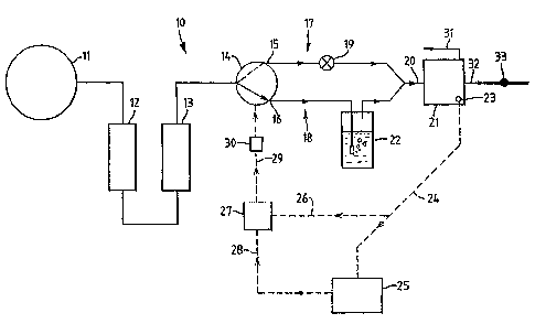
Figure 1 shows apparatus embodying the invention for generating a flow of
humidified air having a selected level of humidity. The: generator 10 has at
its inlet a
pump 11 for drawing ambient air into the apparatus. A purification column 12
is
connected to the output of the pump 1 l and passes the air stream to a drying
column
13 the outlet of which is joined to a two-way solenoid valve 14 having first
and
second outlets 15 and 16. The outlet 15 forms part of a first air flow path
indicated
generally at 17 and the second outlet 16 fornis part of a second air flow path
18. The
outlet 15 is connected to a variable flow restrictor or regulator 19 the
output of which
is connected to a common conduit 20 leading to a mixing vessel 21. The second
outlet 1 b is connected to the common conduit 20 through a humidifying means
22
which may be a frit submerged in water in a stainless bubbler chamber where
the air
flow is saturated with water vapour before entering the mixing vessel 21.
Mounted on the mixing chamber 21 is a humidity sensor which may comprise
a relative humidity rH probe 23. This constitutes a fis°st relative
humidity sensor of
the various embodiments of the invention. The output of the rH sensor 23 is an
electrical signal representing the humidity level in the mixing vessel 21. The
relative
humidity sensor 23 is connected by data transfer line 24 to a microprocessor
25. The
humidity level signal is also passed from the rH sensor ;Z3 along a data
transfer line 26
to a proportional integral differential controller PID 27. The PID controller
also
receives an input along a line 28 from the microproces;>or 24. The input
signal along
-9-
CA 02347859 2001-04-24
WO 00/28318 PCT/GB99I03726
the line 26 is a signal representing the current humiidity level signal from
the rH
sensor 23. The signal along the line 28 is a set humidity level signal which
sets fox
the PID controller the target level for the humidity in the mixing vessel 21.
The output of the PID controller 27 is a control signal passing along a line
29
from the PID controller via a relay 30 to the control input of the valve 14.
Valve 14 is
a controllable two-way valve such that the valve can switch the input air
stream from
the column I3 rapidly between the first and second air flow paths 17 and 18.
The
controllable valve 14 has a first state arranged to direct. the input air
stream to the first
air flow path entirely, and a second state arranged to direct the entire input
stream to
I0 the second air flow path entirely. The PID controller 27 is arranged to
switch the
valve between states and to vary the time periods of the two states to achieve
the
variation in proportion in which the first and second air stream are combined.
The
mixing vessel 21 has a bleed to atmosphere at 31 and has an output conduit at
32 from
which humidified air may be passed to further operating companents.
The operation of the embodiment is as follows.. Room air is pumped through
the purification column 12, conveniently of activated carbon, by the diaphragm
pump
11 operating at for example 600m1/min. The resulting clean air passes through
a
drying column 13 to give a stream of clean dry air. This then passes through
the two-
way solenoid valve under the control of the PID controller 27. The valve 14
splits the
air flow, one stream passing directly to the mixing chamber through a flow
control
valve and the other passing through the humidifier 22 before reaching the
mixing
chamber 21. The relative humidity probe 23 in the mixing chamber measures the
humidity of the mixed streams and feeds the result t:o the microprocessor 25.
Any
desired set point is set on the microprocessor, using in-house software, and
is then fed
to the PID controller 27. The PID controller 27 proportions the wetldry air
flows to
allow rapid ramping between set humidities without overshoot. Feedback from
the rH
probe 23 in the mixing chamber allows precise control of the generated
humidity, and
it is this closed loop feedback to the PID controller :?7, related to the
actual relative
humidity produced by the apparatus at the mixing vessel ? 1, that gives
substantial
-10-
CA 02347859 2001-04-24
WO 00128318 PCT/GB99/03726
improvement in control over previous rH generators vvhich employed an open
loop
control to determine the wet/dry ratio required to give a desired humidity.
The flow controller 19 in the dry air flow allows the flow rate of the wet and
dry streams to be balanced to smooth the pulses of air entering the mixing
chamber.
The output of the humidity generator is then fed on to further components, via
a
solenoid valve 33. To avoid pressure build-up when this valve is stmt, the
mixing
chamber is vented to atmosphere through the conduit 31. To avoid pressure
build-up
when this is shut, the mixing chamber is vented to the atmosphere through the
bleed
conduit 31.
The operation of the PID controller 27 is such that when a rapid change is
required between the set humidity level and the humidity level detected by the
rI-1
sensor 23, the valve 14 is switched to rive longer periods in. say, the second
state with
the air flow directed to the second air flow path 18. Thus the PID controller
switches
the valve 14 between the two states back and forth. during romping, but leaves
the
1 ~ valve mainly in one or other state.
As the humidity of the air approaches the; set humidity. it is found
advantageous to have the valve 14 switch back and forth between the two states
with
time periods which are approximately the same, and in any case not differing
from
each other more than, say, by a factor of two. It is for this reason that the
variable
flow restrictor 19 is inserted in the first air flow path. If this air
restrictor is not
present, it is found that the additional resistance provided in the second air
flow path
by the humidifier 22, farces a situation where the valve 14 is held for a
lengthy period
in the second state while the wet air stream is fed to the mixing valve
followed by a
shorter period when fixed to the f rst state. Because of the lesser resistance
in the first
air flow path, sufficient dry air is provided in a short period burst,
compared with the
slower long period in the second state. This is found disadvantageous because
the rH
sensor 23 reacts strongly to the blast of dry air, and the PID controller
overreacts in
controlling the valve 14. The result is -an overshoot when approaching the
desired
stable situation when the humidity level sensed at tJhe sensor 23 is equat to
the
CA 02347859 2001-04-24
WO 00/28318 PCT/GB99103~26
humidity Level set along the .line 28. To avoid this overshoot, the flow
restrictor 19
can be variable, and can be adjusted until the periods in the two states are
approximately the same at approach to the set humidity, or a fixed restrictor
can be
used selected at the appropriate value.
Figure 2 shows a block circuit diagram of appa~~atus embodying the invention
for monitoring a number of olfactory parameters of a sample gas or vapour, so
as to
provide a "finger print" of the odour from the sample. In the preferred form
described, the apparatus utilises the output of the humidified air generator
shown in
Figure 1, the output from the valve 33 in Figure I being provided along a
conduit 34
l 0 in Figure 2. The principal components of the apparatus shown in Figure 2
are a solid
or liquid sample chamber 35 for containing a sample giving rise to the gas or
vapour
to be analysed: an odour chamber 49 din effect a i~urther sample chamber). for
containing gas or vapour from the solid or liquid sample in the chamber 35: a
sensor
chamber 36 in which are positioned an array of olfactory sensors for measuring
various parameters of the gas or vapour from the sample; and a series of
valves for
switching air flows between the components, for flushing, sensing and other
operations.
The input conduit 34 is connected to a first valve 37 for use during humidity
level setting and the decay phase of sensing, and a se<:ond valve 38, for use
during
flushing. A purge gas conduit 39 is available for feeding purge gas to a
third, purge
valve 40 the outlet of which is combined with the outlet. of the flush valve
38, both of
which are connected via a conduit 41 to a first port 42 of a six port valve
43. The
conduit 41 is also connected to a frst port 70 of a first, four port valve 44.
A second
port 45 of the six port valve 43 is connected to a fourth port 46 of the four
port valve
44. A third port 47 of the four part valve 44 is connected to an input 48 of
the odour
chamber 49. An outlet of the odour chamber 49 is canneeted via a conduit 50 to
a
third port 51 of a second, four port, B, valve 52. A second port 53 is
connected along
a conduit 54 to the sensor chamber 36: the outlet of which is connected along
a
conduit 55 to a fourth valve 56 leading to atmosphere. The sensor chamber 36
has
-12-
CA 02347859 2001-04-24
WO 00/28318 PCTlGB99103726
mounted therein a second humidity sensor 57. The odour chamber 49 has a third
humidity sensor 58 mounted therein.
A second port 59 of the first, A valve 44, is connected along a conduit 60 to
a
pump 61, the outlet of which is connected along conduit 62 to a fourth port 63
of the
second, B valve 52. A first port 64 is connected along a conduit 65 to the
outlet of the
humidity level/decay phase valve 37. A one-way valve 66 is connected between
the
conduits 6~ and 71, in a direction to allow gas from the conduit 71 to pass to
the
conduit 65, when the vent valve 56 is closed
The operation of the apparatus can be divided into five main stages,
corresponding to Figures 2 to 6. In Figure 2 during 'the flush and purge
stage. the
valve positions are as follows.
Humidity Level/Decay Phase Valve ahut
37
Flush Valve 38 t~pen during flushing
Purge Valve 40 t~pen during purging
Vent Valve 56 ~Qpen
Muitiport Valves 43, 44 and 52 t~onnections made between
ports as shown in the
Figure.
in Figure 3 during the sample loading stage. the valve positions are as
follows.
Humidity Level/Decay Phase Valve :3hut
37
Flush Valve 38 ohut
Purge Valve 40 ;3hut
Vent Valve 56 ;shut
Multiport Valves 43, 44 and 52 (connections made between
ports as shown in the
Figure.
In Figure 4 during odour samplingw and humidity level setting, the valve
positions are as follows.
-13-
CA 02347859 2001-04-24
WO 00128318 PCT/GB99/037Z6
Humidity Level/Decay Phase Valve Open
37
Flush Valve 38 Shut
Purge Valve 40 Slhut
Vent Valve 56 Open
Multiport Valves 43, 44 and 52 Connections made between
ports as shown in the
Figure.
In Figure 5 during odour reading, the valve positions axe as follows.
Humidity Level/Decay Phase Valve Shut
37
Flush Valve 38 Shut i
Purge Valve 40 Shut
Vent Valve 56 Shut
Multiport Valves 43, 44 and 52 Connections made between
ports as shown in the
Figure.
In Figure 6 during sample decay reading, the valve positions are as follows.
Humidity Level/Decay Phase Valve Open
37
Flush Valve 38 Shut
Purge Valve 40 Open
Vent Valve 56 Shut
Multiport Valves 43, 44 and 52 Connections made between
ports as shown in the
Figure.
The operation of the apparatus will now be described with reference to Figures
I O 2 to 6. With reference to Figure 2, the system 36 is first cleaned by
flushing with 70%
humidified air, the valve 3$ being open. The pump 6I pumps the flushing gas
through the chambers 35, 49 and 36 and out through the vent valve 56 to
atmosphere.
-I4-
CA 02347859 2001-04-24
WD 00128318 PCTlGB99103726
Referring to Figure 3, the sample to be tested is then introduced into the
sample chamber 35 on a stainless steel spatula. After a settling time the
humidity of
the sample is measured by the third relative humidity sensor 58 with the
valves
positioned as in Figure 3.
Referring to Figure 4, at this stage the gas or vapour from the sample in the
sample chamber 35 is introduced into the odour chamber 49 and the pump 61
circulates gas around the circuit shown in Figure 4 until the humidity of the
sample
gas measured by the third humidity sensor 58, has stabilised. The required
humidity
level as measured from the third humidity sensor 58 is then set in the
apparatus of
Figure 1 by the microprocessor 25 and the humidified air generator of Figure 1
is
operated until the required humidity is reached and has settled. During this
period, the
output stream of air from the apparatus of Figure 1 enters along the input
conduit 34,
through the open valve 37, through the sensor chamber 36, and is vented to
atmosphere through the valve 56. The arrangement of Figure 4 continues until
the
readings on three humidity sensors are the same, than is to say the first
humidity
sensor 23 in Figure 1, and the second and third humidity sensors 57 and 58 in
Figure
4.
With the valve settings as shown in Figure 5, the sample chamber 35 is
isolated and the pump 61 circulates air from the odour .chamber 49 through the
sensor
chamber 36, and back through the one-way valve 66 to the pump 6I. During this
stage, the response of the sensors is recorded as this changes from the steady
state
(Figure 4) whilst the humidified air from the conduit 34 passes through the
sensor
chamber, without sample odour, to the part of the cycle shown in Figure 5,
when the
odour is circulating through the sensor chamber. Figure 8 is a representation,
of the
appearance of the rH generator control software screen during the flush stage
of the
cycle. Figure 9 is the appearance of the screen during "purge". In Figures 8
and 9,
the plots are labelled with reference numerals corresponding to the respective
humidity sensors 23, 57, 58. The traces of Figures 8 and 9 are representations
of the
-I5-
CA 02347859 2001-04-24
WO 00/28318 PCT/GB99/03726
appearance of the PC monitor at various stages through the sample cycle, and
show
the output from rH probes 1, 2 and 3 during these phase s.
Finally, further information can be obtained from the sensor decay response,
that is to say the falling signal recorded by the sensors when the odour
chamber is
isolated from the sensor chamber, and the presence of l:he odour gradually
dies away
as the sensor chamber is traversed by the humidified air flow from the
generator
shown in Figure I . Therefore, with the valve settings as. shown in Figure 6.
the sensor
responses continue to be recorded as the odour is flusl-~ed out of the sensor
chamber
through the open valve 56. An example of the sensor response during decay is
shown
in Figure 9.
The purpose of the series of stages shown in Figures 2 to 6 is to obtain the
balanced humidity situation shown in Figure 4, just before the two four port
valves are
simultaneously moved to the position shown in Figure S. In this balanced
position the
relative humidity levels are the same at the three humidity sensors. The
importance of
this is that when the valves 44 and 52 are moved together to the position
shown in
Figure 5, there is no drastic change in the humidity Level associated with the
introduction of the odour into the sensor chamber. This means that the sensor
responses shown in Figures 8 and 9 are principally clue to the introduction of
the
odour, and are not unduly influenced by a sudden change in humidity in the
sensor
chamber. It has been found that in the absence of balancing the relative
humilities
before introducing the odour, most of the change recorded by the olfactory
sensors
can be attributed to the change in humidity rather than to the introduction of
the
odour. Since the finger print of the odour depends upon the relatively small
differences between the responses of the different sensors by the three
different curves
on the graph, it will be appreciated that these differences are easily lost if
they are
superimposed on a change of signal level several magnitudes larger, produced
by a
change of humidity. This does not occur in accordance with the preferred
embodiment of the invention. if the humilities are balanced throughout the
system
before the odour is introduced into the sensor chamber.
-'16 -
CA 02347859 2001-04-24
WO 00/28318 PCT/GB99/03726
In Figure 7 there is shown a flow chart representing the steps which have been
explained with reference to Figures 2 to 6. Considering briefly Figure 7, the
boxes
and flow lines correspond to the steps which have been described approximately
as
follows. At the start box 100 the operator switches on the microprocessor
which
shows on the screen a reminder at box 101 to fill the humidifier. At box 102 a
settling
time is set to allow the humidity sensors to settle. At step 103 the operator
sets the
valve positions as shown in Figure 2, for the flush cycle to commence. At box
104 a
further settling time is allowed until rHl = set flush rI-l. When this has
been achieved.
at box I OS (decision box in program. "iflthen"), the operator changes the
position of
the valves A and B to that shown in Figure 2.
At box 106, the operator carries out the flushing cycle described with
reference
to Figure 2, by flushing the humidified air through components 35, 36. 49 plus
pipework plus valves. At box 107, the purging cycle; described with reference
to
Figure 3 is carried out, purged gas being passed through components 35, 36, 49
plus
intervening pipework.
At box I08, the operator sets into the microprocessor 2~ in Figure 1 the
required background humidity level. At decision box 109 a further waiting time
occurs until the humidity levels at humidity sensors ~8 and 23 (Figure I)
become
equal.
When this is achieved, at box 110. the operator changes simultaneously the
settings of valves 44 and 52 to the position in Figure 4. At box 111 the
operator
enters a description of the sample into the microprocessor for printing out on
the
results sheet. At box 112 the sample is inserted into the sample chamber, and
at 113
the pump 61 is switched on.
At box 114 the humidity level at the sensor 58 in the odour chamber 49 is read
and is then entered at box 115 into the microprocessor25 (Figure 1) to be set
into the
PID controller 27. At box 116 there is a further settling time until the
humidity levels
at humidity sensor 23 reaches that at sensor 58. At box 117 the sensor
equalibralising
step takes place, which consists of humidified air passing from the generator
through
_17_
CA 02347859 2001-04-24
WO 00/28318 PCT/GB99103726
chamber 36 until sensors 58, 57, 23 all read the same. At box 118 there is a
further
settling time until the humidity levels of all three sensors 23, 58 and 57
become equal.
When this is achieved, at box I 19 the operator changes simultaneously the two
four
port valves 44 and 52 from the positions shown in Figure 4 to the positions
shown in
Figure 5.
At box I20 the microprocessor reads and notes the outputs of the olfactory
sensors, and this is done at step 121 repeatedly until the: data collection is
complete.
When this is achieved, at box 123 the valves 44 and 52 are changed
simultaneously to
the positions shown in Figure 6. The outputs of the olfactory sensors are then
read
again at boxes 124 and 12~ until the sensor decay readinl;s are complete. When
this is
done the sample is removed, at box 126, and if required the cycle is then
recommenced at box 103.
An alternative embodiment is shown in schematic form in Figure 10, This is a
simplified arrangement which omits the mixing chamber and may omit the sample
chamber. A different type of sensor is used, namely an infrared absorption
spectrum
sensor. In this case the apparatus is designed fox the detection of acetone in
cow's
breath - an indicator of ketosis.
Apparatus. developed by one of the inventors of the present invention, is
available for collecting a sample of cow's breath when the cow is in a stall.
This is
described in WO-A-9907216. With this apparatus it is possible to collect a
series of
exhalations from a cow's lungs and store them temporarily. The sampling
apparatus
described here may then be used to analyse the stored e:Khalation for acetone
or other
compounds.
The apparatus comprises an inlet 200 for cow breath, which is drawn in by the
action of a pump 201 and exhausted from outlet 202. Between the inlet 200 and
the
pump 201 and outlet 202 is a first channel 203 housing a first relative
humidity sensor
204 and a valve 205. The valve 205 is movable between a first position (as
shown in
Figure I 0) in which the first channel 203 ~is blocked and a divert channel
206 opened,
-18-
CA 02347859 2001-04-24
WO 00128318 PCTlGB99J03726
and a second position (not shown) in which the divert channel 206 is blocked
and the
first channel 203 opened.
A second channel 207 runs parallel to the first and communicates with the
first
channel 203 via the divert channel 206. The second channel 207 contains a
second
sensor 208 of relative humidity, as well as an infrared absorption sensor 209.
The second channel 207 communicates at one end with l:he pump 201 and at the
other
end with a proportional two-way valve 210. The two-way valve 210 communicates
with a source 21 I of dry air and a source 212 of humid a:ir.
A control unit 213 receives inputs from the first and second humidity sensors
and from the infrared absorption sensor 209. The unit 213 has an output to the
proportional two-way valve 210 and to the valve 20~ controlling the direction
of flow
between the divert and first channels 206. 203. The unit incorporates a
display 214.
In operation, once a sufficient quantity of cow's breath has been collected by
apparatus as described in WO-A-9907216; the store of breath is opened up to
the inlet
1 ~ 200 and the pump 201 activated to draw the breath sample through the first
channel
203 in a continuous stream. At this stage, the valve 20'_i is in a position
such that the
first channel is open and the divert channel 206 closed.
A few seconds is allowed for the flow in the first channel 203 to settle and
for
the first humidity sensor 204 to equalise. At this stage the control unit is
activated and
the sources 211, 212 of dry and humid air are switched on. The pump 201 is
then able
to draw a mixture of dry and humid air through the second channel 207, with
the mix
dependent an the setting of the two-way proportional valve 210.
The controller 213 receives an input from the first humidity sensor 204 and
adjusts the position of the valve 210 until the second humidity sensor 208 is
reading
the same relative humidity as the first sensor 204.
This condition of the apparatus is maintained for a few seconds to allow the
infrared sensor to stabilise in the 'clean' air stream from the dry and humid
air
sources. The valve 205 is then opened, diverting the breath sample flow into
the
-19-
CA 02347859 2001-04-24
WO OOI28318 PCTIGB99I03726
second channel 207 via the . divert channel 206. The; system is again allowed
to
stabilise, and_ a reading is taken from the sensor 209 via ithe control unit
display 214.
It will be appreciated that a system of this type is useful for faciiitating
the
performance of other types of sensor which are affected by sensitive to
humidity,
including of course the olfactory sensors discussed in connection with the
other
embodiments.
It will also be appreciated that there are a large number of potential sources
of
gas or vapour which might be analysed by this type of apparatus. The
embodiment
shown in Figure 10 might, for example, simply be placed in a room where it is
desired
to sense the presence or absence of a particular gas or vapour. and the
sequence of
operation outlined above carried out with the inlet 200 simply open to the
atmosphere
in the room. Alternatively. the apparatus might be made in the form of a
portable
probe.
-20-