Note: Descriptions are shown in the official language in which they were submitted.
CA 02347972 2001-05-17
VARIABLE-FORMAT WEB-FED OFFSET PRINTING MACHINE AND METHOD OF
PRODUCING VARIABLE-FORMAT SURFACES
BACKGROUND OF THE INVENTION
1. Field of the Invention
The invention relates to variable-format web-fed offset printing machines and
a method of producing variable-format surfaces.
2. Description of the Related Art
U.S. Patent No. 5,819,657 discloses the production of plastic sleeves with
various wall thicknesses, which are fitted to core cylinders as intermediate
sleeves and
bear flexographic or gravure printing plates with different circumferential
lengths. The
intermediate sleeves are constructed from an inner layer which, under air
pressure,
expands in the radial direction and compresses a following compressible layer.
The
compressible layer is followed by a solid transition layer which bears an
incompressible
bridge layer of different thickness - depending on the format. A printing
sleeve with a
printing plate may be fitted to a cylindrical terminating layer over the
bridge layer.
The intermediate sleeves can be pushed ont(D a core cylinder by means of
compressed air, and the printing sleeves can be pushed onto the intermediate
sleeves -
likewise over an air pad produced with compressed air. For mounting the
intermediate
sleeves, a compressed-air connection is provided at the end of the core
cylinder, and
holes in its circumferential surface. On the intermediate sleeves, air
channels are
provided in the bridge layer, parallel to the axis of rotation of the
cylinder, and have
pressure connections at the end annular surface and lead to the
circumferential surface
of the terminating layer via radial holes which are spaced apart axially from
one another.
In order to shrink the intermediate sleeves and the printing sleeves on
axially,
and to remove them, it is disadvantageous to have to pn:)vide two separate air
supplies
on the printing machine. The air channels running axially in the bridge layer
are
complicated to produce and require a minimum wall thickness of the bridge
layer.
U.S. Patent No. 5,706,731 discloses flexography cylinders with hollow
supporting cylinders, which are provided with a central air supply and, in the
vicinity of
1
-- - --- --- -~
CA 02347972 2001-05-17
the insertion end, have radial holes on the circumference as connecting
channels to the
center, to which compressed air can be applied. Intermediate sleeves are
pushed onto
these supporting cylinders and, at their one end, likewise have radial holes,
in order to
be able to use the centrally supplied compressed air to mount printing plates
onto the
circumferential surface as well. In order that the operaticin of shrinking the
intermediate
sleeves on axially is not disrupted as soon as their air channels come into
alignment
with the air supplies of the supporting cylinders, the intermediate sleeves
are provided
with rotatable closure rings. By means of the latter, the air outlet at the
circumferential
surface can be closed and, as soon as the intermediate sleeve has been shrunk
on
completely, the path for the compressed air to the circumferential surface of
the
intermediate rings can be opened by rotating the closure rings, by which means
a
printing plate can be shrunk onto the intermediate sleeve.,
The switchable closure rings have to be produced precisely and make the
intermediate sleeves more expensive.
SUMMARY OF THE INVENTION
The object of the invention is to make economic, variable-format printing with
web-fed offset printing machine possible by means of simply constructed and
simply
mounted sleeves on the printing-unit cylinders.
According to a first aspect of the invention, each printing unit cylinder
includes
(a) a core cylinder having an outer circumferential surface and means for
supplying compressed air to the surface;
(b) a carrier layer having an inner surface which rests on the surface of the
core cylinder;
(c) a compressible intermediate layer over the carrier layer;
(d) a transition layer over the compressible intermediate layer;
(e) a variable thickness bridging layer over the transition layer; and
(f) a covering layer on the variable thickness bridging layer, which covering
layer is suitable for receiving a functional surface, such as a printing plate
or a rubber
blanket, which can be pushed on axially and shrunk on radially.
2
CA 02347972 2001-05-17
According to a second aspect of the invention, each printing unit cylinder
includes the elements (a) to (e) above, however the covering layer is deleted
and the
bridging layer is suitable for receiving a functional layer which can be
inseparably fitted
to the bridging layer.
According to a third aspect of the invention, a variable format cylinder for a
web-fed offset printing machine is produced by the following steps
(a) providing an intermediate sleeve having an open interior with axial end
openings, an outer circumferential surface, and holes extending between the
open
interior and the outer circumferential surface;
(b) closing the open ends in an air-tight manner;
(c) supplying compressed air to the interior so that air emerges from the
holes
on the outer circumferential surface of the intermediate sleeve to form an air
pad;
(d) pushing a functional sleeve axially onto the outer circumferential surface
of the intermediate sleeve while the said compressed air is being supplied;
(e) switching off the compressed air so that the functional sleeve shrinks
radially onto the intermediate sleeve;
(f) providing a core cylinder having an outer circumferential surface and
means for supplying compressed air to the outer circumferential surface of the
core
cylinder;
(g) supplying compressed air to the outer circumferential surface of the core
cylinder;
(h) pushing the intermediate sleeve with the functional sleeve onto the outer
circumferential surface of the core cylinder while the cornpressed air is
being supplied;
and
(i) switching off the compressed air so that said intermediate sleeve shrinks
radially onto the core cylinder.
The invention makes a format change possible which can be carried out
quickly and simply by the printer himself.
3
.__.~ ~_._------ _--------
--7,
CA 02347972 2001-05-17
By means of the invention, the investment costs involved in procurement are
advantageously reduced, since the plastic sleeves for different formats can be
bought in
at any time.
It is also particularly advantageous that the users of conventional and
digital
web-fed offset printing can print with variable cut lengths in accordance with
their
specific requirements, and are therefore able to run economic production,
matched to
the job, with the respective optimum paper waste.
As a result of the advantageous configuration according to the invention, the
intermediate sleeves have a low weight, as a result of which they can be
replaced easily
and ergonomically.
As a result of the beneficial choice of materials with a low thermal
conductivity
and heat capacity, the sleeves according to the invention are advantageously
also
suitable for computer-to-press technologies, in which the printing plates have
images
set on them within the printing machine and lead to heating of the surfaces,
such as in
the case of the thermal transfer processes.
The particularly advantageous shaping of the intermediate sleeve, which
forms a detachable shrunk seat on a core cylinder and has a further detachable
joint for
the functional sleeve, means that the printing plate or rubber-blanket sleeves
can be
replaced cost-effectively as required.
By means of an advantageous production method for the intermediate
sleeves, which provides for the functional surface to be iriserted into a
cylindrical mould
and for the bridging layer to be foam-filled directly, more accurate
production tolerances
can be achieved, the cost can be reduced, and the ornission of the compressed-
air
holes in this method leads to a further simplification of production.
Other objects and features of the present invention will become apparent from
the following detailed description considered in conjuriction with the
accompanying
drawings. It is to be understood, however, that the drawings are designed
solely for
purposes of illustration and not as a definition of the limits of the
invention, for which
reference should be made to the appended claims. It should be further
understood that
the drawings are not necessarily drawn to scale and that, unless otherwise
indicated,
4
r,---
CA 02347972 2001-05-17
they are merely intended to conceptually illustrate the structures and
procedures
described herein.
BRIEF DESCRIPTION OF THE DRAWINGS
Fig. 1 shows the cross section of an intermediate sleeve with air channels
and two detachable joints,
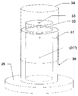
Fig. 2 shows the mounting of a functional sleeve outside the printing machine,
and
Fig. 3 shows the cross section of an intermediate sleeve with a detachable
joint.
DETAILED DESCRIPTION OF THE PRESENTLY PREFERRED EMBODIMENTS
In variable-circumference web-fed offset printing machines according to the
invention, core cylinders are provided on a machine base instead of the
conventional
fixed-format plate and blanket cylinders, on which core cylinders various
intermediate
sleeves with different wall thicknesses can be mounted, so that variable-
format surfaces
are produced. These intermediate sleeves can bear both printing plates and
rubber
blankets.
The more extensive equipment of such a machine base with further printing
equipment which can be adapted to the various circumferential lengths, such as
inking
units, damping units or, if appropriate, also in-press image-setting
equipment, web
guiding systems or folding equipment, will not be discussed further.
Fig. 1 illustrates a cross section of an intermediate sleeve (3) mounted on a
core cylinder (1). The core cylinder (1) is designed as a conventional air
cylinder with
compressed-air channels (2) distributed over the circumference, which permit
the
intermediate sleeves (3) to be pushed on axially and shrunk on radially in a
reversible
manner. The diameter of the core cylinder (1) is defined by the smallest
sectional length
within the range of formats to be covered and the layer thickness of the
functional
surface fitted. In order to cover a wide format range, it may be necessary to
provide
various core cylinders (1) with increasing diameters.
5
---- _.~?--- ~
CA 02347972 2001-05-17
The intermediate sleeve (3) is constructed on a carrier layer (5) which
preferably consists of glass-fibre reinforced plastic and, with its
cylindrical inner face,
forms a detachable joint with the core cylinder (1), its diameter being
dimensioned such
that a press fit is produced. The carrier layer (5) is a thin layer with a
thickness of, for
example, about 1 millimeter.
The carrier layer (5) is followed by a compressible intermediate layer (6) of
preferably about 3 millimeters layer thickness, which allows the carrier layer
(5) a
reversible expansion and permits the intermediate sleevE: (3) to be shrunk
onto the core
cylinder (1). The intermediate layer (6) consists of porous polyurethane, for
example.
Other compressible materials can also be employed.
The intermediate layer (6) is closed off by a thin transition layer (7) - for
example about 1 millimeter thick - preferably made of glass-fibre reinforced
plastic, onto
which a bridging layer (8) with a variable wall thickness is fitted.
The bridging layer (8) is preferably produced from porous rigid polyurethane
foam, and its layer thickness is selected in accordance with the sectional
length of the
format for which the respective intermediate sleeve (3) is provided. Because
of the
continuously variable thickness of the bridging layer (8), in principle any
desired format
length can be implemented. The maximum thickness of the bridging layer (8) is
about
35 millimeters. If reinforcing structures are used, however, thicker layers
are also
possible. As a result of the preferred material selection in accordance with a
low
density, the intermediate sleeves (3) have a low weight and may be handled
very easily
by hand and permit ergonomic replacement within the printing machine. In
addition,
because of a low thermal conductivity and low heat capacity, the intermediate
sleeves
are also suitable for printing processes in which printing plates are
thermally loaded in
the printing unit, such as in the case of printing-plate production within the
printing
machine (thermal transfer processes, computer-to-press ltechnologies).
The bridging layer (8) is surrounded by a thin covering layer (9), preferably
made of glass-fibre reinforced plastic. The thickness of -the covering layer
(9) is about
1 millimeter, for example, and its cylindrical circumferential surface is used
as a joint
with the functional sleeve (4).
6
CA 02347972 2001-05-17
For the covering layer (9) and the carrying layer (5) which, at their outer
and
inner surface, respectively, have detachable joints so that functional sleeves
(4) can be
shrunk on reversibly or, respectively, so that they can be mounted or
dismantled from
the core cylinder (1), wear-resistant materials, such as glass-fibre
reinforced plastics,
must be provided.
Close to one end of the intermediate sleeve (3), on the circumference,
compressed-air channels (10) are provided, which lead from the hollow inner
side,
through all the layers, to the outer surface. They are lpreferably distributed
uniformly
around the circumference and oriented radially in relation to the axis of
rotation. In order
to improve the air pad during the fitting of the functional sleeve (4),
further channels
running radially (31', Fig. 2) could be provided, being arranged in an axially
offset
manner approximately centrally between the end faces of the intermediate
sleeve (3).
As a result of the particularly advantageous arrangement of the compressed-air
channels (10) in the radial direction, it is possible to dispense with
longitudinal channels
- running parallel to the cylinder axis - so that the intermediate sleeves (3)
can be
produced very simply, and no minimum thickness for the bridging layer (8) has
to be
taken into account.
The functional sleeve (4) which can be mounted detachably on the covering
layer (9) may be a metal or plastic sleeve, which is used as a printing
surface or as a
carrier for a rubber blanket and, if required, can be replaced simply and cost-
effectively.
Fig. 2 shows the operation of changing a functional sleeve (34) outside the
printing machine. For this purpose, one end face of the intermediate sleeve
(30) is
closed by being set up on a support (35), and the other end, in the vicinity
of which the
compressed-air channels (31) running radially are arranged, is sealed off with
a cover
(32). Via a compressed-air connection (33) on the cover (32), the cavity in
the
intermediate sleeve (30) is supplied with compressed air, which escapes
through the
compressed-air channels (31) and possibly through additional - centrally
arranged -
compressed-air channels (31') on the outer surface of the intermediate sleeve
(30). The
cover (32) is dimensioned such that the functional sleeve (34) can be put over
it onto
the intermediate sleeve (30) and can be pushed on the air pad which forms.
After the
7
-----
-R--
CA 02347972 2001-05-17
sleeve has been positioned, the compressed air is swi-tched off and the cover
(32) is
removed. The functional sleeve (34) produces a shrink fit on the intermediate
sleeve
(30) and closes the compressed-air channels (31, possibly also 31') on the
outside. The
intermediate sleeve (30) therefore prepared as a plate or rubber-covered
cylinder can
then be fitted to the corresponding core cylinder (desi(ined as an air
cylinder) in the
printing machine and, at any time, replaced for a different intermediate
sleeve (30)
having a different format for the production of a different section length.
As a result of this particularly advantageous method, it is possible to manage
with conventional air cylinders on the printing machine, and it is not
necessary for any
additional air connections or changeover valves to be provided, which reduces
the
investment costs.
With a known applicator structure, a printing company can tailor the
necessary number of intermediate sleeves (30) in advaince with appropriate
format as
plate and rubber-covered cylinders, and change over the machine base in an
extremely
short time.
Fig. 3 shows a further exemplary embodiment in which the functional layer
(21) is non-detachably joined to an intermediate sleeve (20). This
intermediate sleeve
(20) likewise comprises a carrier layer (5'), intermediate layer (6') and
transition layer
(7'), which are followed by the variable-thickness bridgirig layer (8') and
the functional
layer (21) being joined directly to the bridging layer (8') without any
covering layer (9,
Fig. 1). Such intermediate sleeves (20) have only a single detachable joint,
namely that
between the carrier layer (5') and core cylinder (1), and can therefore be
designed
particularly advantageously without any air channels, which makes their
production
simpler and more beneficial.
A rubber blanket can, for example, be adhesively bonded onto the bridging
layer (8'), sprayed on or vulcanized on. By means of chemical or electroplated
metallization of the circumferential surface of the bridging layer (8'), an
intermediate
sleeve (20) can be tailored as a printing plate.
A further production option provides for a printing plate or a rubber blanket
to
be inserted into a cylindrical mould and, concentrically with this, a
composite of carrier
8
CA 02347972 2001-05-17
layer (5'), intermediate layer (6') and transition layer (7'') to be arranged
in its interior.
The intermediate space between transition layer (7') and the printing plate or
the rubber
blanket is then filled with plastic foam. After the plastic has cured, the
finished
intermediate sleeve (20) tailored as a printing or rubber-covered cylinder can
be
removed from the apparatus. Dispensing with the second detachable joint means
that
more accurate production tolerances can be achieved and, because of the
integration of
the functional surface into the production process of the variable-format
intermediate
sleeve (20), the costs can be reduced.
In the case of this integrated production process, it is also possible,
instead of
the functional surface, to fix a conventional clamping channel for
conventional printing
plates or rubber blankets in the mould and to join them to the intermediate
layer (7') by
foam filling. For this purpose, the clamping channel can be arranged in a
housing, which
is fixed in the bridging layer (8') by anchoring parts surrounded by foam.
One advantageous embodiment of the invention illustrated in Figs 1-3 is the
application to a rubber-covered cylinder of an offset printing machine.
List of reference symbols
1 Core cylinder
2 Compressed -air channel
3 Intermediate sleeve
4 Functional sleeve
5,5' Carrier layer
6,6' Intermediate layer
7,7' Transition layer
8,8' Bridging layer
9 Covering layer
10 Compressed-air channel
20 Intermediate sleeve
21 Functional layer
30 Intermediate sleeve
9
_ _ _ ------ __ - --- --- ~
CA 02347972 2001-05-17
31,31' Compressed-air channel
32 Cover
33 Compressed-air connection
34 Functional sleeve
35 Support
Thus, while there have shown and described and pointed out fundamental
novel features of the invention as applied to a preferrecl embodiment thereof,
it will be
understood that various omissions and substitutions and changes in the form
and
details of the devices illustrated, and in their operation, may be made by
those skilled in
the art without departing from the spirit of the invention. For example, it is
expressly
intended that all combinations of those elements and/or method steps which
perform
substantially the same function in substantially the same way to achieve the
same
results are within the scope of the invention. Moreover, it should be
recognized that
structures and/or elements and/or method steps shown and/or described in
connection
with any disclosed form or embodiment of the invention may be incorporated in
any
other disclosed or described or suggested form or embodiment as a general
matter of
design choice. It is the intention, therefore, to be limited only as indicated
by the scope
of the claims appended hereto.
7T_ ----
---