Note: Descriptions are shown in the official language in which they were submitted.
CA 02348041 2001-07-25
HANGING FILE SYSTEM
BACKGROUND OF THE INVENTION
1. Field of the Invention
This invention relates to paper filing systems, and more particularly to
hanging file
systems.
2. Description of Related Art
In the past, hanging folders were designed to help maintain papers neatly in
file drawers.
A hanging folder has hangers that extend from each end of the opening of the
folder, which ride
on rails provided across a file drawer. When papers are placed in the hanging
folder, they are
either first organized in a separate file folder or simply left loose in a
stack. Chinese Utility
Model Patent No. 982124627 (filed April 2, 1998; issued May 24, 1999; assigned
to Idea
Enhancement Group Inc., the assignee of the present application), disclosed a
new hanging
binder that organizes, binds and files the papers in a hanging file drawer,
without requiring the
use of a separate hanging folder and file folder. (This Chinese patent is
fully incorporated by
reference herein) The hanging binder disclosed has four posts spaced apart
along a binding spine
and a binder flap having four holes spaced apart to match the posts. The
papers to be filed have
holes punched along an edge at spacing matching the location of the posts. To
file a paper, the
paper is placed against the binder with the posts through the holes, and the
binder flap is closed
onto the posts with the tip of the posts into the holes on the binder cover.
The tips of the posts
are snapped into the holes on the binder flap, thus securing the paper on the
posts. To remove a
1
CA 02348041 2001-07-25
paper, the binder flap is unsnapped to provide access to the paper. The
hanging binder has a
hanger extending from each end of its spine, which hangers may retract into
the spine when the
hanging binder is not placed in a hanging file drawer. Each hanger is
separately supported in a
cantilevered fashion by the two posts closest to the respective end.
The above-mentioned hanging binder maintains a stack of loose-leaf papers in
an
organized fashion for the convenience of future references. It also maintains
the stack of loose-
leaf papers in a manner that allows a person the flexibility and ease of
inserting papers to or
removing papers from the stack. Further, it maintains the stack of loose-leaf
papers in a manner
that allows easy turning of the pages to allow a person to review the papers.
The present invention provides an improvement over the earlier hanging binder
design.
2
CA 02348041 2001-07-25
SUMMARY OF THE INVENTION
The present invention is directed to a hanging file system that makes use of
an improved
hanging binder. The filing system includes a number of complementary hanging
file supports,
implementations and accessories.
In one aspect of the present invention, the improved hanging binder has two
telescopic
retractable hanger members, which are supported by posts to extend at each end
of the spine of
the binder in a cantilevered manner. A common center post supports a
telescopic section of the
hanger members. This reduces the number of posts, thus simplifies the design
and construction
of the hanging binder, and improves ease of use.
In another aspect of the present invention, hanging binder supports are
designed to
complement usage of the hanging binder to provide filing of loose-leaf papers.
In accordance
with one embodiment of the present invention, a hanging file sleeve or box
provides support for
portable storage of hanging file. In accordance with another embodiment of the
present
invention, a hanging file carrying case provides easy handling of hanging
files. In accordance
with a further embodiment of the present invention, a foldable hanging file
base provides support
of hanging files. The foldable hanging file base has a frame structure that
comprises slender
members. Soft or flexible panels may be supported on the frame structure to
provide protection
of the contents from the environment. The frame structure may be folded or
collapsed when the
base is not in use.
In another aspect of the present invention, a hanging binder supports a
receptacle that
provides filing of loose papers and/or articles. In accordance with one
embodiment of the
present invention, the receptacle is in the form of a file pocket or envelope,
with holes punched
along an edge for hanging on the posts on the hanging binder.
3
CA 02348041 2001-07-25
In another aspect of the present invention, a hanging binder supports at least
one loose
cover with enough stiffness to protect the contents within the hanging binder.
In accordance
with one embodiment of the present invention, a front cover and a back cover
have holes
punched along an edge for hanging on the posts on the hanging binder.
In another aspect of the present invention, a hanging binder has a fixed outer
jacket that
protects the contents within the hanging binder, as well as the hanging binder
itself. In
accordance with one embodiment of the present invention, the jacket structure
surrounds the
spine of the hanging binder and extends to cover the contents within the
hanging binder. The
jacket structure is attached to the spine by various means.
4
CA 02348041 2001-07-25
BRIEF DESCRIPTIONS OF THE DRAWINGS
For a fuller understanding of the nature and advantages of the present
invention, as well
as the preferred mode of use, reference should be made to the following
detailed description read
in conjunction with the accompanying drawings. In the following drawings, like
reference
numerals designate like or similar parts throughout the drawings.
Fig. 1 is a perspective view of a hanging binder in accordance with one
embodiment of
the present invention, with the hangers retracted.
Fig. 2 is a perspective view of the hanging binder broken away to show
internal parts,
with the hangers fully extended.
Fig. 3A is a perspective view of the spine of the binder; Fig. 3B is a
perspective view of
the hanger members in the extended state.
Fig. 4A is a front view of the hanger members separated; Fig. 4B is a front
view of the
hanger members in the extended state; Fig. ~C is a front view of the hanger
members in the
retracted state.
Fig. SA is a sectional view of the hanger member taken along line SA-SA in
Fig. Fig. 3B;
Fig. SB is a sectional view of the binder taken along line SB-SB in Fig. 2.
Fig. 6 is a top view of the post head region on the spine.
Fig. 7 is a sectional view of the post taken along line 7-7 in Fig. 6.
Fig. 8 is a perspective view of a hanging file box in accordance with one
embodiment of
the present invention.
Fig. 9 is a perspective view of a hanging file carrying case in accordance
with one
embodiment of the present invention.
5
CA 02348041 2001-07-25
Fig. 10 is a perspective view of a foldable hanging file base in accordance
with one
embodiment of the present invention.
Fig. 11 is a perspective view of a hanging file pocket in accordance with one
embodiment
of the present invention.
Fig. 12 is a perspective view of hanging file cover sheets in accordance with
one
embodiment of the present invention.
Fig. 13 is a perspective view of a hanging file jacket in accordance with one
embodiment
of the present invention.
Fig. 14 is a sectional view of the binder with the hanging file jacket taken
along line 14-
14 in Fig. 13.
6
CA 02348041 2001-07-25
DESCRIPTION OF PREFERRED EMBODIMENTS
The present description is of the best presently contemplated mode of carrying
out the
invention. This description is made for the purpose of illustrating the
general principles of the
invention and should not be taken in a limiting sense. The scope of the
invention is best
determined by reference to the appended claims.
Reference is made to Chinese Utility Model Patent No. 982124627 (filed April
2, 1998;
issued May 24, 1999; assigned to Idea Enhancement Group Inc., the assignee of
the present
application), which is fully incorporated by reference herein.
The present invention is directed to a hanging file system that makes use of
an improved
hanging binder. The filing system includes a number of complementary hanging
file supports,
implementations and accessories.
In one aspect of the present invention, an improved hanging binder reduces the
number of
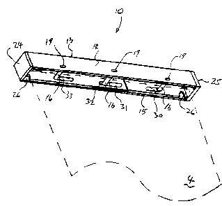
posts required to support retractable hangers. Figs. 1 to S illustrate the
improved hanging binder
in accordance with one embodiment of the present invention. The hanging binder
10 comprises
an elongated spine 12 and two hanger members 20 and 22 slidable within the
spine 12. The
spine 12 has a generally U-shaped cross-section (i.e., generally a U-shaped
channel; see Fig.
3A). It has a back 13 and two opposing flaps 14 and 15. The flap 15 has three
posts 16
extending perpendicularly from the flap 15, across the inside of the spine 12,
to the flap 14. The
flap 14 is hingedly connected to the back 13 and has three holes 18 matching
the location of the
tips 19 of the posts. Referring also to Figs. 6 and 7, the holes 18 have a
constriction 21, and the
posts 16 have a ball-head tip 19 and a neck 17. The ball-head tip 19, neck 17,
hole 18 and
constriction 21 are sized to cooperate as a snap fastener, such that the posts
16 and the holes 18
snap together when the posts 16 are inserted through the holes 18. The posts
16 and holes 18
7
CA 02348041 2001-07-25
may have a cylindrical, oval, square or rectangular cross-sections. The
illustrated embodiment
shows an elongated oval cross-section. Alternatively, other types of
releasable interlocking
structure may be used for coupling the flap 14 and posts 16.
The spine 12 may be made of a plastic or light metal material. For example,
plastic such
as polyethylene and polyvinyl chloride may be used to make the spine. The
flaps 14 and 15 and
the back 13 may be formed from an initially flat piece of material. The flaps
14 and 15 may be
bent from the back 13 and~shaped to form the U-shaped (cross-section) spine
12. To facilitate
bending, the sheet material may be scored at the bends 1 and 2 (Fig. 3A) or
the thickness of the
material is otherwise reduced at the bends. The bend 2 acts as a hinge for the
flap 14. The posts
16 may be formed integral to the flap 15 or separately and welded to the flap
15. Alternatively,
the flaps 14 and 15 may b separate pieces connected to the back 13.
Referring to Figs. 3B to 5, the hanger members 20 and 22 have a generally L-
shaped
cross-section, except at the ends 24 and 25. The ends 24 and 25 are generally
U-shaped in cross-
section, and have generally U-shaped notches 26 on the sides, which define
hangers 27 for riding
on hanging file support rails typically provided in file drawers and the like.
The hanger members
may be made out of the same materials that can be used to make the spine. At
the other ends 28
and 29 of the hanger members 20 and 22, the hanger members can slide relative
to one another in
a telescopic manner. The end 28 is reduced in overall size to fit inside of
the end 29. Figs. 2, 3,
and 4B show the hanger members in an extended state;,Figs 1 and 4C show the
hanger members
in a fully retracted state.
On each hanger member, there are two elongated slots (30, 31, 32, 33). The
slots 30-33
are positioned such that the posts 16 extend through the slots 30-33 in the
assembled binder. In
the assembled state, the slots 31 and 32 overlap at the center post 16. The
slots 30-33 are so
8
CA 02348041 2001-07-25
sized and positioned such that in the fully extended position of the hanger
members 20 and 22,
the posts 16 stops at the inside ends 34-37 of the slots 30-33; and in the
fully retracted position,
the posts 16 stops at the outside ends 38-41 of the slots 30-33. The slots 30
and 33 have
generally V-shaped or half-round protrusions 44 along the longitudinal edges
of the slots 30 and
33. The protrusions 44 are positioned from the ends 34, 37, 38 and 41 of the
slots 30 and 33
such that the posts 16 are trapped by the protrusions 44 when the posts are
against the ends 34,
37, 38 and 41 of the slots 30 and 33. When the hanger members are in the fully
retracted state as
shown in Fig. 4B, the posts 16 are trapped against ends 38 and 41 of slots 30
and 33. In the fully
extended state as shown in Fig. 4C, the posts 16 are trapped against ends 34
and 37 of slots 30
and 33. The posts 16 can slide over the protrusions 44 upon applying a force
to extend or retract
the hanger members 30 and 33. To facilitate sliding over the protrusions 44,
slots 46 are
provided in parallel to the edge of the slots 30 and 33 on which the
protrusions 44 are located,
next to narrow adjoining strips 48. When a force is applied to slide the
hanger members 30 and
33 relative to each other, the posts 16 press against the protrusions 44, and
in a cam action, push
the protrusion "aside" while the narrow adjoining strips 48 flex to give way
laterally because of
the slots 46.
The hanger members 30 and 33 are essentially supported in a cantilevered
manner by the
posts 16. Two posts 16 are needed to support each hanger member. By using a
common center
post 16 to support the inside end of each hanger member, the number of posts
is reduced, thus
simplifying the design and construction of the hanging binder 10.
The size of the hanging binder 10 may correspond to any standard size paper,
such as A4
size, legal size, letter size, etc. The position and spacing of the posts 16
may correspond to the
spacing of holes made by standard hole-punchers.
9
CA 02348041 2001-07-25
To file a paper in the hanging binder 10, the flap 13 is opened at its hinge
at bend 2, away
from the posts 16. The paper is placed against the back 13 with the posts 16
through holes
punched along one edge of the paper. The flap 14 is closed onto the posts 16
with the tip 19 of
the posts into the holes on the binder cover. The tips 19 of the posts 16 are
snapped into the
holes 18 on the flap 14, thus securing the paper on the posts 16. To remove a
paper, the flap 14
is unsnapped from the posts 16 to provide access to the paper. Fig. 1 shows
the hanging binder
with papers 4 filed thereon. The hanger members may be retracted into the
spine 12 to conceal
the hanger 27 when the hanging binder 10 is not placed in a hanging file
drawer. This provides a
clean elegant binder that can be handled without the hangers 27 getting in the
way. When the
binder 10 is placed in a file drawer, the hanger members 20 and 22 are
extended to expose the
hangers 27. The binder is supported with the hangers 27 riding on rails
typically provided in a
file drawer, in which the papers filed thereon will hang vertically.
Unlike the four-pin structure, which requires snapping and unsnapping of four
posts to
place and remove papers from the binder, less posts used in the present
invention results in a
structure that requires less effort for a person to use the binder 10.
In another aspect of the present invention, hanging binder supports are
designed to
complement usage of the hanging binder to provide filing of loose-leaf papers.
As shown in Fig.
8, in accordance with one embodiment of the present invention, a hanging file
sleeve or box 50
provides support for portable storage of hanging file. The box 50 has a
rectangular sleeve 52
having an opening 54. Inside the opening, at two opposing ends are support
rails 56. In the
embodiment shown, the opening is a narrow rectangular shape, and the support
rails are slots
oriented with their edges facing towards the opening. The size of the sleeve
52 and the spacing
between the rails 56 are such to match the hanger 27 when they are fully
extended from the spine
CA 02348041 2001-07-25
12. The hanging binder 10 can be inserted in the sleeve 52 and supported on
the rails at the
hangers 27. The distance between the rails 56 and the edge of the opening 54
may be such that
the back 13 of the binder 10 would be flush with the edge of the opening 54
when the binder 10
is supported on the rails 56. This results in an elegant profile. To
facilitate removal of binders
10 from the sleeve 52, the panels at the sides of the opening 54 are provided
with cutouts 58.
It is noted that while the box 50 is designed for supporting hanging binders
10
horizontally (i.e., the opening 54 horizontal), the box 50 may be stored on a
shelf with the
opening 54 vertical. It is expected that one would typically insert and remove
binders 10 with
the opening horizontal. The width of the sleeve 52 may be any size desired to
hold a desired
number of hanging binder 10. The hanging binders 10 may be color coded in
accordance with
subject matter.
Referring to Fig. 9, in accordance with another embodiment of the present
invention, a
hanging tile carrying case 60 provides easy transport and handling of hanging
files. The case 60
is essentially similar in structure as the box 50 in the previous embodiment,
with the exception
that a carrying handle 62 is provided on an additional panel 64 that closes
the opening 66. There
is also a panel 68 that has a clasp, latch or other types of fastener 69 that
secures the panel 68 in a
closed position. There are rails 67 and cutouts 65 as in the previous
embodiment. Optional flaps
63 may be provided at opposing ends of the opening 66. This may be folded and
tucked under
the panel 64 to protect the hanging binders 10 carried in the case 60.
The case 60 and the sleeve 52 may be made of a rigid material, such as plastic
or metal.
Referring to Fig. 10, in accordance with a further embodiment of the present
invention, a
foldable hanging file base 70 facilitates storage of the case during shipping
and saves space when
not in use. The base 70 comprises a frame structure of slender members 72. The
members 72
11
CA 02348041 2001-07-25
may be made from solid rods or hollow tubes of light metal or plastic. Two
horizontal members
74 provide the support rails for hanging binders 10 shown in dotted lines in
Fig. 10. Soft or
flexible panels 71 may be supported or draped between the members 72 to form
an enclosure to
provide protection of the contents from the environment. The frame structure
may be folded or
collapsed at hinge 76 to a generally flat profile when the case 60 is not in
use.
In another aspect of the present invention, a hanging binder supports a
receptacle that
provides filing of loose papers and/or articles. Referring to Fig. 11, in
accordance with one
embodiment of the present invention, the receptacle is in the form of an
envelope or a file pocket
80, which has holes 82 punched along flange 83 for hanging on the posts 16 on
the hanging
binder 10. The file pocket 80 may have a flap 84 that closes an opening in the
file pocket 80 for
insertion of papers or articles by means of a Velcro fastener 88 or other
types of releasable
fastener or clasp. The file pocket 80 may be made of clear, colored and/or
translucent plastic. A
Label holder 86 may be provided on the front of the file pocket 80 for holding
a content
identification label.
In another aspect of the present invention, a hanging binder supports at least
one loose
cover with enough stiffness to protect the contents within the hanging binder
during handling and
storage. Referring to Fig. 12, in accordance with one embodiment of the
present invention, the
cover structure 90 consists of a front cover 98 and a back cover 99, both of
which have holes 92
punched along flanges 93 for hanging on the posts 16 on the hanging binder 10.
Since the holes
92 hang on the posts 16, the cover structure 90 can be removed from the binder
10 or
reconfigured in any manner desired by the user. A label holder 96 may be
provided on the front
cover 98 for holding a content identification label. The front and back covers
98 and 99 are
12
CA 02348041 2001-07-25
generally flat, preferably made of a plastic material. The material chosen
should be stiff or the
thickness of the material should be chosen so that the covers are of a
stiffness that adequately
protects the contents during handling and storage.
In another aspect of the present invention, a hanging binder has a fixed outer
jacket that
protects the contents within the hanging binder, as well as the hanging binder
itself, during -_
handling and storage. Referring to Figs. 13 and 14, in accordance with one
embodiment of the
present invention, the jacket structure 100 comprises jacket front 102, jacket
back 104, and
jacket side 106 that surround flap 14, flap 15, and back 13> respectively, of
the spine 12. The
jacket front 102, back 104, and side 106 may be integrally formed from a
single piece of material
by bending along corners 112 and 114. Alternatively, the jacket structure 100
may be separately
formed and then joined. The jacket structure 100 is attached to the spine 12
and extends to cover
the contents within the hanging binder 10. In the illustrated embodiment,
rivets 110 attach the
jacket structure 100 to the spine 12. The jacket structure 100 may be attached
to the spine 12 by
other means, such as by using other fasteners besides rivets, by applying an
adhesive, by plastic
welding, or even by forming the jacket structure and the spine as an integral
structure. In
accordance with another embodiment of the present invention, the jacket
structure 100 has one or
more clear pockets 120 on the jacket front 102, jacket back 104, or jacket
side 106 so that the
pocket 120 can display papers, which slide in an opening 122. The pocket 120
is attached to the
jacket structure 100 by any adhesive, joining, or forming means.
While the invention has been described in detail with respect to the
illustrated
embodiments in accordance therewith, it will be apparent to those skilled in
the art that various
changes, modifications, substitutions, alterations and improvement may be made
without
departing from the scope and spirit of the invention as defined by the
appended claims.
13