Note: Descriptions are shown in the official language in which they were submitted.
CA 02348588 2004-05-26
1
SPECIFICATION
PORTABLE COMMUNICATIONS DEVICE WITH COMPACT BATTERY
COMPARTMENT
FIELD OF THE INVENTION
The present invention relates to portable wireless
communications devices, such as portable telephones and
pagers, which comprise as housed in a flat casing a
circuit board for wireless communication and a cell for
supplying power to the circuit board.
BACKGROUND OF THE INVENTION
FIG_ 7 shows the construction of a conventional
portable telephone in section orthogonal to the
longitudinal direction thereof. A circuit board (7) is
installed inside a flat casing (9) comprising a front
case (91) and a rear case (92) which are made of a
synthetic resin. A peripheral wall (95) and a bottom
wall (96) which are molded integrally with the rear case
(92) form a cell chamber for housing a cell (2) therein.
A lid (93) for closing the cell chamber is removably
attached to the rear case (92).
With portable telephones which need to be compacted
and reduced in thickness, the electronic parts to be
CA 02348588 2001-04-25
2
mounted on the circuit board and the cell have been made
compact almost to the greatest possible extent, and
extreme difficulties are encountered in making portable
telephones more compact and thinner by compacting the
components.
For example, even if it is attempted to reduce the
thickness of the telephone shown in FIG. 7, the circuit
board (7) having a large number of electronic parts
mounted thereon and the cell (2) have been reduced in
thickness to the limit as stated above, while the lid
(93) and the casing (9) are also limited to about 0.7 mm
in thickness in view of the problems as to the strength.
The bottom wall (96) of the cell chamber is indispensable
for supporting the cell (2) in the chamber and blocking
water ingressing into the cell chamber to protect the
circuit board (7) from the water.
The front case (91) and the rear case (92) providing
the casing (9) are molded from resin with use of a pair
of molds, respectively. These cases need to be designed
in shape with consideration given to the draft of each
mold. With the rear case (92), for example, a parting
line A-A for the pair of molds is located at the position
of the boundary between the cell chamber peripheral wall
CA 02348588 2001-04-25
3
(95) and the cell chamber bottom wall (96), and the
peripheral wall (95) needs to be so shaped in section as
to incline at a specified angle 6 (e. g., 3 deg) as shown
in FIG. (12) (b).
Assuming that the peripheral wall (95) has a height
H, for example, of 10 mm, the inclination of the wall
(95) therefore gives an excess of 0.52 mm to the lateral
width thereof, with the result that the distance B1' from
the side face of the cell (2) to the outer peripheral
surface of the rear case {92) increases by the excess of
0.52 mm, thus entailing the problem of increasing the
overall width of the casing (9).
An object of the present invention is to provide a
novel construction for portable telephones or like
portable wireless communications devices which serves to
make the device more compacted and thinner than
conventionally.
DISCLOSURE OF THE INVENTION
The present invention provides a first portable
wireless communications device which comprises a casing
(1) formed with a peripheral wall (5) defining a cell
chamber and having an opening at each of an inlet side of
the cell chamber and a bottom side thereof, the opening
CA 02348588 2001-04-25
4
at the inlet side of the cell chamber being provided with
a lid (13) removably attached to the casing (1) for
closing the opening, the opening at the bottom side of
the cell chamber being fixedly provided with a sheet for
closing the opening.
The sheet is in the form of a flat plate or tray.
The flat platelike sheet (33) has a contour extending
outwardly of the opening of the peripheral wall (5) at
the cell chamber bottom side. The traylike sheet (3) has
a bottom wall (31) clc~sing the opening of the peripheral
wall (5) at the cell chamber bottom side, and a side wall
(32) extending from an outer periphery of the bottom wall
(31) and in intimate contact with the peripheral wall (5).
The sheet included in the telephone of the invention
described is made of PET or like synthetic resin or metal,
and can be thinner than the conventional cell chamber
bottom wall of synthetic resin which is molded integrally
with the casing. Accordingly, the communications device
of the invention can be reduced in thickness by an amount
corresponding to the difference in thickness between the
sheet and the conventional cell chamber bottom wall.
Stated specifically, the sheet has a rear surface in
contact with a surface of a circuit board (7). An
CA 02348588 2001-04-25
external force acting on the cell in the cell chamber is
then received by the surface of the circuit board (7)
through the sheet.
The casing (1) is molded from a resin with use of a
5 pair of molds, and the peripheral wall (5) is molded from
the resin with a parting line of the pair of molds
positioned at an intermediate portion of thickness of the
casing. The casing thus constructed can be smaller in
lateral width than in a portable communications device
which comprises a cell chamber peripheral wall (5) having
the same height as that of the invention, and a casing
molded from a resin, with the same draft [angle A in FIG.
12 (a)] as in the invention given and with a parting line
of a pair of molds positioned at one of the ends of the
casing in the direction of its thickness.
Further stated specifically, the peripheral wall (5)
comprises a first peripheral wall portion (51) at the
cell chamber inlet side and a second peripheral wall
portion (52) at the cell chamber bottom side, with the
parting line serving as a boundary between the wall
portions (51), (52), t:he peripheral wall portions (51),
(52) defining respective spaces enlarged in a direction
away from the parting line, the first peripheral wall
CA 02348588 2001-04-25
6
portion (51) projecting at the position of the parting
line toward a center of the cell chamber beyond the
second peripheral wall portion (52) to form a stepped
portion (53) between the peripheral wall portions (51),
(52). With this specific construction, the cell can be
loaded into the cell chamber with ease since the first
peripheral wall portion (51) at the cell chamber inlet
side provides a guide face for loading.
With the stepped portion (53) formed positively
between the first and second peripheral wall portions
(51), (52), the first peripheral wall portion (51) can be
caused to project beyond the second peripheral wall
portion (52) at all times at the position of the parting
line despite molding errors, whereby the cell can be
guided smoothly.
Further stated specifically, an outer end of the
side wall (32) of the traylike sheet (3) is in engagement
with the stepped portion (53) of the peripheral wall (5).
This effectively obviates the likelihood that the water
drops ingressing into the cell chamber will pass between
the side wall (32) of the traylike sheet (3) and the
chamber wall (5) to wet the circuit board (7).
The side wall (32) of the traylike sheet (3) is
CA 02348588 2001-04-25
7
affixed to a surface of the second peripheral wall
portion (52) of the peripheral wall (5). An external
force acting on the cell in the cell chamber is then
received by the trayli.ke sheet (3). Moreover, the water
drops ingressing into the cell chamber can then be more
effectively prevented from passing between the side wall
(32) of the traylike sheet (3) and the chamber wall (5)
to wet the circuit board (7).
The present invention provides a second portable
communications device which comprises a casing (1) molded
from a resin with use of a pair of molds and formed with
a peripheral wall (5) defining the cell chamber, the
peripheral wall (5) being molded from the resin with a
parting line of the pair of molds positioned at an
intermediate portion of thickness of the casing, the
peripheral wall (5) having an opening at each of an inlet
side of the cell chamber and a bottom side thereof, the
opening at the inlet ~;ide of the cell chamber being
removably provided with a lid (13) for closing the
opening.
The casing thus constructed can be smaller in
lateral width than in a portable communications device
which comprises a cell. chamber peripheral wall (5) having
CA 02348588 2001-04-25
8
the same height as that of the invention, and a casing
molded from a resin, with the same draft [angle A in FIG.
12 (a)] as in the invention given and with a parting line
of a pair of molds positioned at one of the ends of the
casing in the direction of its thickness.
Stated specifically, the opening of the peripheral
wall (5) at the bottom side of the cell chamber is
fixedly provided with a sheet for closing the opening.
The sheet is in the form of a flat plate or tray.
The flat platelike sheet (33) has a contour extending
outwardly of the opening of the peripheral wall (5) at
the cell chamber bottom side, the outward extension being
in intimate contact with an end face of the peripheral
wall (5). The traylike sheet (3) has a bottom wall (31)
closing the opening of the peripheral wall (5) at the
cell chamber bottom side, and a side wall (32) extending
from an outer periphery of the bottom wall (31) and in
intimate contact with the peripheral wall (5).
The sheet included in the specific construction
described is made of F?ET or like synthetic resin or metal,
and can be thinner than the conventional cell chamber
bottom wall of synthetic resin which is molded integrally
with the casing. Accordingly, the communications device
CA 02348588 2001-04-25
9
of the invention can be reduced in thickness by an amount
corresponding to the difference in thickness between the
sheet and the conventional cell chamber bottom wall.
Further stated specifically, the peripheral wall (5)
comprises a first peripheral wall portion (51) at the
cell chamber inlet side and a second peripheral wall
portion (52) at the cell chamber bottom side, with the
parting line serving as a boundary between the wall
portions (51), (52), the peripheral wall portions (51),
(52) defining respective spaces enlarged in a direction
away from the parting line, the first peripheral wall
portion (51) projecting at the position of the parting
line toward a center c>f the cell chamber beyond the
second peripheral wall portion (52) to form a stepped
portion (53) between the peripheral wall portions (51),
(52). With this specific construction, the cell can be
loaded into the cell chamber with ease since the first
peripheral wall portion (51) at the cell chamber inlet
side provides a guide face for loading.
With the stepped portion (53) formed positively
between the first and second peripheral wall portions
(51), (52), the first peripheral wall portion (51) can be
caused to project beyond the second peripheral wall
CA 02348588 2004-05-26
portion (52) at all times at the position of the parting
line despite molding errors, whereby the cell can be
guided smoothly.
Further stated specifically, an outer end of the side
5 wall (32) of the traylike sheet (3) is in engagement with
the stepped portion (53) of the peripheral wall (5). This
effectively obviates the likelihood that the water drops
ingressing into the cell chamber will pass between the
side wall (32) of the traylike sheet (3) and the chamber
10 wall (5) to wet the circuit board (7).
As described above, the first portable communications
device of the invention can be made thinner than in the
prior art, and the second portable communications device
of the invention can be made smaller in lateral width than
conventionally.
In a further aspect, the present invention resides in
a portable wireless communications device wherein a casing
(1) has a circuit board (7) accommodated therein for
wireless communication and a cell chamber formed therein
for accommodating a cell (2) serving as a power source for
the circuit board (7), the communications device being
characterized in that the casing (1) is formed with a
peripheral wall (5) defining the cell chamber, the
peripheral wall (5) having an opening at each of an inlet
CA 02348588 2004-05-26
IOa
side of the cell chamber and a bottom side thereof, the
opening at the inlet side of~the cell chamber being
provided with a lid (13) removably_attached to the casing
(1) for closing the opening, the opening at the. bottom
side of the cell chamber being fixedly provided with a
flat platelike sheet for closing the opening, the flat
platelike sheet having a contour extending outwardly of
the opening of the peripheral wall (5) at the cell chamber
bottom side, the outward extension being in intimate
contact with an end face of the peripheral wall (5).
In another aspect, the present invention resides in a
portable wireless communications device wherein a casing
(1) has a circuit board (7) accommodated therein for
wireless communication and a cell chamber formed therein
for accommodating a cell (2) serving as a power source for
the circuit board (7), the communications device being
characterized in that the casing (1) is formed with a
peripheral wall (5) defining the cell chamber, the
peripheral wall (5) having an opening at each of an inlet
side of the cell chamber and a bottom side thereof, the
opening at the inlet side of the cell chamber being
provided with a lid (13) removably attached to the casing
(1) for closing the opening, the opening at the bottom
side of the cell chamber being fixedly provided with a
CA 02348588 2004-05-26
IOb
flat traylike sheet for closing the opening, the traylike
sheet having a bottom wall (31) closing the opening of the
peripheral wall (5) at the cell chamber bottom side, and a
side wall (32) extending from an outer periphery of the
bottom wall (31) and in intimate contact with the
peripheral wall (5).
In a further aspect, the present invention resides in
a portable wireless communications device wherein a flat
casing (1) has a circuit board (7) accommodated therein
for wireless communication and a cell chamber formed
therein for accommodating a cell (2) serving as a power
source for the circuit board (7), the communications
device being characterized in that the casing (1) is
molded from a resin with use of a pair of molds and formed
IS with a peripheral wall (5) defining the cell chamber, the
peripheral wall (5) being molded from the resin with a
parting line of the pair of molds positioned at an
intermediate portion of thickness of the casing, the
peripheral wall (5) having an opening at each of an inlet
side of the cell chamber and a bottom side thereof, the
opening at the inlet side of the cell chamber being
removably provided with a lid (13) for closing the
opening.
CA 02348588 2004-05-26
lOc
In another aspect, the present invention resides in a
portable wireless communications device including a casing
(1) having a circuit board (7) accommodated therein for
wireless communication and a cell chamber formed therein
for accommodating a cell (2) serving as a power source for
the circuit board (7), wherein the casing (1) is formed
with a peripheral wall (5) defining the cell chamber, the
peripheral wall (5) having an opening at each of an inlet
side of the cell chamber and a bottom side thereof, the
opening at the inlet side of the cell chamber being
provided with a lid (13) removably attached to the casing
(1) for closing the opening, the opening at the bottom
side of the cell chamber being fixedly provided with a
sheet separate from said peripheral wall for closing the
opening.
In a further aspect, the present invention resides in
a portable wireless communications device including a flat
casing (1) having a circuit board (7) accommodated therein
for wireless communication and a cell chamber formed
therein for accommodating a cell (2) serving as a power
source for the circuit board (7), wherein the casing (1)
is molded from a resin with use of a pair of molds and
formed with a peripheral wall (5) defining the cell
chamber, the peripheral wall (5) being molded from the
CA 02348588 2004-05-26
lOd
resin with a parting line of the pair of molds positioned
at an intermediate portion of thickness of the casing, the
peripheral wall (5) having an opening at each of an inlet
side of the cell chamber being removably provided with a
lid (13) for closing the opening, and wherein the opening
of the peripheral wall (5) at the bottom of the cell
chamber is fixedly provided with a sheet separate from
said peripheral wall (5) for closing the opening.
BRIEF DESCRIPTION OF THE DRAWINGS
Fig. 1 is a perspective view of a portable telephone
according to the invention as it is seen from the front
thereof;
FIG. 2 is a perspective view of the telephone as it
is seen from behind;
FIG. 3 is an exploded perspective view of the
telephone which has a flat platelike sheet;
CA 02348588 2001-04-25
11
FIG. 4 is a view in section of the telephone;
FIG. 5 is an exploded perspective view of a portable
telephone having a traylike sheet;
FIG. 6 is a view in section of the telephone;
FIG. 7 is a view in section of a conventional
portable telephone;
FIG. 8 is a fragmentary perspective view of the
portable telephone according to the invention;
FIG. 9 is a sectional view showing the portion F of
FIG. 8 on an enlarged scale;
FIG. 10 is a sectional view showing the portion G of
FIG. 8 on an enlarged scale;
FIG. 11 is a view in section of the telephone along
the longitudinal direction thereof;
1S FIG. 12 (a) and FIG. 12 (b) are diagrams showing a
rear case of the telephone of the invention and that of
the conventional telephone, respectively, in section for
a comparison of the shape and dimensions;
FIG. 13 (a) and FIG. 13 (b) are sectional views for
illustrating the waterproof effect of the portable
telephone of the invention; and
FIG. 14 (a) and FIG. 14 (b) are sectional views
showing a connector restraining structure used in the
CA 02348588 2001-04-25
12
telephone of the invention.
BEST MODE FOR CARRYING OUT THE INVENTION
Portable telephones embodying the present invention
will be described below in detail with reference to the
drawings. Referring to FIG. l, the portable telephone of
the invention has a flat casing (1) comprising the
combination of a front case (11) and a rear case (12)
which are molded from a synthetic resin. The front case
(11) has arranged on its front surface a display (17) and
manual keys (18). As seen in FIG. 2, a lid (13) which is
opened for the replacement of a cell (2) is removably
attached to the rear case (12).
Arranged inside the casing (1) are a circuit board
(7) having a plurality of electronic parts (71) mounted
thereon and a resin chassis (6) as shown in FIG. 3. The
rear case (12) has an opening (14) providing a cell
chamber and defined by a peripheral wall (5), which
comprises a first peripheral wall portion (51) and a
second peripheral wall. portion (52). The border line
between these wall portions is located at an intermediate
portion of the thickness of the casing.
A PET sheet (33) in the form of a flat plate is
affixed to the bottom end face of the cell chamber
CA 02348588 2001-04-25
13
peripheral wall (5) of the rear case (12). The sheet
(33) is generally rectangular, extends outwardly of the
opening (14) of the case (12) and closes the opening (14).
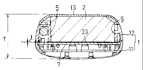
FIG. 4 shows the construction of the telephone in
section orthogonal to the longitudinal direction thereof.
The cell chamber for placing the cell (2) therein is
surrounded by the peripheral wall (5) of the rear case
(12), sheet (33) and lid (13). The sheet (33) has its
outer peripheral portion affixed to the end face of the
case (12) as stated above to realize a waterproof
structure against the ingress of water drops from the
cell chamber. The sheet (33) has a rear surface in
contact with a surface of the circuit board (7). An
external force acting on the cell (2) is received by the
circuit board (7) through the sheet (33).
With the telephone of the invention shown in FIG. 4,
the flat sheet (33) is a member separate from the rear
case (12) and can be given a thickness t which is as
small as, for example, about 0.1 mm. On the other hand,
the cell chamber bottom wall (96) of the conventional
casing (9) shown in FIG. 7 is molded integrally with the
rear case (92) and has a thickness t' which is limited to
about 0.7 mm if smallest. The thickness T of the casing
CA 02348588 2001-04-25
14
(1) of the telephone cf the invention can therefore be
made smaller than the thickness T' of t:he conventional
casing (9) by about 0.6 mm.
Further with the portable telephone of the present
invention, a traylike sheet (3) of PET which is adapted
to place the cell (2) therein can be attached to the cell
chamber peripheral wall (5) in place of the flat sheet
(33) as seen in FIG. 5. The traylike sheet (3) comprises
a bottom wall (31) shaped in the form of a rectangle to
close the bottom opening of the cell chamber of the rear
case (12), and four side walls (32) extending from the
respective four sides of the bottom wall (31). These
four side walls (32) are in intimate contact with the
second peripheral wall portion (52) of the peripheral
wall (5), and at least. one side wall (32) is affixed to
the second wall portion (52). A cushion member (4) is
attached to the inner surface of the sheet side wall (32)
positioned toward the head of the casing.
While the traylike sheet (3) can be shaped in the
form of a box which is open at its upper side as
illustrated, the sheet can be prepared by folding a flat
sheet which corresponds to the box-shaped sheet as
developed to a planar form.
CA 02348588 2001-04-25
The cell (2) is in the form of a flat rectangular
parallelepiped. A cord (74) extending from the
electrode terminals (not shown) of the cell (2) is
provided at its outer end with a male connector (73). On
5 the other hand, a female connector (72) is installed on
the circuit board (7). Electric power is supplied from
the cell (2) to the circuit board (7) by inserting the
male connector (73) into the female connector (72).
FIG. 6 shows the construction of the portable
10 telephone provided with the traylike sheet (3) in section
orthogonal to the longitudinal direction thereof. The
cell chamber for placing the cell (2) therein is
surrounded by the peripheral wall (5) of the rear case
(12), the bottom wall (31) of the traylike sheet (3) and
15 lid (13). The sheet (3) has its side walls (32) held in
intimate contact with the second peripheral wall portion
(52) of the cell chamber peripheral wall (5) as stated
above to realize a waterproof structure against the
ingress of water drops from the cell chamber. The bottom
wall (31) of the sheet (3) is in contact with a surface
of the circuit board (7). An external force acting on
the cell (2) is received by the circuit board (7) through
the bottom wall (31) of the traylike sheet (3).
CA 02348588 2001-04-25
16
Similarly with the telephone of the invention shown
in FIG. 6, the traylike sheet (3) is a member separate
from the rear case (12) and can be given a thickness t
which is as small as, for example, about 0.1 mm, with the
result that the casing (1) can be thinner than the
conventional casing (9) by about 0.6 mm.
With reference to FIGS. 8 to (11), the cell chamber
peripheral wall (5) of the rear case (12) of the
telephone of the invention is molded from a resin with
use of a pair of molds, with a parting line A-A of the
molds extending across the entire periphery of the wall
(5) and positioned at an intermediate portion of the
thickness of the casing (1). The first peripheral wall
portion (51) having a predetermined draft 8 (e. g., 3 deg)
is formed at the cell chamber inlet side of the parting
line A-A, and the second peripheral wall portion (52)
having a predetermined draft 0 (e.g., 3 deg) is formed at
the other side, i.e., the cell chamber bottom side, of
the parting line A-A. Consequently, the spaces
surrounded by the respective wall portions (51), (52)
each expand in a dire<~tion away from the parting line A-A.
At the position of the parting line A-A, the first
peripheral wall portian (51) projects toward the center
CA 02348588 2001-04-25
17
of the cell chamber beyond the second peripheral wall
portion (52), for example, by about 0.2 mm, whereby a
stepped portion (53) is formed between the two wall
portions ( 51 ) , ( 52 ) .
FIG. 9 is an enlarged view of the portion F in FIG.
8, and FIG. 10 is an enlarged view of the portion G in
FIG. 8. As shown in these drawings, the bottom wall (31)
of the traylike sheet (3) is placed on the circuit board
(7), and the side wall. (32) thereof is positioned along
the inner surface of the second peripheral wall portion
(52) of the cell chamber wall (5) and has its upper end
engaged with the stepped portion (53) of the wall (5).
FIG. 11 is a view in section along the longitudinal
direction of the casing (1). The first peripheral wall
portion (51) and the second peripheral 'wall portion (52)
are formed at opposite sides of the parting line A-A also
in the tail portion of the casing, providing the cell
chamber wall (5). A stepped portion (54) projecting into
the cell chamber is provided at the boundary between
these wall portions.
On the other hand, the cell (2) is provided at the
rear end face thereof with a projection (21) in
engagement with the stepped portion (54) of the chamber
CA 02348588 2001-04-25
18
wall (5) for preventing the cell (2) from slipping out of
the chamber. Incidentally, when to be placed into the
cell chamber, the cell (2) is pushed into the chamber
with the front end face of the cell pressed against the
cushion member (4), whereby the projection (21) of the
cell (2) is moved past the stepped portion (54) of the
chamber peripheral wall (5) into engagement therewith as
illustrated.
As shown in FIG. 12 (a), the parting line A-A of the
pair of molds is positioned at an intermediate portion of
width of the rear case (12) of the casing (1) described,
and the cell chamber peripheral wall (5) is so designed
that the first wall portion (51) and the second wall
portion (52) are each inclined at the predetermined angle
8 (e.g., 3 deg) .
Assuming that the cell chamber wall (5) has a height
H, for example, of 10 mm, the inclination of the first
and second wall portions (51), (52) produces only an
excess of 0.26 mm in the lateral width of each wall
portion. A comparison of the rear case (12) with the
conventional rear case (92) shown in FIG. 12 (b)
indicates that the distance Bl from the side face of the
cell (2) to the outer surface of the rear case (12) is
CA 02348588 2001-04-25
19
shorter than the conventional distance Bl' by 0.26 mm.
This reduces the overall width of the casing (9).
If the casing (1) of the invention is given the same
overall width as the conventional casing (9), a wedge-
shaped space formed between the outer peripheral wall of
the rear case (12) and the chamber wall (5) has a width
B2 which is greater than the width B2' of the
corresponding space in the conventional casing, making it
possible to accommodate an electronic part or the like in
the space. FIG. 10 shows such an electronic part (71)
placed in the space and mounted on the circuit board (7).
With the portable telephone described, the traylike
sheet (3) so folded in. section as to spread outward as it
extends upward is merely pushed into the cell chamber
from its inlet side and placed on the circuit board (7)
as shown in FIG. 13 (a), whereby the upper end of the
side wall (32) of the sheet (3) is engaged with the
stepped portion (53) of the cell chamber wall (5),
preventing the sheet (3) from slipping out even when the
side wall is not affixed to the wall (5). Furthermore,
the upper end of the side wall (32) is held in pressing
contact with the inner surface of the chamber wall (5) by
virtue of its elastic restoring force, providing a
CA 02348588 2001-04-25
waterproof structure, so that even if water drops (8)
ingress into the cell chamber, there is no likelihood
that the water drops (8) will pass between the sheet (3)
and the chamber wall (5) to wet the circuit board (7).
5 A further improved waterproof effect is available by
bonding all the side walls (32) of the traylike sheet (3)
to the inner surface of the second peripheral wall
portion (52) of the chamber wall (5) with an adhesive or
thermally as shown in FIG. 13 (b).
10 In either of the cases of FIG. 13 (a) and FIG. 13
(b), the cell (2) can be loaded into the cell chamber
with ease because the first peripheral wall portion (51)
provides a guide surface for loading. Since the upper
end of the side wall (32) of the sheet (3) is hidden
15 beneath the stepped portion (53), the cell to be loaded
or unleaded is unlikely to cause damage to the sheet (3)
or to locally remove the sheet.
FIGS. 14 (a) and 14 (b) show a structure for
engaging the female connector (72) on the circuit board
20 (7) with the cell chamber peripheral wall (5). The rear
case (12) includes a peripheral wall structure having a
stepped portion (53) at the position of the parting line
A-A and formed also around the female connector (72) on
CA 02348588 2001-04-25
21
the circuit board (7). The stepped portion (53) of the
chamber wall (5) is in engagement with opposite ends of
upper face of the female connector (72) to hold the
female connector (72) on the circuit board (7).
In assembling the telephone, the female connector
(72) is secured to the circuit board (7) by soldering as
shown in FIG. 14 (a), the circuit board (7) is placed
into the casing, the cell (2) is loaded into the cell
chamber and the male connector (73) of the cell (2) is
inserted into the female connector (72) on the circuit
board (7), whereby the male connector (73) and the female
connector (72) are joined to each other as shown in FIG.
14 (b) for the supply of power to the board (7).
For example, when the male connector (73) is to be
removed from the female connector (72) for the
replacement of the cell (2), the force acting on the male
connector (73) is therefore received by the stepped
portion (53) of the chamber wall (5) and will not act to
remove the female connector (72) from the circuit board
(7) .
The device of the present invention is not limited
to the foregoing embodiments in construction but can be
modified variously without departing from the spirit of
CA 02348588 2001-04-25
22
the invention set forth in the appended claims. For
example, the traylike sheet (3) can be replaced by the
flat sheet (33) in the casing structure shown in FIGS. 8
to 11.