Language selection

Search

Patent 2349166 Summary

Third-party information liability

Some of the information on this Web page has been provided by external sources. The Government of Canada is not responsible for the accuracy, reliability or currency of the information supplied by external sources. Users wishing to rely upon this information should consult directly with the source of the information. Content provided by external sources is not subject to official languages, privacy and accessibility requirements.

Claims and Abstract availability

Any discrepancies in the text and image of the Claims and Abstract are due to differing posting times. Text of the Claims and Abstract are posted:

  • At the time the application is open to public inspection;
  • At the time of issue of the patent (grant).
(12) Patent: (11) CA 2349166
(54) English Title: METHOD AND DEVICE FOR TREATING WATER FOR EVAPORATION
(54) French Title: PROCEDE ET DISPOSITIF PERMETTANT DE TRAITER L'EAU EN VUE DE SON EVAPORATION
Status: Term Expired - Post Grant Beyond Limit
Bibliographic Data
(51) International Patent Classification (IPC):
  • B01D 01/22 (2006.01)
  • B01D 01/06 (2006.01)
  • B01D 19/00 (2006.01)
  • C02F 01/20 (2006.01)
(72) Inventors :
  • SALMISUO, MAURI (Finland)
(73) Owners :
  • STERIS EUROPE, INC. SUOMEN SIVULIIKE
(71) Applicants :
  • STERIS EUROPE, INC. SUOMEN SIVULIIKE (Finland)
(74) Agent: PIASETZKI NENNIGER KVAS LLP
(74) Associate agent:
(45) Issued: 2008-02-19
(86) PCT Filing Date: 1999-11-08
(87) Open to Public Inspection: 2000-05-18
Examination requested: 2004-08-25
Availability of licence: N/A
Dedicated to the Public: N/A
(25) Language of filing: English

Patent Cooperation Treaty (PCT): Yes
(86) PCT Filing Number: PCT/FI1999/000928
(87) International Publication Number: FI1999000928
(85) National Entry: 2001-05-07

(30) Application Priority Data:
Application No. Country/Territory Date
982428 (Finland) 1998-11-09

Abstracts

English Abstract


In the production of water vapor, particularly
in the production of especially clean water vapor,
dissolved gases, mainly atmospheric gases, are removed
from feed water. The feed water is sprayed by a spray
nozzle mounted in a hemispherical chamber in a spray
pattern which matches an area of an upper end of an
arrangement of vertical feed tubes of a falling film
evaporator. The dissolved gases are liberated quickly
from the sprayed droplets and removed through outlets in
the hemispherical chamber. The sprayed droplets collect
at the upper ends of the vertical evaporation channels
and are distributed evenly thereamong before atmospheric
gases can be redissolved.


French Abstract

Pour la production de vapeur d'eau, notamment pour la production de vapeur particulièrement propre, il faut absolument éliminer les gaz dissous dans l'eau d'alimentation, qui sont surtout des gaz atmosphériques. Quand on utilise un évaporateur à ruissellement, il est important de répartir uniformément l'eau d'alimentation sur les surfaces de transfert thermique. Avec le procédé et le dispositif de l'invention, le dégazage et la répartition uniforme de l'eau se font simultanément lors de la vaporisation de l'eau sur la partie supérieure de l'ensemble canal de transfert thermique, d'une manière uniforme, de façon à former de fines gouttelettes. Les gaz peuvent s'échapper rapidement de ces gouttelettes et ils n'ont pas le temps de se redissoudre, du fait que le processus d'évaporation commence immédiatement.

Claims

Note: Claims are shown in the official language in which they were submitted.

-5-
THE EMBODIMENTS OF THE INVENTION IN WHICH AN EXCLUSIVE
PROPERTY OR PRIVILEGE IS CLAIMED ARE DEFINED AS FOLLOWS:
1. A method of feeding water to the heat transfer
surfaces of a falling film evaporator having vertical
evaporation channels, by distributing the water as a
spray of drops to the beginning of the heat transfer
surfaces, characterized in that water soluble,
essentially atmospheric gases are simultaneously
separated from the water and the separated gases are
removed.
2. An apparatus for removing dissolved gases from
water to be evaporated in connection with a falling film
evaporator, which apparatus comprises vertical
evaporating channels and at least one spraying device
for breaking the heated feed-water into a spray of
droplets having a hit pattern substantially
corresponding to the area of the upper end of the
evaporator channel arrangement, characterized in that it
comprises at least one outlet for the removal of gases
separating from the droplets.
3. An apparatus as defined in claim 2,
characterized in that it comprises a trough having a
perforated bottom and lying above the upper end of the
evaporator channel arrangement.
4. The apparatus as defined in claim 2,
characterized in that it comprises a substantially
hemispherical chamber, the end of the evaporator tube
arrangement forming the plane side thereof.

-6-
5. The apparatus as defined in claim 3,
characterized in that it comprises a substantially
hemispherical chamber, the end of the evaporator tube
arrangement forming the plane side thereof.
6. A method of feeding water to heat transfer
surfaces of a falling film evaporator having vertical
evaporation channels, the method comprising:
spraying drops of water with absorbed
atmospheric gases to distribute the water over upper
ends of the vertical evaporation channels;
simultaneously with the spraying, separating
the atmospheric gases from the water;
removing the separated gases through an
outlet.
7. The method as defined in claim 6 further
including:
collecting the sprayed droplets into a layer
of water above the upper ends of the vertical
evaporation channels;
separating additional atmospheric gases from
the water layer;
feeding water from the water layer into the
upper ends of the vertical evaporation channels.
8. An apparatus for removing dissolved
atmospheric gases from water, the apparatus comprising:
a falling film evaporator which includes a
plurality of vertical evaporating channels, the vertical
evaporating channels having upper ends arranged in an
evaporator channel upper end arrangement;
at least one spraying device which breaks the
water into a spray of droplets having a spray pattern

-7-
which corresponds to an area of the vertical evaporating
channel upper end arrangement; and
at least one dissolved gas outlet for removal
of the gases separated from the droplets.
9. The apparatus as set forth in claim 8 wherein
the vertical evaporating channel upper end arrangement
is confined to a circular area and further including a
hemispherical chamber mounted to the vertical
evaporating channel upper end arrangement, the spraying
device being mounted to the hemispherical chamber such
that the spray of droplets is confined within the
hemispherical chamber.
10. The apparatus as defined in claim 8 further
including:
a perforated plate mounted above and separated
from the evaporator channel upper end arrangement, the
spray of droplets being sprayed onto the plate, the
water passing through perforations in the plate to the
evaporator channel upper ends.
11. A method of feeding water to heat transfer
surfaces of a falling film evaporator having vertical
evaporation channels having upper and lower ends, the
method comprising:
spraying drops of water with absorbed
atmospheric gases to distribute the water over the upper
ends of the vertical evaporation channels of the falling
film evaporator;
simultaneously with the spraying, (1)
separating the atmospheric gases from the water and (2)
discharging the separated atmospheric gases such that
the atmospheric gases are removed from the water and the

-8-
water is distributed over the upper ends of the vertical
evaporation channels;
evaporating the water from which the
atmospheric gases have been removed in the vertical
evaporation channels to generate water vapor with
reduced atmospheric gas contamination; and,
discharging the water vapor with reduced
atmospheric gas contamination from the lower ends of the
vertical evaporation channels separately from the
separated gases, whereby re-dissolution of the separated
gases is prevented.
12. The method as defined in claim 11 further
including:
collecting the sprayed droplets into a layer
of water above the upper ends of the vertical
evaporation channels;
separating additional atmospheric gases from
the water layer;
feeding water from the water layer into the
upper ends of the vertical evaporation channels.

Description

Note: Descriptions are shown in the official language in which they were submitted.


CA 02349166 2001-05-07
WO 00/27494 PCT/F199/00928
METHOD AND DEVICE FOR TREATING WATER FOR EVAPORATION
Field of the invention
The invention relates to the production of clean vapour. In particular, the
invention relates
to the removal of dissolved gases from the feed-water when using a falling
film evaporator.
Background of the invention
When producing especially clean water vapour, particularly for sterilisation
purposes, the
feed-water to be evaporated has to be purified of the gases dissolved therein,
among other
things, to maximise the concentration of the vapour that is generated and,
consequently, the
condensation heat, and to minimise the corrosive effect. The gases dissolved
in the feed-
water are mainly atmospheric gases: nitrogen, oxygen, carbon dioxide and
argon. The
solubility of the gases in the water is at the lowest near the boiling point
of the liquid.
According to a commonly used standard, for example, the vapour may not contain
more
than 3,5 % non-condensable gases. To remove the dissolved gases, pre-degassing
chambers
where the heated water has stayed in the gas space for such a long time that
the gases have
had time to bubble out, as is described in Finnish patent 77 380, have been
used in the
water feed line.
A falling film evaporator comprises usually a vertical tube bundle, the
heating medium,
like vapour, a heat transfer fluid or a flue gas being located on the outside.
The liquid to be
evaporated is fed from above and it flows as a film along the inner walls of
the tubes,
partly evaporating. The vapour that was generated flows downwards together
with the
liquid film and is separated from the non-evaporated liquid in the lower part
of the
evaporator.
Usually, the main problem with the falling film evaporator is the spreading of
the liquid
into an even film into the tubes. Often a perforated plate arrangement
disposed above the
smoothed tube end plane is employed. Other solutions are individual
distributors or nozzles
at the tube ends.

2
For the degassing of liquids, solutions are known wherein the hot liquid is
broken into a
fine spray to make the gas bubbles that are generated separate effectively
from the liquid
phase as a result of a large liquid-gas interface and a short way of travel.
The method is
used for the degassing of steam boiler water, as disclosed in U. S. Patent
5,201,366, for
example, and for the stripping of volatile substances from a liquid phase, as
disclosed in
publication EP-A 167 647. Besides, negative pressure is often used in the
space into which
the liquid phase is sprayed.
An apparatus for the removal of gases from water to be used as surgical rinse
water is
known from U. S Patent 4,816,044. The apparatus comprises a degassing chamber
and the
feed-water is sprayed into the upper part thereof. The gases are removed
through a pump
arrangement generating a slightly negative pressure in the gas space of the
degassing
chamber.
Methods and apparatuses for distributing feed-water evenly to the inlet of the
evaporator
channel assembly of an evaporator by using spray nozzles are known from U.S.
Patents
3,332,469 and 4,683,025.
Disclosure of the invention
According to one aspect of the present invention, there is provided a method
for
distributing feed-water effectively to the beginning of the heat-transfer
surfaces of a falling
film evaporator by removing the gases dissolved in the water and preventing
them from
re-dissolving at the same time.
According to another aspect of the present invention, there is provided a
device which
makes it possible, in a falling film evaporator, in the same operation, to
remove the gases
from the feed-water and to distribute it evenly into the tube bundle of the
evaporator. The
apparatus comprises an evaporator top and at least one spraying device
arranged therein.
In this case, the spraying device is a nozzle, a mist sprayer or a similar
device for creating
a spray of liquid of a given shape.
The hit pattern of the spraying device or devices is dimensioned in such a way
that when
water is fed through the device, the water is evenly distributed as droplets
over the entire
tube end plane under the top. Besides, the spray of droplets results in a
large gas-liquid
CA 02349166 2007-06-14

CA 02349166 2001-05-07
WO 00/27494 PCT/F199/00928
3
interface. Owing to the fact that the liquid discharged from the spraying
device is heated,
the gases dissolved in the liquid separate very quickly from the liquid phase
at the same
time as part of the liquid evaporates. Because the -liquid phase distributed
as droplets
reaches the evaporator channel assembly in a very short time, no gases re-
dissolve in the
phase before the evaporation starts, as could happen in devices according to
the state of the
art, wherein the separation of gases was carried out, for example, in a
separate chamber.
In addition to the spraying device, the evaporator top comprises an outlet or
outlets for
removal of the gases. Part of the vapour that was generated in the discharging
phase acts as
io a carrier in the outflow.
The distribution of the liquid into the evaporator channel assembly can also
be affected by
arranging a perforated trough above the ends of the evaporator tubes, wherein
the water
remains as a thin layer before flowing into the evaporator tubes. Dissolved
gases can also
rs separate from the thin layer.
Brief description of the drawing
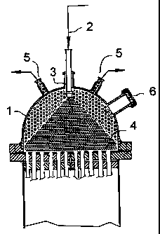
Figure 1 is a sectional side view of the apparatus according to the invention,
and
Figure 2 is a sectional side view of another embodiment of the apparatus
according to the
20 invention.
Detailed description
The invention will be described in more detail below, with reference to the
accompanying
drawing. I is a dome-shaped top of a falling film evaporator. The evaporator
resembles a
25 tube and shell heat exchanger placed in a vertical position. The feed-water
is delivered
through line 2 where it can be in a pre-heated state of, for example,. 120 C.
In line 2, the
pressure is preferably about 0.3 to about 6 bar higher than the pressure of
the clean vapour
to be produced.
30 The nozzle 3 is selected to provide, in the pressure range used, a hit
pattern that
substantially corresponds to the shape and size of the tube end plane 4.
Suitable nozzles
meeting the pressure and temperature requirements are commercially available.
In this

CA 02349166 2001-05-07
WO 00/27494 PCT/F199/00928
4
embodiment, the nozzle is placed in a symmetrically perpendicular position
above the tube
end plane but it can also be disposed in other ways. Further, more than one
spraying device
can be employed in order to achieve an even hit pattern. When the heated water
is
discharged from the nozzle 3 as a spray of droplets, the gases dissolved in
the water
separate quickly from the droplets and leave through the outlets 5 together
with a small
quantity of carrier vapour. The degassed droplets of water are distributed
evenly into the
evaporator tube assembly, and, in contrast to conventional evaporators, a
perforated plate
or another kind of distributing plate is not necessarily needed above the tube
end plane 4.
The water reaches the tube ends in a very short time, as a result of which the
transfer of
/o heat from the tube wall to the water starts practically immediately.
The distance between the nozzle 3 and the tube end plane 4 is preferably about
half the
diameter of the plane 4. The apparatus can be provided with a sight glass 6.
1s Preferably, the separated gases and the carrier steam are led into a heat
exchanger where
the thermal energy thereof is utilised for pre-heating the feed-water.
In the embodiment shown in Figure 2, the apparatus is further provided with a
trough 7 that
has a perforated bottom and that is arranged above the tube end plane 4 by
means of a
spacer 8. In this embodiment, a thin layer of water, from which gases still
can separate
before the water moves to the ends of the evaporator tubes through the bottom
holes of the
trough, accumulates in the trough 7.

Representative Drawing
A single figure which represents the drawing illustrating the invention.
Administrative Status

2024-08-01:As part of the Next Generation Patents (NGP) transition, the Canadian Patents Database (CPD) now contains a more detailed Event History, which replicates the Event Log of our new back-office solution.

Please note that "Inactive:" events refers to events no longer in use in our new back-office solution.

For a clearer understanding of the status of the application/patent presented on this page, the site Disclaimer , as well as the definitions for Patent , Event History , Maintenance Fee  and Payment History  should be consulted.

Event History

Description Date
Inactive: Expired (new Act pat) 2019-11-08
Common Representative Appointed 2019-10-30
Grant by Issuance 2008-02-19
Inactive: Cover page published 2008-02-18
Inactive: Final fee received 2007-12-07
Pre-grant 2007-12-07
Notice of Allowance is Issued 2007-09-04
Letter Sent 2007-09-04
Notice of Allowance is Issued 2007-09-04
Inactive: Approved for allowance (AFA) 2007-08-09
Amendment Received - Voluntary Amendment 2007-06-14
Inactive: S.30(2) Rules - Examiner requisition 2007-04-23
Inactive: IPC from MCD 2006-03-12
Letter Sent 2004-09-14
Request for Examination Received 2004-08-25
Request for Examination Requirements Determined Compliant 2004-08-25
All Requirements for Examination Determined Compliant 2004-08-25
Inactive: Cover page published 2001-09-19
Inactive: First IPC assigned 2001-08-07
Inactive: Notice - National entry - No RFE 2001-07-18
Letter Sent 2001-07-18
Application Received - PCT 2001-06-30
Amendment Received - Voluntary Amendment 2001-05-07
Application Published (Open to Public Inspection) 2000-05-18

Abandonment History

There is no abandonment history.

Maintenance Fee

The last payment was received on 2007-10-19

Note : If the full payment has not been received on or before the date indicated, a further fee may be required which may be one of the following

  • the reinstatement fee;
  • the late payment fee; or
  • additional fee to reverse deemed expiry.

Patent fees are adjusted on the 1st of January every year. The amounts above are the current amounts if received by December 31 of the current year.
Please refer to the CIPO Patent Fees web page to see all current fee amounts.

Owners on Record

Note: Records showing the ownership history in alphabetical order.

Current Owners on Record
STERIS EUROPE, INC. SUOMEN SIVULIIKE
Past Owners on Record
MAURI SALMISUO
Past Owners that do not appear in the "Owners on Record" listing will appear in other documentation within the application.
Documents

To view selected files, please enter reCAPTCHA code :


To view images, click a link in the Document Description column. To download the documents, select one or more checkboxes in the first column and then click the "Download Selected in PDF format (Zip Archive)" or the "Download Selected as Single PDF" button.

List of published and non-published patent-specific documents on the CPD .

If you have any difficulty accessing content, you can call the Client Service Centre at 1-866-997-1936 or send them an e-mail at CIPO Client Service Centre.


Document
Description 
Date
(yyyy-mm-dd) 
Number of pages   Size of Image (KB) 
Representative drawing 2001-08-22 1 15
Abstract 2001-05-06 1 67
Description 2001-05-06 4 188
Claims 2001-05-06 1 35
Drawings 2001-05-06 2 54
Abstract 2001-05-07 1 21
Claims 2001-05-07 3 99
Description 2007-06-13 4 186
Claims 2007-06-13 4 132
Representative drawing 2008-01-29 1 16
Reminder of maintenance fee due 2001-07-17 1 112
Notice of National Entry 2001-07-17 1 194
Courtesy - Certificate of registration (related document(s)) 2001-07-17 1 112
Reminder - Request for Examination 2004-07-11 1 117
Acknowledgement of Request for Examination 2004-09-13 1 185
Commissioner's Notice - Application Found Allowable 2007-09-03 1 164
PCT 2001-05-06 12 481
Fees 2003-09-17 1 36
Fees 2002-09-22 1 40
Fees 2001-09-18 1 37
Fees 2004-09-21 1 37
Fees 2005-10-26 1 38
Fees 2006-10-18 1 49
Correspondence 2007-12-06 1 44
Fees 2007-10-18 1 48