Note: Descriptions are shown in the official language in which they were submitted.
CA 02349364 2001-05-31
UNIVERSAL ATTACHMENT FOR CHILD CAR SEAT
The invention relates broadly to a child car seat for the protection and
restraint of a child
or infant while in a vehicle. More specifically, the invention relates to a
convertible car seat
having an improved universal attachment that provides convenient and effective
relocation of the
universal attachment for converting between a rearward facing and forward
facing child car seat
restraint.
BACKGROUND OF THE INVENTION
Vehicles, such as cars and vans, are presently equipped with occupant
restraining seat
belts installed by manufacturers of automobiles. While such seat belts are
adequate for
restraining adults in the event of a sudden stop, collision or other
emergency, most are inadequate
for protecting of small children and infants. As a result, a variety of
specially designed child
restraint devices have been designed and developed and are in widespread use
today. Child car
seats are indeed required by all states as a matter of law for use with
infants and children who are
of such size that a standard vehicle seat belt does not afford adequate
protection. Conventional
child car seats typically utilize the vehicle seat belt provided by the
vehicle manufacturer to
secure the child seat to the vehicle.
Most vehicles today come equipped with a three-point seat belt system, which
is either
formed from a lap belt and a shoulder harness joined together in a non-movable
latch plate or one
continuous belt having a movable or dropping latch plate separating the lap
belt portion from the
shoulder harness portion. In either configuration, the latch plate is coupled
together at one end for
releasable securement by the wearer to a buckle at a first fixed point on the
car seat adjacent the
CA 02349364 2001-05-31
wearer. The lower belt is the horizontal lap belt extending over the wearer's
lap to an adjacent
second fixed point. The second or shoulder belt extends transversely from the
buckle or anchor,
angling upwardly across the wearer's chest and shoulder, to an elevated fixed
third point.
Convertible child car seats, i.e., seats capable of being used in a rear-
facing or forward
facing orientation, are well known in the field. Depending on the desired
orientation, the vehicle
seat belt must generally be threaded through the child car seat in a different
way to securely
fasten the seat to the vehicle. See, for example, Kain, U.S. Pat. No.
4,764,999. The improper
installation of a child car seat in a vehicle, in either orientation, is a
very real possibility. It is a
matter of law in all states that a child weighing less than 20 pounds (or
generally one year of age)
must be placed in a child car seat secured in a vehicle in a rear-facing, more
reclined direction
until their body develops sufficiently and can withstand the forces involved
in a crash when
forward facing. Once the child weighs more than 20 pounds, the child may be
secured in the car
seat positioned in a forward-facing, more upright orientation.
New Federal safety standards under FMVSS 213 and 225 now require performance
that
mandates a tether system that secures the child car seat to the vehicle frame.
Typically, three
anchor points are provided by the vehicle manufacturer: one point located
between the seat back
of the vehicle rear seat and the vehicle parcel shelf, and two points located
at or near the seat
bight (i.e., the junction of the vehicle seat bottom and the vehicle seat
back). A center tether is
secured to the vehicle anchor located on the rear parcel shelf. Left and right
side tethers are
secured to the vehicle anchors located at or near the seat bight. This tether
anchoring system
permits the child car seat to be secured to hard points of the vehicle without
relying on the
vehicle's seat belts. Standard FMVSS225 further requires that child car seats
must be capable of
attaching to a vehicle's permanent anchors, as well as the vehicle seat belts.
2
CA 02349364 2001-05-31
It is known to provide a car seat tether system with one set of attachments to
accommodate a forward-facing position and another set of attachments to
accommodate a
rearward-facing position for the child car seat. However, the known
convertible child car seats
which provide a tether anchoring system that are convertible between a forward-
facing and
rearward-facing position suffer from one or more of following drawbacks. The
seats are either
complicated to operate, expensive to manufacture, or do not provide a
restraint configuration
with ease of conversion between forward and rearward positions. Some
convertible child car
seats require tools to convert the tether anchoring system between the two
positions. Other
convertible child car seats may pivot the tether about a center point without
changing the position
of the tether on the car seat.
In view of the foregoing disadvantages and drawbacks in the known convertible
car seats
utilizing a tether system, there is a need for a convertible car seat that is
cost effective, easily
converted between the forward-facing and rearward-facing positions, and that
provides a reliable
restraint for both rearward and forward car seat positions.
SUMMARY OF THE INVENTION
The needs identified above are met, and the shortcomings of prior art car seat
designs
overcome by the car seat of the present invention. In one aspect, the present
invention provides a
child restraint for mounting in a passenger seat of a vehicle, the child
restraint including a seat
body having a child support area disposed on an upper surface thereof and left
and right elongate
frame members extending from the upper seat back portion to the seat body
forward end along
the respective left and right sides of the seat body. The child restraint
further includes left and
right anchor attachments for securing the seat body to the left and right
vehicle anchors, each of
CA 02349364 2001-05-31
the left and right anchor attachments including an attachment end coupled to
the respective left
and right elongate frame members, and an engagement end for connecting the
left and right
anchor attachments to the respective left and right vehicle anchors located at
the vehicle seat
bight, wherein the attachment end of the left and right anchor attachment is
positionable along
the respective left and right elongate frame members between a forward anchor
point proximate
the forward end for configuring the seat body as a rearward facing car seat
and a rearward anchor
point proximate the upper back portion for configuring the seat body as a
forward facing car seat.
Bars may be used as left and right elongate frame members, such as tubular
shaped bars.
The elongate frame members may also correspond to a support structure defining
a continuous
tubular frame of the car seat or a frame member defining a seatbelt pathway
for a vehicle seat
belt restraint.
The left and right anchor attachments may correspond to a left and right strap
each having
a first and second end, the first end being secured to the respective left and
right elongate frame
members and the second end being connected to a latching member for securing
the seat body to
the respective left and right vehicle anchor. In one particular embodiment,
the left and right strap
are secured by forming a loop around the respective left and right elongate
frame member so as
to provide slidably positionable straps for configuring between the forward
and rearward facing
car seat.
In another aspect of the invention, a child car seat is configurable as both a
rearward and
forward facing car seat and securable to the left and right vehicle anchors
and includes a seat
body, a left and right tether, each of which including a first end adapted for
releasably securing
the left and right tether at the respective left and right vehicle anchor and
a second end fixedly
retaining the left and right tether to left and right anchoring members fixed
to the seat body,
4
CA 02349364 2001-05-31
wherein the left and right tether are secured to the respective left and right
vehicle anchor and
extend from the left and right vehicle anchor to the forward anchoring point
when the seat body
is configured as the rearward facing car seat, and wherein the left and right
tether are secured to
the respective left and right vehicle anchor and extend from the left and
right vehicle anchor to
the rearward anchor point when the seat body is configured as the forward
facing car seat.
In another aspect of the invention there is provided a method for converting a
child car
seat from a forward facing child car seat to a rearward facing child car seat,
the method including
the steps of releasing a latching end of each of a left and right tether from
the respective left and
right vehicle anchors rotating the seat body from a rearward facing to a
forward facing position
on the vehicle seat, sliding the coupling end of each of the left and right
tether along the
respective left and right anchoring member so as to re-position the coupling
end from the first
position to the second position, and attaching the latching end of each of the
left and right tether
to the respective left and right vehicle anchor.
Additional features and advantages of the invention will be set forth or be
apparent from
the description that follows. The features and advantages of the invention
will be realized and
attained by the structures and methods particularly pointed out in the written
description and
claims hereof as well as the appended drawings.
It is to be understood that both the foregoing general description and the
following
detailed description are exemplary and explanatory and are intended to provide
further
explanation without limiting the scope of the invention as claimed.
BRIEF DESCRIPTION OF THE DRAWINGS
The accompanying drawings, which are included to provide a further
understanding of the
CA 02349364 2001-05-31
invention, are incorporated in and constitute a part of this specification,
illustrate preferred
embodiments of the invention and together with the description serve to
explain the principles of
the invention. In the drawings:
FIG. 1 is a front perspective view of a preferred convertible child car seat
including an
anchoring restraint system constructed in accordance with the principles of
the invention.
FIG. 2 is a rear perspective view of the child car seat of FIG. 1 showing a
center and one
side anchoring attachment in a storage position.
FIG. 3 is an exploded perspective view of the child car seat of FIG. 2.
FIGS. 4 and 5 are perspective and side views of the child car seat of FIG. 1
in a
forward-facing orientation secured to the vehicle anchors located at the seat
bight and rear parcel
shelf.
FIGS. 6 and 7 are perspective and side views of the child car seat of FIG. 1
in a
rear-facing orientation secured to the vehicle anchors located at the seat
bight.
FIGS. 8a-8b are top and side views, respectively, of one embodiment of an
anchoring
restraint of the invention.
DETAILED DESCRIPTION
Reference will now be made in detail to presently preferred embodiments of the
invention, examples of which are illustrated in the accompanying drawings. As
depicted in
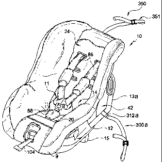
FIGS. 1-3, a preferred embodiment of a child restraining system includes a
unitary plastic shell or
main body 12, an attached child restraint harness 1 l, a pair of tubes 13a,
13b, a rear leg or
kickstand 15, a cushion 9, side anchoring attachments 300a, 300b, and a center
anchoring
attachment 350. Car seat 10 may be used as a forward or rearward facing car
seat securable in
vehicle seat using a vehicle supplied lap and shoulder belt restraint. Such a
use is described in
6
CA 02349364 2003-09-05
U.S. Pat. No. 5,957,531. In the preferred embodiment of the invention, car
seat 10 is adapted as
a forward or rearward facing car seat securable to the vehicle seat by a two
and three point
anchor restraint system.
The anchoring restraint system of the preferred embodiment includes a pair of
side anchor
attachments 300a, 300b coupled to tubes 13a, 13b of the car seat 10 in a such
a manner as to
allow repositioning of the anchor attachment 300 to accommodate a forward
facing car seat use,
FIGS. 4 and 5, and a rearward facing car seat use, FIGS. 6 and 7. Preferably,
anchor attachments
300a, 300b include a strap or webbing 308. Attached at one end of the side
anchoring attachment
300 is an engagement device 301 that is received in the vehicle supplied
permanent anchor 315.
The strap attachment to the car seat defines a forward facing anchor point 320
and a rearward
facing anchor point 322 located near the front and rear ends of the car seat
10, respectively. In
the forward facing position, a center anchor attachment 350 including a strap
357 and a center
engagement device 351 receivable in the vehicle supplied center permanent
anchor 360 is
provided as an additional restraint. For rearward facing car seat use, it is
preferred to use only the
side anchor attachments 300a, 300b, although the center anchor attachment 350
may also be
used. FIGS, 4-7 illustrate the forward facing anchor point 320 and rearward
facing anchor point
322 for the child restraining system 10 of the preferred embodiment. Side
anchor attachments
300a, 300b are adapted for being slidable along tubes 13a, 13b to allow
convenient placement of
the anchor attachments 300a, 300b relative to the vehicle seat bight 198
without the need for
reattachment or significant re-adjustment of the anchor attachments 300 when
converting
between forward and rearward facing positions. This adjustment feature of the
side anchor
attachments 300 also does not require that a user remove the anchor attachment
and then re-
attach the anchor attachment when converting between forward facing and
rearward facing
7
CA 02349364 2001-05-31
positions. Additionally, the tether anchor system of the preferred embodiment
provides a
convenient and easy to use system that varies the car seat anchor points 320,
322 so as to reduce
the length of the anchor attachments 300 needed to reach the vehicle anchor
points in both
forward facing and rearward facing positions and, furthermore, allows
positioning of the anchor
attachment at an optimal angle for load transfers to and from the vehicle to
car seat 10. This
aspect of the invention also allows a relatively short anchor attachment for
forward and rearward
car seat uses, thereby reducing the instances of excessive, unwanted motion of
the car seat caused
by the minimum fully tightened length being too long to obtain a tight fit in
some vehicles. This
short anchor attachment length will ensure the child restraint is optimally
compatible to the wide
variety of available vehicles.
The major components of the car seat of the preferred embodiment will now be
described
with reference to FIGS. 1-3. The main body 12 has a generally arcuate or
curved child support
area 14 to receive a child or infant in a sitting position. The child support
area 14 of the main
body 12 includes a lower seat portion 20 upon which a child may sit, and an
upper back portion
24 for supporting the back of a child. The main body 12 also includes an
exterior surface 26
adapted to contact the vehicle seating surface. In particular, the exterior
surface 26 of the main
body 12 includes an exterior upper back portion 28 adapted to contact the
vehicle seat back and a
lower base portion 30 adapted to contact the vehicle seat bottom or seat pan.
The main seat body
12 also includes a pair of laterally-spaced sidewalls 34a, 34b to prevent a
child seated therein
from excessive lateral movement. The main body 12 and cushion 9 may have one
or more slots
or grommets 40 therethrough to accommodate harness adjustment fixtures. The
car seat includes
a unitary plastic main body having an energy absorbing foam insert.
The placement and securing of a child in car seat 10, including the operation
of the
8
CA 02349364 2003-09-05
attached child harness 11, kickstand 15 for adjusting the inclination of the
car seat
between forward and rearward facing car seat uses, and the securing of the car
seat with
a vehicle supplied lap and shoulder belts, is the same as described in U.S.
Pat. No.
5,957,531. The child restraint harness 11 is coupled to car seat 10 to
restrain a child in
child support area 14. The child restraint harness 11 includes a pair of
shoulder straps
86 coupled to a crotch strap 88. Shoulder straps 86 are preferably attached to
crotch strap 88 by means of buckles and latch plates. Shoulder straps 86 and
the crotch strap 88
cooperate to provide a five-point child restraint to retain the child in child
support area 14. A
tensioning strap 104 is permanently attached to a three-way connector (not
shown) to lock
shoulder straps 86 in position. As shown in FIGS. 2-5, car seat 10 further
includes a pivotally
attached rear leg or kickstand 15 which functions as a seat recline adjuster.
In the forward facing
orientation, rear leg 15 is pivoted out such that a distal end extends away
from seat body 12 and
into the vehicle seat, thereby providing proper positioning and a more secure
fit. The extended
position of rear leg 15 allows the seat to have a more upright position, as
opposed to a more
reclined position, which is preferable for a toddler or young child who is
more alert and active. In
the rearward facing orientation, rear leg 15 is pivoted to retract into or
below seat body 12 so that
the child seat assumes a more reclined position, which is preferable for an
infant who does not
generally have adequate muscle strength to hold up his/her head.
As can be seen in FIGS. 4-7, car seat 10 is adapted to be positioned upon a
vehicle seat
190, in either a rearward facing or forward facing orientation. In the forward
facing orientation,
exterior upper back portion 28 contacts generally vertical back support
surface 192 of the vehicle
seat, and lower base portion 30 contacts vehicle seat bottom 194 or pan. In
the rearward facing
orientation, exterior upper back portion 28 faces away from back support
surface 192 of the
9
CA 02349364 2003-09-05
vehicle seat, and lower base portion 30 contacts the vehicle seat bottom 194
or pan. The
preferred embodiment of the car seat includes a continuous loop of steel
tubing 13 having two
substantially horizontal transverse portions 45, 47 and two substantially
downwardly and
forwardly extending side portions 41. The side portions 41 preferably include
a bend 17
S conforming generally to the shape of the seat. Transverse portions 45, 47
extend through
sidewalls 34a, 34b and are securely attached to, or fitted through, the upper
and lower portions of
the seat. The upper transverse portion 45 provides strength and support to the
seat. The lower
transverse portion 47 provides support and structural integrity and also
provides a place to
securely mount the child restraint harness 11.
The downwardly extending tube portions 41 preferably extend diagonally
downward
along the sides of the car seat 10, toward a front lower portion of the seat,
and are at a spaced
relationship thereto, thus creating a passageway 42 between the tubes 13 and
the sidewalls 34a, 34b
of car seat 10. In the preferred embodiment, the middle portion of the side
walls 34a, 34b, or that
portion located beneath tubes 13, is cut away to allow a more rounded
transition from the side wall
34a, 34b to exterior upper back portion 28 and allows greater access by a hand
or arm for easier
installation of a vehicle seat belt. In the rearward facing position, the
vehicle seat belt is passed
through one of the openings 80 in the side walls 34a, 34b of the seat 10, over
the seating surface 62
and down through the opening on the opposite sidewall 34a, 34b. In the forward
facing position, the
vehicle seat belt pathway extends from the vehicle seat 190 partially around
one of the tubes 13a,
13b, preferably just below the bend 17, through the adjacent passageway 42,
behind the exterior
upper back portion 28, through the opposite passageway 42 and then partially
around the other tube
13 to engage a buckle portion of the seat belt. Preferably, the entry points
are disposed along a line
that passes through, or near, the center of gravity of the child seated in the
car seat. This
CA 02349364 2001-05-31
placement of the entry points reduces pitching moments applied to the car seat
during an impact.
In the preferred embodiment, side anchoring attachments 300a, 300b, and a
center
anchoring attachment 350 are provided so that car seat 10 may be restrained
either by the vehicle
seat belt or the vehicle permanent anchors. For both side anchoring
attachments 300 and center
anchoring attachment 350, flexible straps are preferably used to transfer
loads between the
anchor points (e.g., anchor points 320, 322 and center anchor point 362) and
the vehicle
permanent anchors 315, 360. Side anchoring attachments 300 include an
engagement device 301
located at one end for engaging the vehicle permanent anchor 315 and a car
seat anchor coupling
312 located at the opposite end for engaging car seat 10. Vehicle permanent
anchor 31 S is
provided by the vehicle manufacturer and includes an anchoring device such as
a steel plate with
an aperture or a loop. Engagement device 301 preferably includes a hook 302, a
slide bar adjuster
304, a spring clip 306, an anchor coupling 312 is preferably a loop formed at
the opposite end of
strap 308, and a loop 310. As shown in FIGS. 8a, 8b, hook 302 is attached to
flexible strap 308
by looping strap 308 through an aperture 303 in the hook 302 and around the
slide bar adjuster
304. Flexible strap 308 may be made from any material known in the art, for
example, webbing
made from synthetic materials, like polyester or nylon, and such materials
that are generally
known. Spring clip 306 reduces the chance of hook 302 accidentally disengaging
from loop 210
during use.
A variety of vehicle anchor devices may be used without departing from the
scope of the
invention; for example, a push button release buckle may be used as a vehicle
engagement
device, or any other off the-shelf or future developed devices for securing a
child car seat to a
vehicle anchorage. However, vehicle engagement device 301 is preferred because
it is a
relatively low cost device to manufacture, as opposed to the more expensive
buckle attachments
CA 02349364 2001-05-31
used in other known car seats, automobiles and airline seats. Slide bar
adjuster 304 is made from
a rigid material such as stamped steel and fornied to allow strap 308 to pass
through apertures
305 in adjuster 304. Slide bar adjuster 304 may be shaped to allow leverage in
rotating adjuster
304, as shown in FIGS. 8a, 8b. Anchoring attachments 300 are tightened when
the tail end 309
of the strap 308 is pulled as shown in the direction B in FIG. 8b. When hook
302 is put in
tension, slide bar adjuster 304 pinches strap 308 against the lower edge of
hook 302 to prevent
loosening. To loosen strap 308, slide bar adjuster 304 is rotated upwards in
direction A, as shown
in FIG. 8b, thereby releasing strap 308. Slide bar adjuster 304 provides a
shorter assembled
length which allows anchor attachment 300 to be used in situations where the
point of attachment
on the car seat and the vehicle anchor point are in close proximity. This
feature of engagement
device 301 is particularly desirable in situations where the assembled length
of the latching
system makes it difficult, if not impossible to properly secure and/or adjust
the latching system in
vehicles which provide restricted access to the vehicle permanent anchor, the
car seat tether
device, or where the car seat anchor point and vehicle anchor point are in
close proximity to each
other. Center engagement device 351 of center anchoring attachment 350 is
constructed in a
similar fashion to that of the engagement device 301 of the side anchoring
attachments 300
discussed above.
As noted above, car seat anchor couplings 312a, 312b of the side anchoring
attachments
300a, 300b are located along tubes 13a, 13b and are positionable between
forward facing and
rearward facing anchor points 320, 322, respectively. As shown in FIG. 1, car
seat anchor
coupling 312 is constructed by forming a loop 310 over tube 13. Loop 3 10a is
formed by sewing
an end of strap 308 back on itself; however, loop 310 may take on any form
known in the art,
such as a tube or other device capable of being repositioned along tube 13.
Loop 310 may be
12
CA 02349364 2003-09-05
formed by folding strap 308 over and fixing an end of strap 308 to itself
with, for example,
sewing, rivets, bolt system, clamp, or the like. With this construction, strap
308 easily slides
over the length of tube 13 to provide proper positioning of the anchor
attachments 300 for
forward and rearward car seat use, as illustrated in FIGS. 4-7. Thus, tube 13
serves as both a seat
belt pathway for securing the car seat using the vehicle supplied lap and
shoulder belts (as noted
above), as well as a plurality of anchor points for side anchor attachments
300.
Center anchor attachment 350 also includes a strap 357 and a center engagement
device
351. Thus, center engagement device 351 includes a hook 352 with a spring clip
356, and an
adjustable slide bar 354 operated in a similar method to that of engagement
device 301 of side
anchor attachments 300. Center anchor attachment 350 is attached to the
substantially horizontal
transverse portion 45 of the tube 13 with a loop 358, as shown in FIG. 3.
Strap 357 runs up exterior
upper back portion 28 against main body 12 and through an aperture 366.
Referring to FIG. 2, storage devices are provided to store anchor attachments
300, 350
when the vehicle supplied seat belts are used to secure the car seat. Center
anchor attachment
350 is folded and secured to the upper back portion of main body 12 using a
storage device 376
which may include any method well known in the art, e.g., hook and loop
fastener. A side
anchor stowage unit 370 is provided to stow the side anchoring attachments
300. Side anchor
stowage unit 370 is disposed on an exterior back plate 368 located on exterior
upper back portion
28. Side anchor stowage unit 370 includes a raised portion having a circular
apertwe and a
plurality of side attachment apertures 374 for receiving hooks 302 of the
engagement devices 301
to secwe side anchor attachments 300 in a stowed position.
In use, the position of the engagement devices 301 of side anchor attachment
300 is
adjusted depending on whether the car seat is used in a forward or rearward
facing position. In
13
CA 02349364 2001-05-31
the forward facing orientation, FIGS. 4-5, car seat anchor point 320 is
positioned by bend 17 of
tube 13. The vehicle permanent anchors 315 are located between seat back
support surface 192
and seat bottom 194, or seat bight 198. The center vehicle permanent anchor
360 is located at
the rear parcel shelf or a fixed point behind the vehicle seat. Preferably,
car seat anchor points
320 of side anchoring attachments 300 are positioned close to the seated
child's center of gravity
and car seat anchor point 320. This placement of car seat anchor reduces
pitching moments
applied to the car seat during an impact. Also, bend 17 is preferably
positioned on tubes 13 so
that anchor attachments 300 extend at about a 45 degree angle from the seat
bight 198 when
engaging tubes 13 just below the bend 17. In the forward facing orientation,
rear leg 1 S is rotated
down and outwardly from the bottom of the car seat 10 to extend into the bight
198 of the vehicle
seat 190. In the rearward facing orientation, FIGS. 6-7, side anchor
attachments 300 are slid
forward on tube 13 and attached to permanent vehicle anchors 31 S. FIG. 2
shows anchor
attachment 300a in the rearward facing car seat position. Car seat anchor
point 322 is located on
tube 13 proximate a point where tube 13 enters the forward end of main body
12. In the rearward
facing orientation, rear leg 15 is rotated into main body 12 such that the
seat assumes a more
reclined position.
14