Note: Descriptions are shown in the official language in which they were submitted.
Our Ref.: AB-313 (F2001-026)
- 1 -
PLASTIC OPTICAL FIBER
The present invention relates to a graded index
plastic optical fiber having a small bending loss and
being excellent in heat resistance and heat and humidity
resistance.
Known as a graded index plastic optical fiber is a
plastic optical fiber having a graded index distribution
structure comprising, as a matrix, a non-crystalline
fluoropolymer having substantially no C-H bond and a
1o substance having a different refractive index from the
matrix, distributed with a concentration gradient in a
radial direction (see JP-A-8-5848). Further, JP-A-8-
304636 discloses an optical fiber having a polymer with a
refractive index lower than matrix, provided on the outer
z5 circumference of the matrix, in order to avoid an
increase of the attenuation loss by bending in such a
graded index optical fiber.
The conventional graded index optical fiber having
such a low refractive index polymer provided on the outer
2o circumference, has had a problem that the attenuation
CA 02349817 2001-06-07
- 2 -
loss increases when it is subjected to a heat
resistance/heat and humidity resistance tests such as
long term heat resistance test (70°C for 1,000 hours), a
temperature cycle test (70°C/-20°C x 10 times) or a heat
and humidity cycle test (65°C, humidity of 95%/-10°C x 10
times).
The present inventors have analyzed the fibers after
the heat cycle test and the heat and humidity cycle test,
and as a result, have found that peellTlg which takes
1o place between the outer layer made of t:he low refractive
index polymer and the inner layer having a graded index
distribution formed, is the cause for an increase of the
attenuation loss.
On the basis of the recognition of such problems,
the present inventors have conducted an extensive study
and as a result have found that in order to improve the
adhesion between the inner layer and the outer layer, it
is effective to employ a polymer having a high affinity
to the polymer constituting the matrix of the inner
layer, as the low refractive index material of the outer
layer. Namely, the present invention i.s to provide a
graded index optical fiber anew wherein an outer layer is
formed outside the inner layer having a graded index
formed, by means of a polymer having a refractive index
lower than the refractive index of the outermost portion
of the inner layer and a good adhesive property, to
provide an optical fiber having an increase of the
CA 02349817 2001-06-07
- 3 -
attenuation loss by bending reduced whale maintaining the
heat resistance and the heat and humidity resistance.
The present invention is the following invention based on
such a discovery.
A plastic optical fiber which is a graded index
optical fiber having a concentric inner/outer at least
two layer structure, wherein the inner layer has a graded
index structure made of a non-crystalline fluoropolymer
(a) having substantially no C-H bond, <~nd the outer layer
1o has a refractive index lower than the refractive index of
the outermost portion of the inner layer and is made of a
fluoropolymer material (c) selected from the following 1)
and 2):
1) a fluoropolymer (d) containing the same
polymerized units as the polymerized units in the
f luoropolymer ( a ) , arid
2) a mixture (f) of a fluoropolyme.r (a) with another
fluoropolymer (e).
In the optical fiber of the present invention, in
order for the fluoropolymer material (c) to have a high
adhesive property with the fluoropolymer (a) and in order
not to let the heat resistance and the heat and humidity
resistance of the optical fiber deteriorate, the glass
transition temperature Tgc of the fluoropolymer material
(c) is preferably 70"C<Tgc<Tga+30°C, where Tga is the
glass transition temperature of the fluoropolymer (a).
Further, the fluoropolymer (d) preferably contains at
CA 02349817 2001-06-07
- 4 -
least 30 mol% of the same polymerized units as the
polymerized units in the fluoropolymer (a). Here, the
polymerized units in the present invention are meant for
repeating units in a polymer formed by a polymerization
reaction of a monomer.
Further, in order not to let the attenuation loss of
the optical fiber increase, the refractive index of the
fluoropolymer material (c) is preferably lower by at
least 0.03 than the refractive index of the outermost
1o portion of the inner layer. Here, the refractive index
in the present invention is a refractive index against
sodium D line spectrum.
In the optical fiber of the present. invention, its
inner layer is preferably an inner layer which contains
the fluoropolymer (a) as a matrix, and a substance (b)
having a different refractive index is distributed in the
matrix to form the graded index structure. As the
fluoropolymer (a), a fluoropolymer having a ring
structure in its main chain as disclosed in the above-
2o mentioned prior art is preferred. Likewise, the
fluoropolymer (d) and the fluoropolymer (e) are
preferably fluoropolymers having ring structures in their
main chains. Further, the optical fiber of the present
invention preferably has a protective coating layer made
of a synthetic resin provided outside the outer layer.
As such a synthetic resin, a thermoplastic resin made of
a polymer other than the fluoropolymer (a), the
CA 02349817 2001-06-07
- 5 -
fluoropolymer (d) and the fluoropolymer (e), which has
heretofore been used or proposed to be used as a
protective coating layer for an optical fiber, is
preferred.
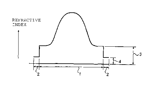
In the accompanying drawings:
Fig. 1 is a graph showing the refractive index
distribution in a radial direction in the cross-section
of an optical fiber of the present invention.
Fig. 2 is a graph showing the refractive index
to distribution in a radial direction in the cross-section
of an optical fiber of the present invention.
The reference numerals in the Figures have the
following meanings:
1: inner layer
s5 2: outer layer
3: refractive index level of the outermost portion
of the inner layer
4: refractive index level of the outer layer
The refractive index distributions in a radial
2o direction of the optical fibers of the present invention
are shown in Figs. 1(A) and (B) and Figs. 2(C) and (D).
The abscissa represents the diameter of the optical
fiber, and the ordinate represents the refractive index.
Within the inner layer (range (1)), the optical fiber has
25 a refractive index distribution such that the refractive
index is high at the center, and the refractive index
decreases as the position is apart from the center. The
CA 02349817 2001-06-07
- 6 -
refractive index of t:he outer layer (range (2)) is lower
than the refractive index of the outermost portion of the
inner layer. The refractive index distribution in the
inner layer may be one showing a gentle distribution at
the peripheral portion as shown in Figs. 1(A) and (B) or
may be the one showing a parabolic distribution as shown
in Figs. (C) and (D). From the viewpoint such that the
band width is broad, one having the latter parabolic
refractive index distribution is preferred. On the other
so hand, the refractive index may have a distribution such
that it continuously lowers to the outermost portion of
the inner layer, as shown in Fig. 1(B) and Fig. 2(D), or
it may continuously lowers from the center to an
intermediate portion of the inner layer, and the inner
s5 layer outside thereof, has a constant refractive index,
as shown in Fig. 1(A) and Fig. 2(C). The outer layer in
Fig. 1(B) and Fig. 2(D) functions substantially as a clad
layer. Further, the portion where the refractive index
is constant in the inner layer as shown in Fig. 1(A) and
2o Fig. 2(C), functions as a clad layer, and the outer layer
functions as a second clad layer.
The refractive index of the outer layer is
preferably lower by at least 0.003 than the refractive
index of the outermost layer of the inner layer to reduce
25 the bending loss. The difference in the refractive index
is more preferably at. least 0.005. Further, the
numerical aperture NA which is calculated from the
CA 02349817 2001-06-07
2001. J~3O(j 139~33i~ T. S, INTERNATIONAL CORFORATION No, 1~2J P, 2/2
A
maxim,.im refractive index at the center portion and the
minimum refractive index at the out~i layer, is
prr~tarahly at least 0.20, more preferably at leant 0.23,
particularly preferably at last 0.25, In general. the
bending .LC).~~R 'VJ9Y1 PS C~P~IPnf_~ln~.'J upon the cor~ diameter of
an optical fiber, and the larger the ouie c~i~tmeter, the
larger the bending loss. The core diampfipr of the
optical fiber in the prc~cnt invention is not
parLi~ula~ly 111I11ted, but it is preferably at most 1,UUU
7n ym, more prQferably at most 500 pn, particularly
preferably at most 200 um. Further, the cute portion of
the optical fiber in the present inva~nt.inn is a portion
having a refractiv~ ind~x highex by at lca,t 5~k of the
difference Letweclz elm li~lm5l. refractive index in Lhe
inner layer and the lowest retrsr.l-.ivp index in the inner
layer than the lowest refractive index in the inner
layC~ .
The optical fiber of the pr~sent invention may
further have a protective coating layer vutsi~3.c l.xie outer
2u layer. ~hhe material for this protective coating layr~r is
not particularly limited so long as it is a synthetic
se5in, dnd it is possible to employ a thermoplastic resin
nr. a r~lr~ed product of a curable r~sin, which is a
material other tllalz the fluo~upolymer (a) , the
fliiorcpnlymPr (d) anti thR tluoropolymer (e). Among them,
a oynthetic resin is preferred which has heretutuie been
used or proposed r.o hP usPC7 as ~ protective coating layer
CA 02349817 2001-06-07
CA 02349817 2001-06-07
_ g _
for an optical fiber. When it is required to increase
the mechanical strength as a role of the protective
coating layer, it is required to be a :Layer having a
thickness of at least a certain level, and it is
preferred to employ a synthetic resin having high tensile
strength or modulus of elasticity. As the material for
the protective coating layer, a thermoplastic resin is
preferred, and particularly preferred :is an acrylic
resin, a polycarbonate resin or a cyclic polyolefin
to resin. Further, this protective coating layer may be of
a multilayer structure of two or more .Layers, of which
one layer may be made of a relatively soft thermoplastic
resin such as a vinyl chloride resin, a polyolefin resin,
a poly(vinylidene fluoride) resin or
ethylene/tetrafluoroethylene copolymer resin.
As a method for .forming a graded refractive index
distribution in the inner layer in the present invention,
it is preferred to employ a method wherein a
fluoropolymer (a) is used as the matrix, and a substance
(b) having a different refractive index is distributed in
the matrix to form a graded index distribution structure.
Otherwise, it may be a method wherein two or more
fluoromonomers capable of forming a polymer having the
refractive index changed depending upon the compositional
proportions for polymerization, are combined to form an
inner layer composed of a fluoropolymer (a) having the
compositional proportions for polymerization varied in
CA 02349817 2001-06-07
_ g _
the radial direction from the center. The fluoropolymer
(a) is required to be a non-crystalline fluoropolymer in
order to have a low attenuation loss, and it is required
to have a chemical structure having no C-H bond to make
optical communication in the near infr<~red wavelength
band possible. The substance (b) is likewise one soluble
in the fluoropolymer and it preferably has a chemical
structure having no C-H bond.
The fluoropolyme.r material (c) constituting the
outer layer is required to be a material having a
refractive index lower than the refractive index of the
outermost portion of the inner layer. The fluoropolymer
(d) contains the same polymerized units as the
polymerized units in the fluoropolymer (a). The mixture
(f) is a mixture of t=he fluoropolymer (a) with another
fluoropolymer (e). Here, the fluoropolymer (d) and the
fluoropolymer (e) may be the same polymer.
As the fluoropolymer (d) contains a larger amount of
the same polymerized units as the polymerized units in
2o the fluoropolymer (a) (hereinafter referred to as
polymerized units a), the adhesive property with the
fluoropolymer (a) is improved, and the heat resistance
and the heat and humidity resistance can more easily be
maintained, such being preferred. On the other hand, the
z5 difference in the refractive index between the two
fluoropolymers becomes small, and accordingly, in order
to maintain a predetermined difference in the refractive
CA 02349817 2001-06-07
- 10 -
index, the proportion of the polymerized units a in the
fluoropolymer (d) is inevitably limited. The polymerized
units a are not limited to one type of polymerized units,
and in a case where both fluoropolymers are copolymers,
two or more polymerized units may be common. The
proportion of the polymerized units a in the total
polymerized units in the fluoropolymer (d) is preferably
at least 20 mol%, particularly preferably at least 30
mol%. The upper limit is not particularly limited so
long as the predetermined difference in the refractive
index between the two fluoropolymers can be maintained,
but usually, it is 95 mol%, preferably 85 mol%. Further,
the fluoropolymer (d) is preferably optically
transparent, although the optical transparency is not
i5 necessarily essential. In order to increase the adhesive
property with the fluoropolymer (a), it: is preferably a
non-crystalline polymer. The polymerized units a are
preferably polymerized units having a fluoroaliphatic
ring structure as will be described hereinafter with
2o reference to the fluoropolymer (a).
Also in the case of the mixture (f), the proportion
of the fluoropolymer (a) contained in t:he mixture is
preferably high from the viewpoint of improvement of e.g.
the adhesive property, but in order to maintain the
25 predetermined difference in the refractive index from the
fluoropolymer (a), the proportion is inevitably limited.
The mixture (f) is preferably optically uniform and
CA 02349817 2001-06-07
- 11 -
highly transparent, but such is not necessarily
essential. On the other hand, the fluoropolymer (e) and
the fluoropolymer (a) are preferably uniformly miscible
polymers for the improvement of the adhesive property
with the inner layer. For such a purpose, the
fluoropolymer (e) is required to be a polymer having high
affinity with the fluoropolymer (a), and accordingly, it
is preferably a fluoropolymer containing polymerized
units a in the same manner as the above-mentioned
Zo fluoropolymer (d). Namely, the fluoropolymer (e) is
preferably the same one as the above-mentioned
fluoropolymer (d). However, the proportion of the
polymerized units a :in the fluoropolymer (e) may be
smaller than the above-mentioned preferred proportion of
the polymerized units a in the fluoropolymer (d).
Namely, as the fluoropolymer (e) is used as mixed with
the fluoropolymer (a), the adhesive property of the
mixture (f) to the inner layer is improved to such an
extent that the fluoropolymer (a) is present, even if the
2o proportion of the polymerized units a :in the
fluoropolymer (e) is small.
The proportion of the fluoropolyme:r (a) in the
mixture (f) is preferably at most 90 mass%, particularly
preferably at most 70 mass°s. If the proportion is too
much, the predetermined difference in the refractive
index between the inner layer and the outer layer can not
be maintained. There is no particular lower limit in its
CA 02349817 2001-06-07
- 12 -
proportion, because when the fluoropolymer (e) is the
fluoropolymer (d), the object can be accomplished even if
no fluoropolymer (a) is present, whereby the proportion
of the fluoropolymer (a) in the mixture (f) may be very
small. However, in order to further improve the adhesive
property, etc., it is preferably at least 5 mass%,
particularly preferably at least 10 mars%. If the
fluoropolymer (e) is not the fluoropolymer (d) (i.e. if
it contains no polymerized units a), the proportion of
to the fluoropolymer (a) in the mixture (f) is preferably at
least 10 mass%, particularly preferably at least 30
mass%.
The glass transition temperature Tgc of the
fluoropolymer material (c) is preferably
70°C<Tgc<Tga+30°C. If Tgc is lower than 70°C, a heat
deformation is likely to result, and the attenuation loss
tends to increase, and in the case of an optical fiber
having a protective coating layer formed, displacement is
likely to take place between the outer layer and the
2o protective coating layer during the temperature cycle of
high temperature and low temperature, whereby a
protrusion or a dent is likely to form at the end face of
the fiber. On the other hand, if Tgc is (Tga+30°C) or
higher, a difference in the shrinkage rate is likely to
form as between the inner layer and the outer layer
during cooling at the time of spinning of the optical
fiber, whereby a strain is likely to form in the inner
CA 02349817 2001-06-07
- 13 -
layer, which is likely to cause a scattering loss.
Accordingly, Tgc is preferably such that the difference
from Tga is within 10°C. Further, for the same reason,
the melt viscosity o:f the fluoropolyme:r material (c) is
preferably as close as possible to the melt viscosity of
the fluoropolymer (a) in the inner layer.
When the fluoropolymer material (c) is a mixture of
two or more polymers, and the two or more polymers are
sufficiently uniformly mixed, Tg of the mixture will be a
1o single Tg correspond.ing to the mass proportions of the
respective polymers. In such a case, t=his single Tg of
the mixture is the above-mentioned Tgc. However, if the
mixture is not suffir_iently uniform, Tg of the mixture
may appear as independent Tg (at least two Tg) based on
the respective polymers. In such a case, as the polymer
mixture in the present invention, Tg of each polymer is
preferably within the above-mentioned range.
The fluoropolymer material (c) is preferably a
material having no C-H bond, but "having no C-H bond" is
2o not necessarily essential. Namely, the fluoropolymer (d)
or the fluoropolymer (e) may be a polymer having a C-H
bond. The outer layer is not a portion where light is
mainly transmitted, but may suffice if it reflects light
leaked from the inner layer when the optical fiber is
bent. Accordingly, the fluoropolymer material (c) is not
substantially influential over the transmittance of light
having a wavelength, the absorption of which takes place
CA 02349817 2001-06-07
- 14 -
by the presence of a C-H bond. When the fluoropolymer
material (c) has a C~-H bond i.e. when the fluoropolymer
(d) or the fluoropol~~rmer (e) has a C-H bond, the
proportion of hydrogen atoms bonded to the carbon atoms
in the polymer is preferably at most 5 mass%,
particularly preferably at most 1 mass%. If the
proportion is too high, the refractive index of the
polymer increases, and the predetermined difference in
the refractive index from the inner layer can not be
1o maintained. As polymerized units having a C-H bond in
the fluoropolymer having a small amount of the C-H bond,
polymerized units derived from a monomer having one or
two fluorine atoms or chlorine atoms o:E the monomer for
the preparation of the fluoropolymer (a), which will be
s5 described hereinafter, substituted by hydrogen atoms,
may, for example, be mentioned.
In the present invention, the fluoropolymer (a) is
not particularly limited so long as it is a fluoropolymer
which is non-crystalline and which has substantially no
2o C-H bond where light absorption takes place with near
infrared light. However, preferred is a fluoropolymer
having a fluorine-containing aliphatic ring structure in
its main chain.
"Having a fluorine-containing aliphatic ring
25 structure in its main chain" means a structure wherein at
least one carbon atom constituting the aliphatic ring is
a carbon atom in a carbon chain constituting the main
CA 02349817 2001-06-07
- 15 -
chain, and a fluorine atom or a fluorine-containing group
is bonded to at least a part of carbon atoms constituting
the aliphatic rings. The atoms constituting the ring may
contain an oxygen atom or a nitrogen atom in addition to
carbon atoms. As a fluorine-containing aliphatic ring
structure, a fluorine-containing aliphatic ether ring
structure is more preferred.
The viscosity in the molten state of the
fluoropolymer (a) is preferably from 103 to 105 poise at
1o a melting temperature of from 200 to 300°C. If the melt
viscosity is too high, melt spinning tends to be
difficult, and further, diffusion of the substance (b)
which is required for the formation of the graded
refractive index distribution, tends to be difficult,
s5 whereby formation of the graded refractive index
distribution becomes difficult. On the other hand, if
the melt viscosity is too low, there will be a practical
problem. Namely, when it is exposed to a high
temperature when used as an optical transmission medium
2o for e.g. an electronic appliance or an automobile, it
will be softened, and the light transmitting performance
will deteriorate.
The number average molecular weight of the
fluoropolymer (a) is preferably from 1x10⁴ to 5x10⁶, more
25 preferably from 5x10⁴ to 1x10⁶. If the molecular weight
is too small, the heat resistance will be impaired, and
if it is too large, formation of an optical transmission
CA 02349817 2001-06-07
- 16 -
medium having a graded refractive index distribution,
will be difficult. When this molecular weight is
represented by an intrinsic viscosity [r~], the intrinsic
viscosity is preferably from 0.1 to 1.0, particularly
preferably from 0.2 to 0.5, in perfluoro(2-
butyltetrahydrofuranl (hereinafter referred to as PBTHF)
at 3 0°C .
The polymer having a fluorine-containing aliphatic
ring structure is preferably a polymer obtainable by
1o polymerizing a monomer having a fluorine-containing ring
structure (a monomer having a polymerizable double bond
between a carbon atom constituting the ring and a carbon
atom not-constituting the ring, or a monomer having a
polymerizable double bond between two carbon atoms
s5 constituting the ring), or a polymer having a fluorine-
containing aliphatic ring structure on its main chain,
obtainable by cyclic polymerization of a fluorine-
containing monomer having at least two polymerizable
double bonds.
zo The polymer having a fluorine-containing aliphatic
ring structure in its main chain, obtainable by
polymerizing a monomer having a fluorine-containing
aliphatic ring structure, is known, for example, in JP-B-
63-18964. Namely, a polymer having a fluorine-containing
25 aliphatic ring structure in its main chain can be
obtained by homopolymerization of a monomer having a
fluorine-containing aliphatic ring structure, such as
CA 02349817 2001-06-07
- 17 -
perfluoro(2,2-dimethyl-1,3-dioxol), or by copolymerizing
such a monomer with a radical-polymerizable monomer
containing no C-H bond.
The radical polymerizable monomer containing no C-H
bond is preferably a polyfluoroolefin having no C-H bond
or a vinyl ether type monomer having no C-H bond. The
polyfluoroolefin having no C-H bond, may, specifically,
be, for example, a polyfluoroolefin such as
tetrafluoroethylene, or a perhalopolyfluoroolefin such as
to chlorotrifluoroethylene. The polyfluoroolefin having no
C-H bond or the vinyl ether monomer hawing no C-H bond,
may, specifically, be, for example, a perfluoro(alkyl
vinyl ether), a perhalopolyfluoro(alkyl vinyl ether)
having some of fluorine atoms thereof substituted by
chlorine atoms, or a perfluoro{(alkoxyalkyl)vinyl ether}
having an etheric oxygen atom between the carbon atoms of
an alkyl group of the perfluoro(alkyl vinyl ether). The
carbon number of such a polyfluoroolefin is preferably
from 2 to 4, and the carbon number of the alkyl moiety
2o which may have an etheric oxygen atom, in the above-
mentioned vinyl ether monomer, is preferably at most 10.
The polymer having a fluorine-containing aliphatic
ring structure in its main chain, obtainable by cyclic
polymerization of a fluorine-containing monomer having at
least two polymerizable double bonds, is known, for
example, in JP-A-63-:?38111 or JP-A-63-'?38115. Namely, a
polymer having a fluorine-containing aliphatic ring
CA 02349817 2001-06-07
- 18 -
structure can be obtained by cyclic polymerization of a
monomer such as perfluoro(allyl vinyl ether) or
perfluoro(butenyl vinyl ether), or by copolymerizing such
a monomer with a radical polymerizable monomer such as
tetrafluoroethylene, chlorotrifluoroethylene or
perfluoro(methyl vinyl ether).
Further, a polymer having a fluorine-containing
aliphatic ring structure in its main chain, may be
obtained also by copolymerizing a monomer having a
1o fluorine-containing aliphatic ring structure such as
perfluoro(2,2-dimethyl-1,3-dioxol) with a fluorine
containing monomer having at least two polymerizable
double bonds such as perfluoro(allyl v:Lnyl ether) or
perfluoro(butenyl vinyl ether).
The polymer having a fluorine-containing aliphatic
ring structure is preferably one containing at least 20
mol%, particularly preferably at least 40 mol%, of
polymerized units having a fluorine-containing aliphatic
ring structure, based on the total polymerized units of
2o the polymer having a fluorine-containing alicyclic ring
structure, from the viewpoint of transparency, mechanical
properties, etc.
Specifically, the above-mentioned polymer having a
fluorine-containing aliphatic ring structure may, for
example, be one having polymerized units selected from
the following chemical formulae. The following formulae
1 and 2 represent examples of the polymerized units
CA 02349817 2001-06-07
- 19 -
formed by polymerization of monomers having fluorine-
containing ring structures. The following formulae 3 and
4 represent examples of polymerized units formed by
cyclic polymerization of fluorine-containing monomers
having two polymerizable double bonds.
In the following formulae 1 to 4, each of X1 to Xlo
which are independent of one another, is a fluorine atom
or a perfluoroalkyl group, and some of fluorine atoms may
be substituted by chlorine atoms, and some of fluorine
so atoms in the perfluoroalkyl group may be substituted by
chlorine atoms. The carbon number in t:.he perfluoroalkyl
group is preferably from 1 to 5, particularly preferably
1. Z is an oxygen atom, a single bond or -OC(R9R1°)O-.
Preferred Z is an oxygen atom.
z5 Each of R1 to Rl° which are independent of one
another, is a fluorine atom, a perfluo:roalkyl group or a
perfluoroalkoxy group, wherein some of fluorine atoms may
be substituted by chlorine atoms, and some of fluorine
atoms in the perfluo:roalkyl group and 'the perfluoroalkoxy
2o group, may be substituted by chlorine atoms. The carbon
number in the perfluoroalkyl group and the
perfluoroalkoxy group is preferably from 1 to 5,
particularly preferably 1. Further, R1 and R2, or R3 and
R4 may together form a fluorine-containing aliphatic
25 ring, and when p or q is 2 or more, the substituents
bonded to different .substituted methylene groups may
together form a fluorine-containing aliphatic ring. For
CA 02349817 2001-06-07
- 20 -
example, R1 and R2 may together represent a Cz-6
perfluoroalkylene group.
p is an integer of from 1 to 4, q :is an integer of
from 1 to 5, and each of s and t which are independent of
each other, is from 0 to 5, and s+t represents an integer
of from 1 to 6 (provided that when Z i:~ -OC (R9R1°) 0-, s+t
may be 0). However, when each of p, q, s and t is an
integer of 2 or more,, the types of sub:~tituents in the
plurality of substituted methylenes defined by the
1o number, may be different from one another. For example,
when p is two, the two R1 may be different. Likewise,
two Rz may be different from each other, preferred p is 1
or 2, and preferred q is 2. Each of s and t is
preferably from 0 to 4, and s+t is preferably an integer
of from 1 to 4.
Xt XZ \ a
C C / C'~.,
0 ~0 ~ C
0 0
v
,c
R~ R2 p R3 ~R4 q
Formula 1 Formula 2
CA 02349817 2001-06-07
- 21 -
Xs X~o
\ / X5 \ ~ X$ \ / X5 Xs \ /
./C~C~C~. ~ /CSC ( /C\.
-C
s R5 RT R5 7
~C Z ~ ~ ~C Z ,R
Rs s ~Rs t Rs s ~Rs t
Formula 3 Formula 4
As the monomer to form polymerized units of the
1o Formula 1, a monomer having a fluorine-containing
aliphatic ring structure of the following formula 5
(wherein p is 1) and a monomer having a fluorine-
containing aliphatic ring structure of the following
formula 6 (wherein p is 2) are preferred. Further, as a
15 monomer to form polymerized units of the formula 2, a
monomer having a fluorine-containing aliphatic ring
structure of the following formula 7 (wherein q is 2) is
preferred. In the following formulae, R11 and Rlz are the
same as the above-mentioned R1, Rzl and Rzz are the same
20 as the above-mentioned Rz, R31 and R3z are the same as R3,
and R41 and R4z are the same as R4. Further, as mentioned
above, R11 and Rzz, ox- R31 and R4z, may together form a
fluorine-containing aliphatic ring.
Preferred as the compounds of the Formulae 5 to 7,
25 are compounds wherein each of X1 to X4 is a fluorine
atom, and each of R1, Rz, R11, RZZ Rzl~ Rzz R31~ R3z R4i
and R4z, which are independent of one another, is a
CA 02349817 2001-06-07
- 22 -
fluorine atom, a trifluoromethyl group or a
chlorodifluoromethyl group. The most preferred compound
is a compound of the Formula 5 wherein each of X1 and XZ
is a fluorine atom, and each of R1 and Rz is a
trifluoromethyl group (i.e. perfluoro(2,2-dimethyl-1,3-
dioxol)).
X1 C C X2
X1 C C X2
to O~ ~ ~ O 0
C
2 11 2 G R12 22
R R R R R
Formula 5 Formula 6
/W .C Ra1 R41
X3X4C - C
O~ C R32R42
Formula 7
2o The following compounds may be mentioned as specific
examples of the preferred compounds of the Formulae 5 to
7.
CA 02349817 2001-06-07
- 23 -
F F C=C F ~ =C F
0~ /O 0\ ~0 0~ ~0
C C
C \CF3 C \CFZCI
~C C\ ~C C\ ~C
0\ /0 0\
i o F i C F FC C F2 F2C C F2
CF3 CF3 CF3
/0~.,.C F2 /O"~C F2
i5 CF2 ~C , CF2 C
~i C F2 ~,...- C FCF3
~0~~'C FCF3
2o CF2 C
~~ C FCF3
As the fluorine-containing monomer' having two
polymerizable double bonds, to form the polymerized units
25 of the Formulae 3 and 4 by cyclic polymerization, a
monomer of the following formula, may be mentioned.
Preferred as the compound of the Formula 8, is a compound
CA 02349817 2001-06-07
- 24 -
wherein Z is an oxygen atom or -OC(R9R1°)O-, s is 0 or 1,
t is from 0 to 4, provided that s+t is from 1 to 4
(provided that when Z is -OC(R9R1°)O-, ;~+t may be 0), each
of X~ to X1° is a fluorine atom, or at most two of them
are a chlorine atom, a trifluoromethyl group or a
chlorodifluoromethyl group and the rest is a fluorine
atom, and each of RS to Rl° which are independent from one
another, is a fluorine atom, a chlorine atom (provided
that at most one per carbon atom is attached), a
so trifluoromethyl group or a chlorodifluoromethyl group.
X5 5 ~ X$ X9
/C=C C Z C C=C
X7/ 6 S 18 t x10
R R
Formula 8
Compounds of the following Formulae 9 to 11 are
preferred as example: of the compound of the Formula 8.
The compound of the :Following Formula 9 is a compound of
2o the formula 8 wherein Z is an oxygen atom, s is 0, and t
is 1. The compound of the following Formula 10 is a
compound of the Formula 8 wherein Z is an oxygen atom, s
is 0, and t is 2. The compound of the following Formula
11 is a compound of the Formula 8 wherein Z
is -OC(R9R1°)O-, and each of s and t is 0. In the
following Formulae, R71 and R72 are the same as the above-
mentioned R7, and Ral and R82 are the same as the above-
CA 02349817 2001-06-07
- 25 -
mentioned R8.
In the compound of the Formula 9, it is preferred
that XS to X1° are all fluorine atoms, or one or two of
them (provided that at most one of X5 t:o X' and at most
one of X8 to X1°) are chlorine atoms and the rest is a
fluorine atom. It i;~ preferred that R' and R$ are all
fluorine atoms, or one of them is a chlorine atom or a
trifluoromethyl group, and the other is a fluorine atom.
The most preferred compound of the Formula 9 is a
1o compound wherein XS t:o X1°, R' and R$ are all fluorine
atoms (i.e. perfluoro(allyl vinyl ethe:r)).
In the compound of the formula 10, it is preferred
that XS to X1° are all fluorine atoms, or one or two of
them (provided at most one of XS to X' and at most one of
X8 to X1°) are chlorine atoms, and the :rest is a fluorine
atom. It is preferred that R'1, R'2, RBL and R8z are all
fluorine atoms, or at most two of them are chlorine atoms
or trifluoromethyl groups, and the rest is a fluorine
atom. The most preferred compound of the Formula 10, is
2o a compound wherein X~' to X1°, R'1, R'2, R81 and R82 are all
fluorine atoms (i.e. perfluoro(butenyl vinyl ether)).
In the compound of the Formula 11, it is preferred
that XS to X1° are al:l fluorine atoms, or one or two of
them (provided at least one of XS to X' and at least one
of X8 to X1°) are chlorine atoms and the rest is a
fluorine atom. It.is preferred that R9 and R1° are all
fluorine atoms, one of them is a chlorine atom or a
CA 02349817 2001-06-07
- 26 -
trifluoromethyl group, and the other i:~ a fluorine atom.
The most preferred compound of the Formula 11, is a
compound wherein XS t.o X1°, R9 and R1° are all fluorine
atoms [i.e. perfluoro{bis(vinyloxy)methane)].
7
X6 X5 X8 X9
I I
C= C-"-' 0-"' c'-' c c
8 X10
R
1o Formula 9
X6 5 R71 R72 X8 X9
w ~' I I I
/c=c o-c c c=c
X10
1 s X7/ 81 82
R R
Formula 10
a o X6 X5 9 X8 X9
\/C=C-0-c O'c-c
X10
R
Formula 11
25 The following compounds may, for example, be
mentioned as specific examples of the compounds of the
Formulae 9 to 11.
CA 02349817 2001-06-07
- 27 -
CFz=CFOCF2CF=CFz
CFZ=CFOCF (CF3 ) CF=CFz
CFz=CFOCFZCFZCF=CFZ
CF2=CFOCFzCF ( CF3 ) CF=CF2
CFz=CFOCF2CFC1CF=CFZ
CFZ=CFOCC12CF2CF=CF2
CFZ=CFOCF2CF2CC1=CF2
CF2=CFOCFzCF2CF=CFC1
CFZ=CFOCFZCF (CF3 ) CCl=CFz
CFZ=CFOCFZOCF=CF2
CFz=CFOC ( CF3 ) ZOCF=CFZ
CF2=CFOCCIzOCF=CF2
CF2=CClOCF20CCl=C.."F2
In the above fluoropolymer (d), polymerized units
s5 (hereinafter referred to as polymerized units d) other
than the polymerized units a, may be the above-mentioned
polymerized units having a fluorine-containing aliphatic
ring structure, so long as they are not the same as the
polymerized units a in the fluoropolym~=r (a). Further,
2o they may be polymerized units formed by polymerization of
a monomer having no fluorine-containing aliphatic ring
structure, such as the above-mentioned radical
polymerizable monomer containing no C-H bond. The
polymerized units d are preferably polymerized units
25 containing fluorine atoms and no C-H bond, but they may
be polymerized units containing a small number of
hydrogen atoms.
CA 02349817 2001-06-07
- 28 -
The radical polymerizable monomer containing no C-H
bond is preferably a polyfluoroolefin having no C-H bond,
or a vinyl ether monomer having no C-H bond, as mentioned
above, particularly preferably a perfluoroolefin, or a
perfluoro(alkyl vinyl ether) which may have an etheric
oxygen atom at the alkyl moiety.
The polymerized units containing a small number of
hydrogen atoms, may be polymerized unit=s having a
fluorine-containing aliphatic ring structure, or
1o polymerized units having no fluorine-containing aliphatic
ring structure. The former may be polymerized units of
the above Formulae 1 to 4, wherein part=s of X1 to Xl° and
R1 to R1° are hydrogen atoms .
The substance (b) is preferably a substance having a
difference in the refractive index of at least 0.005 as
compared with the fluoropolymer (a) as the matrix resin,
and it may have a higher refractive index or a lower
refractive index than the fluoropolymer (a). Preferred
is an optical fiber wherein the substance (b) is a
2o substance having a higher refractive index than the
fluoropolymer (a), and this substance (b) is distributed
with a concentration gradient such that. the concentration
decreases from the center of the optical fiber towards
the periphery of the optical fiber. In some cases, an
optical fiber is also useful wherein the substance (b) is
a substance having a lower refractive index than the
fluoropolymer (a), and this substance is distributed with
CA 02349817 2001-06-07
- 29 -
a concentration gradient such that the concentration
decreases from the periphery of the optical fiber towards
the center. The former optical fiber c:an be produced
usually by disposing the substance (b) at the center and
is permitted to diffuse towards the periphery. The
latter optical fiber can be prepared b:y permitting the
substance (b) to diffuse from the periphery towards the
center.
In the present invention, as the substance (b), it
1o is common to employ a substance having a higher
refractive index than the fluoropolymer (a). Namely, the
substance (b) is a substance having substantially no C-H
bond for the same reason as for the fluoropolymer (a),
and its refractive index is preferably larger by at least
0.05 than the fluoropolymer (a). However, if the
refractive index is larger, the content of the substance
(b) required to form the desired graded refractive index
distribution may be small, whereby the lowering of the
glass transition temperature may be small. Consequently,
2o the heat resistance of the optical fiber increases, and
it is particularly preferred that its refractive index is
larger by at least 0.1.
Such a substance (b) is preferably a low molecular
weight compound, an oligomer for a polymer, which
contains an aromatic ring such as a benzene ring, a
halogen atom such as chlorine, bromine or iodine or a
linking group such as an ether bond. In the case of a
CA 02349817 2001-06-07
- 30 -
polymer, if the molecular weight is large, the
compatibility with the fluoropolymer (a) tends to
decrease, whereby a light scattering loss tends to be
large, and one having a large molecular_ weight, is not
preferred. On the other hand, in the case of a compound
having a small molecular weight, the glass transition
temperature of the mixture with the fluoropolymer (a)
tends to be low, whereby the heat resistance temperature
of the optical fiber is likely to decrease. Accordingly,
1o it is not desirable that the molecular weight is too
small. Thus, the number average molecular weight of the
compound (b) is preferably from 3x10² to 2x10³, more
preferably from 3x10' to 1x10.
Specific compounds of the substance (b) include an
oligomer which is a pentamer to octamer of
chlorotrifluoroethylene, as disclosed .Ln JP-A-8-5848, an
oligomer which is a pentamer to octamer of
dichlorotrifluoroethylene, or an oligomer which is a
dimmer to pentamer obtainable by polymerization of a
2o monomer (such as a monomer having a chlorine atom) which
gives an oligomer having a high refractive index among
the above-mentioned monomers for forming the
fluoropolymer (a).
Other than the halogen-containing aliphatic compound
such as the above oligomer, a halogenated aromatic
hydrocarbon or a halogen-containing polycyclic compound,
which contains no hydrogen atom bonded to a carbon atom,
CA 02349817 2001-06-07
- 31 -
may also be used. E~~pecially, a fluorinated aromatic
hydrocarbon or a fluorine-containing polycyclic compound,
which contains only fluorine atoms (or fluorine atoms and
a relatively small number of chlorine atoms) as the
halogen atoms, is preferred from the viewpoint of the
compatibility with t:he fluoropolymer (a). Further, such
a halogenated aromatic hydrocarbon or a halogen-
containing polycyclic compound preferably does not have a
polar functional group, such as a carbonyl group or a
1o cyano group.
As such a halogenated aromatic hydrocarbon, a
compound of the formula ~ r-zb (~ r is a b-valent
fluorinated aromatic ring residue having all hydrogen
atoms substituted by fluorine atoms, and 2 is a halogen
atom other than fluorine, -Rf, -CO-Rf, -O-Rf or -CN,
wherein Rf is a perfluoroalkyl group, a
polyfluoroperhaloalkyl group, or a monovalent ~ r, and b
is an integer of 0 or at least 1) may, for example, be
mentioned. As the aromatic ring, a benzene ring or a
2o naphthalene ring may be mentioned. The carbon number of
the perfluoroalkyl group or the polyfluoroperhaloalkyl
group as Rf, is preferably at most 5. As the halogen
atom other than fluorine, a chlorine atom or a bromine
atom is preferred.
Specific compounds may, for example, be 1,3-
dibromotetrafluorobenzene, 1,4-dibromotetrafluorobenzene,
2-bromotetrafluorobenzotrifluoride,
CA 02349817 2001-06-07
- 32 -
chloropentafluorobenzene, bromopentafluorobenzene,
iodopentafluorobenzene, decafluorobenzophenone,
perfluoroacetophenone, perfluorobiphenyl,
chloroheptafluoronaphthalene, and
bromoheptafluoronaphthalene.
As examples of the fluorine-containing polycyclic
compound, the following compounds (b-1) to (b-3) as
exemplified in JP-A-11-167030, are preferred.
(b-1): A fluorine-containing non-condensed
to polycyclic compound wherein at least two fluorine-
containing rings whi~~h are carbon rings or hetero cyclic
rings and which have fluorine atoms or perfluoroalkyl
groups, are bonded by a linkage containing at least one
member selected from the group consisting of a triazine
ring, oxygen, sulfur, phosphorus and a metal, said
polycyclic compounds having substantially no C-H bond.
(b-2): A fluorine-containing non-condensed
polycyclic compound wherein at least three fluorine-
containing rings which are carbon rings or hetero cyclic
2o rings and which have fluorine atoms or perfluoroalkyl
groups, are bonded directly or by a linkage containing
carbon, said polycyclic compounds having substantially no
C-H bond.
(b-3): A fluorine-containing condensed polycyclic
compound which is a condensed polycyclic compound
constituted by at least three carbon rings or hetero
cyclic rings and which has substantially no C-H bond.
CA 02349817 2001-06-07
- 33 -
Particularly preferred as the substance (b) is
chlorotrifluoroethylene oligomer,
perfluoro(triphenyltriazine), perfluoroterphenyl,
perfluoroquatrophenyl, perfluoro(triphenylbenzene) or
perfluoroanthracene, since the compatibility with the
fluoropolymer (a), particularly with the fluoropolymer
having a cyclic structure in its main chain, is good, and
the heat resistance is good. By virtue of the good
compatibility, the fluoropolymer (a), particularly the
1o fluoropolymer (a) having a ring structure in its main
chain, and the substance (b) can easily be mixed by heat
melting at a temperature of from 200 to 300°C. Further,
after they are dissolved in a fluorine-containing solvent
and mixed, the solvent is removed, whereby the two can
uniformly be mixed.
The following methods may, for example, be mentioned
as specific methods for producing optical fibers by
distributing the substance (b) in the :Eluoropolymer (a)
to form a graded index structure. Here, the substance
(b) is one having a higher refractive :index than the
fluoropolymer (a).
A method (1) wherein a columnar molded product made
of t:he fluoropolymer (a), having the substance (b)
present at high concentration along the center axis, is
prepared, and the substance (b) is diffused by heat
diffusion in a radial direction from the center axis to
form a graded refractive index distribution, and then,
CA 02349817 2001-06-07
- 34 -
using the obtained columnar molded product as a preform,
an optical fiber is f=ormed.
A method (2) wherein, in the method (1), the heat
diffusion of the substance (b) is carried out at the same
time as the preparation of the optical fiber.
A method (3) wherein at the time of preparing an
optical fiber by forming the fluoropolymer (a) into a
fiber while melt extruding it, the sub:~tance (b) is
permitted to be present at high concentration along the
so center axis, and the optical fiber is produced while
permitting the substance (b) to undergo heat diffusion.
A method (4) wherein, in the method (3), a columnar
preform is produced having the graded refractive index
distribution formed by extrusion molding, and then, an
optical fiber is prepared from the preform.
A method (5) wherein the substance (b) is dissolved
in a monomer capable of forming the fluoropolymer (a),
this solution is put into a rotating cylindrical mold,
polymerization of the monomer is permitted to proceed
2o from the periphery towards the center of the cylindrical
mold while it is rotated, to form a graded refractive
index distribution, and using the obtained cylindrical
molded product as a preform, an optical fiber is
prepared. In this method (5), the substance (b) has a
low solubility in the polymer as compared with in the
monomer, whereby, when polymerization is proceeded from
the periphery of the cylindrical mold, the substance (b)
CA 02349817 2001-06-07
- 35 -
will be distributed in high concentration at the non-
polymerized monomer portion than the polymerized portion,
and consequently, at the center axis portion where
formation of the polymer is latest, the substance (b) is
present at high concentration, and a concentration
distribution is formed so that the concentration of the
substance (b) lowers from the center axis in a radial
direction to form a graded refractive index distribution.
A method (6) wherein, in the method (5), a
1o polymerizable monomer is used as a precursor material for
the substance (b). When the polymerizability of this
polymerizable monomer (hereinafter referred to as the
precursor monomer) is lower than the polymerizability of
the monomer capable of forming the fluoropolymer (a), a
s5 concentration distribution such that at the center axis
portion, the polymer of the precursor monomer (i.e. the
substance (b)) is present at high concentration, will be
formed in the same manner as in the case of the method
(5) wherein the polymerization of the precursor monomer
20 is late .
The outer layer can be formed, for example, as
follows.
A cylinder made of the fluoropolymer material (c) is
prepared, and inside of this cylinder, an inner layer
25 comprising the fluoropolymer (a) and the substance (b) is
formed in accordance with the above-described method, to
prepare a preform having the outer layer, and using this
CA 02349817 2001-06-07
- 36 -
preform, an optical fiber is prepared. On the outer
circumference of the preform obtained by e.g. the above-
method, a layer of the fluoropolymer material (c) to
constitute an outer layer, is formed by a method such as
coating, and using the preform having such a layer, an
optical fiber is prepared.
A cylinder made of the fluoropolymer material (c)
having an inner diameter larger than the outer shape of
the preform, is prepared, and inside o.f this cylinder,
1o the preform is fitted in, and the obtained product is
integrally spun to obtain an optical fiber. In the
above-mentioned melt extrusion method, the outer layer
made of the fluoropolymer material (c) is extruded
together with the inner layer to produce a preform having
i5 the outer layer, or <~t the same time as the extrusion,
direct spinning is carried out to obtain an optical
fiber. After preparing an optical fiber having no outer
layer, an outer layer is formed by e.g. coating. In the
above-method (5), using a cylindrical mold made of the
20 fluoropolymer material (c), a preform integrated with
this cylindrical mold, is prepared, and using this
preform, an optical fiber is produced.
For example, a preform having a graded refractive
index distribution formed, is produced, and then, this
25 preform is fitted in a cylinder made of the fluoropolymer
material (c), followed by spinning to obtain an optical
fiber. Further, a columnar body comprising an outer
CA 02349817 2001-06-07
- 37 -
layer and an inner layer prior to diffusion of the
substance (b), is prepared, and this columnar body is
heated to carry out diffusion of the substance (b) to
obtain a preform, followed by spinning, to obtain an
optical fiber.
A graded index optical fiber obtainable by the
present invention can be made to have an attenuation loss
of not more than 50 dB for 100 m with <~ wavelength of
from 700 to 1,600 nm. Especially with the fluoropolymer
1o having an aliphatic ring structure in its main chain, an
attenuation loss for 100 m can be made to be not more
than 10 dB with the Name wavelength. I:t is extremely
advantageous that the attenuation loss is such a low
level with a relatively long wavelength at a level of
s5 from 700 to 1,600 nm. Namely, the same wavelength as the
quartz optical fiber can be used, whereby connection to
the quartz optical fiber is easy, and there is a further
merit in that as compared with a conventional plastic
optical fiber where a short wavelength than the
2o wavelength of from 700 to 1,600 nm is obliged to be used,
an inexpensive light source will suffice.
Now, the present invention will be described in
further detail with reference to Examples. However, it
should be understood that the present invention is by no
25 means restricted to such specific Examples. The
following Examples 1 to 7 represent Preparation Examples
for the polymers, Examples 8 to 14 represent Examples of
CA 02349817 2001-06-07
- 38 -
the present invention, and Examples 15 to 17 represent
Comparative Examples.
EXAMPLE 1
30 g of perfluoro(butenyl vinyl ether) (hereinafter
referred to as PBVE),, 150 g of deionized water, 10 g of
methanol and 0.15 g of diisopropylperoxydicarbonate as a
polymerization initiator, were charged into an autoclave
made of pressure resistant glass and having an internal
capacity of 200 m~. The interior of the system was
so flushed three times with nitrogen, whereupon solution
polymerization was carried out at 40°C for 22 hours. As
a result, 26 g of a polymer (hereinafter referred to as
polymer A) was obtained.
The intrinsic viscosity [r~] of polymer A was 0.24 at
30°C in PBTHF. The glass transition temperature of
polymer A was 108°C as measured by a thermomechanical
analysis (hereinafter referred to as TMA), and it was a
transparent glassy polymer which was tough at room
temperature. Further, the 10% heat decomposition
2o temperature was 468°C', and the refractive index was
1.342.
EXAMPLE 2
27 g of PBVE, 3 g of perfluoro(2,2-dimethyl-1,3-
dioxol) (hereinafter referred to as PDD), 150 g of
deionized water, 10 g of methanol and I).15 g of
diisopropylperoxydicarbonate, were charged into an
autoclave made of pressure resistant g:Lass and having an
CA 02349817 2001-06-07
- 39 -
internal capacity of 200 m~. The interior of the system
was flushed three times with nitrogen, whereupon solution
polymerization was carried out at 40°C for 22 hours. As
a result, 27 g of a polymer (hereinafter referred to as
polymer B) was obtained.
The intrinsic viscosity [~7] of polymer B was 0.25 at
30°C in PBTHF. From the analysis of the IR spectrum, the
content of repeating units (hereinafter referred to as
PDD polymerized unit:; the same applies to repeating
so units formed by a po:Lymerization reaction of another
monomer) formed by the polymerization reaction of PDD,
was 11 mol%. The glass transition temperature of polymer
B was 112°C as measured by TMA, and it was a transparent
glassy polymer which was tough at room temperature.
z5 Further, the 10% heat decomposition temperature was
465°C, and the refractive index was 1.?,36.
EXAMPLE 3
g of PBVE, 8.5 g of PDD, 4.5 g of
tetrafluoroethylene (hereinafter referred to as TFE), 100
2o g of deionized water, 17 g of methanol and 0.28 g of
diisopropylperoxydicarbonate as a polymerization
initiator, were charged into an autoclave made of
stainless steel and having an internal capacity of 200
m~. The interior of the system was flushed three times
with nitrogen, whereupon solution polymerization was
carried out at 40°C for 22 hours. As a result, 27 g of a
polymer (hereinafter referred to as polymer C) was
CA 02349817 2001-06-07
- 40 -
obtained .
The intrinsic viscosity [r~] of polymer C was 0.30 at
30°C in PBTHF. From the analysis of the NMR spectrum,
the molar ratio of PBVE polymerized units:PDD polymerized
units:TFE polymerized units was 38:27:35. The glass
transition temperature of polymer C was 104°C as measured
by TMA, and it was a transparent glassy polymer which was
tough at room temperature. Further, the 10% heat
decomposition temperature was 470°C, and the refractive
1o index was 1.328.
EXAMPLE 4
18 g of PBVE, 9 g of perfluoro(5-methyl-3,6-dioxa-1-
nonene) (CF2=CFOCFZCF (CF3 ) OCFZCF2CF3; hereinafter referred
to as PHVE), 3.5 g of TFE, 120 g of de:ionized water and
0.15 g of diisopropylperoxydicarbonate, were charged into
an autoclave made of stainless steel and having an
internal capacity of 200 m~. The interior of the system
was flushed three times with nitrogen, whereupon solution
polymerization was carried out at 40°C for 20 hours. As
2o a result, 13 g of a ~?olymer (hereinafter referred to as
polymer D) was obtained.
The intrinsic viscosity [~7] of polymer D was 0.29 at
30°C in PBTHF. From the analysis of the NMR spectrum,
the molar ratio of PBVE polymerized units:PHVE
polymerized units:TFE polymerized units was 49:13:38.
The glass transition temperature of polymer D was 55°C as
measured by TMA, and it was a transparent glassy polymer
CA 02349817 2001-06-07
- 41 -
which was tough at room temperature. Further, the 10%
heat decomposition temperature was 460"C, and the
refractive index was 1.336.
EXAMPLE 5
15 g of perfluoro(2-methylene-4-methyl-1,3-
dioxolane) (hereinafter referred to as PMMD), 15 g of
TFE, 20 g of dichloropentafluoropropane solvent
(hereinafter referred to as 8225) and 46 mg of
perfluorobezoyl peroxide as a polymerization initiator,
to were charged into an autoclave made of stainless steel
and having an internal capacity of 200 ml~. The interior
of the system was flushed three times with nitrogen,
whereupon solution polymerization was carried out at 70°C
for 3 hours. As a result, 16 g of a polymer (hereinafter
i5 referred to as polymer E) was obtained.
The intrinsic viscosity [r~] of polymer E was 0.33 at
30°C in PBTHF. From the analysis of the NMR spectrum,
the molar ratio of PMMD polymerized units:TFE polymerized
units, was 60:40. The glass transition temperature of
2o polymer E was 78°C as measured by TMA, and it was a
transparent glassy polymer which was tough at room
temperature. Further, the 10% heat decomposition
temperature was 427°C, and the refractive index was
1.336.
25 EXAMPLE 6
g of PMMD, 14 g of TFE, 10 g of PHVE, 10 g of
8225 and 40 mg of perfluorobezoyl peroxide, were charged
CA 02349817 2001-06-07
- 42 -
into an autoclave mace of stainless steel and having an
internal capacity of 200 m~. The interior of the system
was flushed three times with nitrogen, whereupon solution
polymerization was carried out at 70°C for 5 hours. As a
s result, 16 g of a polymer (hereinafter referred to as
polymer F) was obtained.
The intrinsic vi:~cosity [~~] of polymer F was 0.33 at
30°C in PBTHF. From the analysis of the NMR spectrum,
the molar ratio of PMMD polymerized units:TFE polymerized
1o units:PHVE polymerized units, was 52:39:9. The glass
transition temperature of polymer F wa:~ 78°C as measured
by TMA, and it was a transparent glassy polymer which was
tough at room temperature. Further, the 10o heat
decomposition temperature was 423°C, and the refractive
15 index was 1.332.
EXAMPLE 7
g of PBVE, 10 g of 2,2-bis(trif:luoromethyl)-1,3-
dioxol (hereinafter referred to as HFDD), 8 g of TFE, 10
g of 8225 and 50 mg of perfluorobezoyl peroxide, were
2o charged into an autoclave made of stainless steel and
having an internal capacity of 200 m~. The interior of
the system was flushed three times with nitrogen,
whereupon solution polymerization was carried out at 70°C
for 5 hours. As a result, 4.7 g of a polymer
25 (hereinafter referred to as polymer G) was obtained.
The intrinsic viscosity [r~] of polymer G was 0.29 at
30°C in PBTHF. From the analysis of the NMR spectrum,
CA 02349817 2001-06-07
- 43 -
the molar ratio of PBVE polymerized units:HFDD
polymerized units:TF:E polymerized units, was 35:33:32.
The glass transition temperature of polymer G was 84°C as
measured by TMA, and it was a transparent glassy polymer
which was tough at room temperature. Further, the 10%
heat decomposition temperature was 462"C, and the
refractive index was 1.336.
EXAMPLE 8
Polymer A obtained in Example 1 was melted at 250°C
Zo in a cylindrical container, and at the center portion
thereof, chlorotrifluoroethylene oligomer (average
molecular weight: 760) was injected and diffused as the
substance (b) to form a graded refractive index
distribution, and the time was adjusted so that the
concentration at the center portion became 15 mass%, to
prepare a preform having a graded refractive index
distribution formed. Outside of this preform was covered
with. a hollow tube made of polymer B obtained in
Preparation Example 2, and in a cylindrical electric
2o heating furnace, spinning was carried out from the
forward end at 240°C to obtain an optical fiber.
The attenuation loss of this optical fiber was
measured by a cutback method and was 181 dB/km at a
wavelength of 1,300 nm. Further, it was wound on a rod
having a radius of 10 mm to carry out bending at 180°,
whereby an increase in the attenuation loss was measured
(hereinafter referred to as R10 bending loss) and was
CA 02349817 2001-06-07
- 44 -
0.26 dB. As a comparison, an optical fiber was prepared
in the same manner by using polymer A instead of polymer
B, whereupon the R10 bending loss was measured and was
2.39 dB. Thus, it is evident that the bending loss
became smaller by one figure by providing the outer layer
having a refractive index which was lower by 0.006 than
the outermost layer of the inner layer.
Further, the above optical fiber was subjected to a
test (hereinafter ref=erred to as a heat and humidity
so cycle test) wherein t:he fiber was reciprocated ten times
between 6S°C under a humidity of 95°s and -10°C,
whereupon
the attenuation loss was measured and was 189 dB/km,
whereby no deteriorat:ion in performance was observed.
Further, this optical_ fiber was cut, arid the cross-
section was observed by a scanning electron microscope,
whereby the adhesion between the inner layer and the
outer layer was confirmed to be good.
EXAMPLES 9 to 14
Using polymer A as the matrix resin for the inner
layer, and tris(pentafluorophenyl)-1,3,5-triazine as the
substance (b) to form a graded refractive index
distribution, and employing each of polymers of Examples
3 to 7, as an outer 1_ayer, a graded index optical fiber
similar to Example 8 was prepared, and the evaluation
tests were carries out. The results are shown in Table
1. Here, Examples 10, 12 and 13 are Examples wherein a
polymer mixture was employed, and in the Table, the types
CA 02349817 2001-06-07
- 45 -
of the mixed polymers and the mixed mass ratios in
brackets [] are shown.
EXAMPLE 15 (COMPARATIVE EXAMPLE)
Using a PDD/TFE copolymer (tradename: Teflon AF)
manufactured by E.I. du Pont de Nemours and Company, as
an outer layer, an optical fiber was prepared in the same
manner as in Example:, whereby the attenuation loss was
324 dB/km. This optical fiber was cut, and the cross-
section was observed by a scanning electron microscope,
to whereby it was found that the inner layer and the outer
layer were peeled, and the adhesion was poor.
EXAMPLE 16 and 17 (COMPARATIVE EXAMPLES)
Using polymer A as the matrix resin for an inner
layer and tris(pentafluorophenyl)-1,3,5-triazine as the
substance (b) to form a graded refractive index
distribution and employing polymer E or polymer F as an
outer_ layer, a graded index optical fiber similar to
Example 8 was prepared, and its evaluation tests were
carried out. The results are shown in Table 1.
CA 02349817 2001-06-07
- 46 -
r~ f~
v
v ~ " ~ +-~.u .~
o ~ ~ ~ ~ v
~
o -r~ ~ ~ ~ ~ ~ ~ v v
~,
FC , FC ~C , , ~
~ ~C ~C
U v ~ ., W
r-I p
U N
v ~ N
S-1
m v 3
v
v ~n ,~
.u
~,~ v
~
w r~ ,~
o
rd
v
r1 i
n
u, ~ r mn ~ .
J-~ JJ CO CO al dl ~ ~ .~ (~'1
r-I
~
v O)
.,~ ~n
~ ~n
.~ o ~
v
F(', r~
~ -1-)
0
. ,-.
r-I (CS 0~1d' ~ l0 l~ ~ CO
~ ~
O
(~ ~ l0 00 01 01
g
t~
~ ~ N H
~ N UJ
r-1 .I->
Ul
H fa r-I
bi ',
cY1c-I v--Id~ u1 M
',
~-i
N
'I
~ O Lll N 00 , c-i
' M
I
d~
',
d~
Ul '~ '
O O O O O O
~
O
O
f~'!I
I
O v v v
i
O I O p
P.~ ( Pa Pa
ri ~-I ~- i + -f-
U U ~ W w fs,
G C7
'~
W
I
4-I r~ ~-1~-I ~-I~-I ~-I ~-I
~ ~ ~
~I
I
~-I
o v vo v vo vo v
vi
v
~~ ~ ~~ ~~
~
v ~ ~ ,
r~ r-~ r~ r-~ r-~ r~
o o o
r-~
r~
0 0 o o o 0
~n ~n ~0
0
0
H o w w~ w w~ w~ w
w
w
r' i
v
v r'
,H ~ O N !'~1 C~
W ~
-I lfl
c-i ~-I t-i r-I
~ v--i
rl c-I
CA 02349817 2001-06-07
- 47 -
By the optical fiber of the present invention, the
attenuation loss of lights with in a range of from
ultraviolet region to near infrared region can be made
extremely low, and an increase in the attenuation loss by
bending can be suppressed, and it has been made possible
to have heat resistance and heat and humidity resistance
at the same time.
The entire disclosure of Japanese :Patent Application
No. 2000-175203 filed on June 12, 2000 including
1o specification, claims, drawings and summary are
incorporated herein by reference in its entirety.