Note: Descriptions are shown in the official language in which they were submitted.
CA 02349857 2001-05-04
WO 00/29798 1 PCT/SE99/02068
METHOD AND APPARATUS FOR REGULATING AN ATMOSPHERE
FIELD OF INVENTION
The present invention relates generally to a method and
an apparatus for regulating the atmosphere in an essen
tially closed space.
BACKGROUND
It is previously known to inert spaces, into which ob-
jects are brought and continuously treated. These
spaces often contain condensable substances, such as
volatil? organic compounds (VOC), e.g. solvents, and
hydrocarbons. The object of the inerting process is to
regulate the atmosphere, e.g. to keep the level of 0=
on a level at which the atmosphere is non-explosive.
Another reason to keep the O_ low is to maintain the
quality of the treated objects because a high 0~ level
may have a detrimental effect on the final result of
the treatment.
A preferred inert gas supplied to the space is e.g.
nitrogen. In this kind of inertion, a large flow of
nitrogen to the inerted space is often needed which
leads to large costs for nitrogen. Because there is
solvent vapour in the space the outgoing process flow
from the space will contain not only nitrogen and oxy-
gen but also e.g. solvent vapour as well. This means
additional costs for the solvent and also for environ-
mental influence. Also, in many countries stricter en-
vironmental requirements have required investment in
purifying equipment in order to keep the amount of dis-
charged VOC low and thereby to continue with the opera-
Lion.
CA 02349857 2001-05-04
WO 00/29798 2 PCT/SE99102068
The European patent publication EP-0 094 172 discloses
a method and an apparatus for recovering solvent vapour
from an oven chamber or driver wherein a material bal-
ance is maintained with respect to the chamber atmos-
phere. The atmosphere is withdrawn from the oven at a
substantially constant flow rate and the uncondensed
gas stream is returned to the oven at a rate that de-
pends on sensed changes in the solvent vapour concen-
tration. Thereby the combined rates at which solvent
vapour is formed in said oven and at which the uncon-
densed gas stream is returned to the oven mass balance
the rate at which the oven atmosphere is withdrawn from
the oven.
A problem with the described method and apparatus is
that that the requirements for low discharges of VOC
are not fulfilled in a cost-efficient way.
OBJECT OF THE INVENTION
An object of the present invention is to provide a
method and an apparatus for regulating the atmosphere
in an essentially closed space whereby the above men-
tioned drawbacks of prior art are avoided or at least
mitigated and which are cost-efficient and limits the
amount of discharged VOC.
SUMMARY OF THE INVENTION
The invention is based on the realisation, that the
outgoing process gas flow can be purified in a cost-
efficient way by means of a combination of a concentra-
for and a condensation plant.
According to a first aspect of the invention there is
provided a method for regulating an atmosphere in an
CA 02349857 2001-05-04
WO 00/29798 3 PCT/SE99/02068
essentially closed space, said atmosphere containing a
condensable substance, inert gas and oxygen, comprising
the following steps: a) withdrawing said atmosphere
from the space and passing the same, forming a process
gas flow to a concentrator unit wherein said condens-
able substance is separated from the rest of said pro-
cess gas flow; b) returning at least a part of said
process gas flow to the space; and c) bringing said
condensable substance from said concentrator unit to a
condensation unit and condensing said condensable sub-
stance in said condensation unit.
According to a second aspect of the invention there is
provided an apparatus for regulating an atmosphere in
an essentially closed space, said atmosphere comprising
condensable substance, said apparatus comprising a
source of inert gas connected to said space, and a con-
densation unit for condensation of said condensable
substance, characterised in that the apparatus further
comprises a concentrator unit provided between said
space and said condensation unit, said concentrator
unit increasing the level of condensable substance in
the flow leaving the concentrator unit to the condensa-
tion unit compared to that of the flow entering the
concentrator unit from the space.
Further preferred embodiments are defined in the de-
pendent claims.
BRIEF DESCRIPTION OF DRAWINGS
The invention will now be described, by way of example
only, with reference to the accompanying drawings, in
which:
CA 02349857 2001-05-04
WO 00/29798 4 PCT/SE99/OZ068
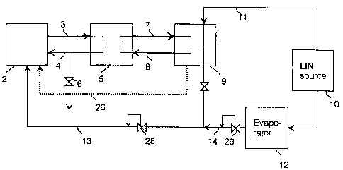
FIG. 1 is a block diagram showing an apparatus accord-
ing to the invention for maintaining a desired atmos-
phere in an essentially closed space;
FIG. 2 is a diagram showing a concentrator shown in
FIG. 1 in more detail; and
FIG. 3 is a block diagram of an alternative embodiment
of an apparatus according to the invention for main-
taining a desired atmosphere in an essentially closed
space.
DETAILED DESCRIPTION OF THE INVENTION
In the following, a first embodiment of an apparatus
and a process according to the invention for treatment
of objects in an essentially closed space will be de-
scribed with reference to Figs. 1 and 2. The objects
(not shown) that are to be treated are moved into and
through an essentially closed space 2. The space 2 is
well known in the art and comprises openings for the
obj ets to be treated, in some cases some type of gas
curtain or other device in order to minimise the amount
of oxygen entering the space through the openings etc.
The space 2 is connected to a concentrator 5 by means
of an outgoing conduit 3 and an ingoing conduit 4. An
outlet valve 6 is provided in the ingoing conduit 4,
the function of which valve will be described later.
The concentrator 5 is in turn connected to a cryo con-
densation plant (CCP) 9 through an outgoing conduit 7
and an ingoing conduit 8.
Finally, there is provided a source of liquid nitrogen
(LIN source) 10 connected to the CCP 9 through a con
CA 02349857 2001-05-04
WO 00/29798 5 PCT/SE99/02068
duit I1. The LIN source 10 is also connected to the
space 2 through an evaporator 12 and conduits 13 and
14. The conduit 13 also connects to the CCP 9.
The operation of the above-described apparatus will be
described in the following. At start-up, the 0= level
in the space 2 exceeds a desired level, e.g. 3~. In or-
der to lower the 0~ level pure nitrogen is conducted to
the space 2 from the LIN source 10 through the evapora-
tor 12 and conduits 13 and 14. Thus, the function of
the evaporator 12 is to avoid having nitrogen in liquid
form enter the space 2, which would lead to damage to
the space and objects therein.
Nitrogen is supplied from the LIN source 10 to the
space 2 until the 0= level therein is lowered to the
desired level. The objects to be treated, such as glass
bottles or video tapes, are then brought into and
through the space 2 through openings (not shown) pro-
vided therefor. Nitrogen is constantly supplied to the
space 2 in order to keep the ox_Jgen level on the de-
sired level, because new oxygen constantly leaks into
the space 2. In order to maintain the pressure in the
space 2, a flow of process gas comprising nitrogen,
solvent vapour and oxygen will then be conducted by
means of a fan (not shown) from the space 2 through the
outgoing conduit 3 and into the concentrator 5. The fan
can be provided in either conduit 3 or conduit 4.
The concentrator 5 will now be described in detail with
reference to FIG. 2. The process gas flow enters the
concentrator 5 through the conduit 3 and is brought to
one of two purifying beds 20a, 20b. There is provided a
valve 21a-d in each inlet and outlet of the beds, by
CA 02349857 2001-05-04
WO 00/29798 6 PCT/SE99/02068
which valves the bed to be used for purifying the pro-
cess gas flow is selected. The bed not used for puri-
fying the process gas flow is then shut off by means of
the valves 21a-d. If e.g. bed 20a is. to be used, valves
21a and 21b are open whereas valves 21c and 21d are
closed.
The beds 20a, 20b comprise some suitable purifying
material, such as zeolite or active carbon. When the
process gas flow is led through the beds, the solvent
vapour is separated from the process gas and is re-
tained in the purifying beds. The purified process gas
flow then leaves the concentrator via the conduit 4.
The beds 20a, 20b are also connected to the conduits 7
and 8 through valves 22a, 22b and 22c, 22d, respec-
tively. These connections are used when the beds are to
be cleaned, i.e., when they are saturated with solvent.
This cleaning process will now be described.
The conduits 7 and 8, together with the concentrator 5
and the CCP 9, form an essentially closed system for
nitrogen. A fan (not shown) is provided in the conduit
8 for the circulation of the nitrogen. There is also
provided a heater 23 in the conduit 8 for heating the
nitrogen that is about to enter the concentrator 5, see
FIG. 2. The nitrogen entering the concentrator from
conduit 8 is brought to the one of the beds 20a, 20b
that is saturated with solvent and therefore presently
not used for purifying the process gas flow from the
space 2. The selection of bed 20a, 20b is effected by
means of valves 22a-d. Thus, when bed 20a is used for
purifying the process gas flow, the nitrogen from con-
duit 8 is brought to the saturated bed 20b and vice
CA 02349857 2001-05-04
WO 00/29798 ~ PCT/SE99/02068
versa. Thus, when valve 21a is open then valve 22a must
be closed and vice versa, i.e., the two valves 21a, 22a
must not be open at the same time. However, it is pos-
sible for the two valves 21a, 22a to be closed at the
same time, e.g. when the bed 20a has been cleaned but
the other bed 20b is still functioning for purifying
the process gas flow. The same applies for the other
valve pairs 21b, 22b etc.
When the heated nitrogen enters the bed 20a or 20b from
conduit 8, the solvent in the bed is evaporated and
brought with the heated nitrogen flow leaving the con-
centrator 5 through the conduit 7 to the CCP 9. In that
way the selected bed is cleaned and can thereafter be
used to purify the incoming process gas from the space
2.
The function of the CCP 9 will now be described. It
works according to the principles of cryo condensation,
which will now be explained. In a cryo condensation
plant for condensing e.g. solvent vapour, t~~e effi-
ciency depends on the concentration of solvent in the
process gas. At higher solvent concentrations, a larger
part of the cooling effect can be used for condensation
of solvent. At lower concentration a larger part of the
cooling effect will be used for cooling nitrogen, and
this leads to a less efficient use of the cooling ca-
pacity. In other words, in order to condense the same
amount of solvent a much larger amount of LIN would be
needed for cooling in the case no concentrator was
used.
Thus, the incoming nitrogen-solvent flow from conduit 7
is cooled to a very low temperature, whereby a major
CA 02349857 2001-05-04
WO 00/29798 8 PCT/SE99/02068
part of the solvent is condensed. The cooling is effec-
ted by means of liquid nitrogen brought from the LIN
source 10 via the conduit 11. The CCP 9 then works as a
heat exchanger, wherein the liquid nitrogen from the
LIN source is evaporated thereby cooling the nitrogen-
solvent flow coming from the concentrator 5.
The condensed solvent is collected and can thereafter
be returned to the inerted space 2 and reused in the
process by means of some suitable piping means, shown
as arrow 26 in the figures. Thus, this reuse of solvent
provides an inexpensive and effective means for lower-
ing the casts for solvent.
Due to the concentrator 5, the cooling process in the
CCP 9 is a very effective one because the nitrogen-
solvent flow from the concentrator 5 contains a rela-
tively large portion of solvent.
The evaporated pure nitrogen from the LIN source 10,
after being used for cooling, is then carried to the
space 2 as a part of the nitrogen added through conduit
13.
In normal operation, when limited amounts of oxygen is
leaking into the space 2, the nitrogen used for the
cryo condensation and the amount of nitrogen needed for
inerting the space 2 is essentially balanced, i.e., all
nitrogen used for cooling the CCP goes directly onward
to the inerted space 2 and small amounts of or no ni-
trogen has to be used in the CCP that can not be used
in the inerted space 2. This means that there is no
additional cost for the cryo condensation process in
the CCP 9. In effect, in addition to working as a con-
CA 02349857 2001-05-04
WO 00/29798 9 PCT/SE99/02068
denser, the CCP 9 also functions as an evaporator, fur-
ther increasing the cost-efficiency of the inventive
method and apparatus.
A second embodiment of the invention will now be de-
scribed with reference to FIG. 3. The only change from
the embodiment described with reference to Figs. 1 and
2 lies in the CCP 9. In the first embodiment, this
functioned as a heat exchanger with two separate sys-
tems, viz. the system connected to the concentrator 5
with the function to condense the solvent and the sys-
tem connected to the LIN source 10 with the function to
cool the nitrogen carrying the solvent, respectively.
In this second embodiment, the CCP works in a different
way.
As seen in FIG. 3, the CCP 9 is still connected to the
LIN source 10 and the liquid nitrogen supplied through
conduit 11 is used for cooling. However, instead of be-
ing carried to the space 2, the then evaporated nitro-
gen used for cooling is supplied to the concentrator 5
through the conduit 8. This nitrogen is heated by
heater 23, see FIG. 2, before being brought to one of
the beds 20a, 20b to be cleaned, just as in the first
embodiment. In this second embodiment, however, the fan
(not shown) used for circulating the nitrogen in con-
duit 8 can be omitted, as the pressure from the LIN
source 10 is sufficient for forcing the nitrogen
through the system.
After leaving the concentrator 5, the nitrogen used for
cleaning the beds is carried through conduit 7 to the
CCP 9, wherein the solvent is condensed. Thereafter,
the nitrogen, now with only a minor part of solvent, is
CA 02349857 2001-05-04
WO 00/29798 10 PCT/SE99/02068
lead to the space 2 for inertion. Thus, the system CCP
9, concentrator 5 and conduits 7, 8 no longer forms a
closed system for nitrogen.
This second embodiment provides several advantages.
Firstly, the fan in conduit 8 can be omitted, thus sav-
ing costs. Secondly, the nitrogen supplied through this
conduit 8 is pure, i.e., it contains essentially no
oxygen as it comes essentially directly from the LIN
source 10. This eliminates the hazards connected to the
heater 23 as already small amounts of oxygen in contact
therewith can cause an explosion.
The self-regulating system of inerting nitrogen coming
from the CCP 9 and the evaporator 12 will now be de-
scribed with reference to FIG. 1. As is seen in that
figure, there are provided two pressure controllers 28,
29 in conduit 13 and in the conduit 14 leaving the
evaporator 12, respectively. The set pressure value of
controller 28 is slightly higher than that of control-
ler 29, e.g. 200 mbar and 190 mbar, respectively. The
nitrogen in conduit 13 then comes primarily from the
CCP 9 and only in case there is not sufficient nitrogen
supply therefrom, i.e., the pressure drops in conduit
13 before pressure controller 28, nitrogen will be sup-
plied from the evaporator 12 and conduit 14. In that
way it is ensured, that the nitrogen used for cooling
the CCP 9 also will be used for inerting the space 2
and that nitrogen coming from the LIN source 10 through
the evaporator 12 will be used only in case the nitro-
gen used for cooling is not sufficient for inerting the
space 2. Thus, this provides a very cost-efficient way
of reducing the amount of LIN used.
CA 02349857 2001-05-04
WO 00/29798 11 PCT/SE99/02068
The function of the valve 6 will now be described with
reference to FIG. 1. A fundamental feature of the pro-
cess is that oxygen leaks into the space and an in-
erting gas, e.g. nitrogen, must therefore be supplied
to the space 2. Oxygen and nitrogen together with sol-
vent vapour is carried as a process gas flow from the
space 2 to the concentrator 5. The nitrogen together
with oxygen is then returned to the space 2 through
conduit 4. In case all the nitrogen-oxygen mixture is
returned, this would cause an excess pressure in the
space 2. Therefore, some of this nitrogen-oxygen mix-
ture is bled off through valve 6 and into the surround-
ing environment. This has been made feasible due to the
fact that this nitrogen-oxygen mixture is essentially
free of solvent vapour and thus does not constitute an
environmental hazard.
By using the method and the apparatus according to the
invention, the consumption of LIN can be substantially
reduced. It has been experimentally shown, that the LIN
consumption can be lowered by a factor 8-10. The number
of times the nitrogen can be reused depends on how much
oxygen is leaking into the space 2. In addition, the
condensed solvent can be brought back to the process,
whereby the amount of added solvent can be reduced. The
LIN used for reducing the level of oxygen can be used
not only for that but also to condense the solvent af-
ter the concentrator.
Often when using solely cryogen condensation the re-
quirements on VOC discharge can not be fulfilled. With
the method and the apparatus according to the inven-
tion, wherein also a concentrator is used, the VOC dis-
charge can be kept on a low level complying with the
CA 02349857 2001-05-04
WO 00/29798 12 PC'T/SE99/02068
requirements also in countries with very strict rules
regarding VOC discharge.
In view of the foregoing description it will be evident
to a person skilled in the art that various modifica-
tions may be made within the scope of the claims. For
example, although two cleaning beds have been shown,
any number of beds can be used. If only one bed is
used, the process is run intermittently, i.e., the pro-
cess is run until the bed is saturated with solvent and
then the inerting process is shut down and the process
cleaning the bed is initiated.
Also, the inventive method and apparatus are not lim-
ited to VOC, such as solvents, but is also applicable
to other types of condensable substances, such as
hydrocarbons.