Language selection

Search

Patent 2350287 Summary

Third-party information liability

Some of the information on this Web page has been provided by external sources. The Government of Canada is not responsible for the accuracy, reliability or currency of the information supplied by external sources. Users wishing to rely upon this information should consult directly with the source of the information. Content provided by external sources is not subject to official languages, privacy and accessibility requirements.

Claims and Abstract availability

Any discrepancies in the text and image of the Claims and Abstract are due to differing posting times. Text of the Claims and Abstract are posted:

  • At the time the application is open to public inspection;
  • At the time of issue of the patent (grant).
(12) Patent Application: (11) CA 2350287
(54) English Title: HOLDING FURNACE PARTICULARLY FOR VACUUM DIE-CASTING APPARATUS
(54) French Title: FOUR D'ATTENTE PARTICULIEREMENT ADAPTE POUR LES APPAREILS DE COULEE SOUS VIDE
Status: Deemed Abandoned and Beyond the Period of Reinstatement - Pending Response to Notice of Disregarded Communication
Bibliographic Data
(51) International Patent Classification (IPC):
  • B22D 18/06 (2006.01)
  • B22D 2/00 (2006.01)
  • B22D 17/28 (2006.01)
  • B22D 17/30 (2006.01)
  • B22D 17/32 (2006.01)
  • B22D 21/02 (2006.01)
  • B22D 39/00 (2006.01)
  • C21B 3/10 (2006.01)
  • C22B 9/00 (2006.01)
  • F27B 14/04 (2006.01)
  • F27B 14/08 (2006.01)
  • F27B 14/12 (2006.01)
  • F27D 1/18 (2006.01)
  • F27D 21/00 (2006.01)
  • F27D 27/00 (2010.01)
(72) Inventors :
  • MORTARI, GRAZIANO (Italy)
(73) Owners :
  • IDRA PRESSE S.P.A.
(71) Applicants :
  • IDRA PRESSE S.P.A. (Italy)
(74) Agent: NORTON ROSE FULBRIGHT CANADA LLP/S.E.N.C.R.L., S.R.L.
(74) Associate agent:
(45) Issued:
(22) Filed Date: 2001-06-12
(41) Open to Public Inspection: 2001-12-20
Availability of licence: N/A
Dedicated to the Public: N/A
(25) Language of filing: English

Patent Cooperation Treaty (PCT): No

(30) Application Priority Data:
Application No. Country/Territory Date
PD2000U000046 (Italy) 2000-06-20

Abstracts

English Abstract


A holding furnace, particularly for a die-casting apparatus, comprising a
bucket which can be heated, is adapted to contain molten material and is
provided with a lid which can be opened and is shaped substantially like an
inverted cup; the lid is provided with at least one opening for introducing
protective gas having a higher relative density than air and adapted to
generate an atmosphere for protection from contact with air for the molten
material at regions that are free from the containment means walls of the
bucket.


Claims

Note: Claims are shown in the official language in which they were submitted.

6
THE EMBODIMENTS OF THE INVENTION IN WHICH AN EXCLUSIVE
PROPERTY OR PRIVILEGES IS CLAIMED ARE DEFINED AS FOLLOWS:
1. A holding furnace, particularly for a die-casting apparatus, comprising
a bucket which can be heated, is adapted to contain molten material and is
provided with a lid which can be opened and is shaped substantially like an
inverted cup, said lid being provided with at least one opening for
introducing a protective gas having a higher relative density than air and
adapted to generate an atmosphere for protection from contact with air for
said molten material at regions that are free from the containment walls of
the bucket.
2. The furnace according to claim 1, wherein said lid is provided with at
least one probe for detecting at least one physical characteristic of the
protective gas.
3. The furnace according to claim 2, wherein said at least one physical
characteristic to be detected is the temperature of the protective gas.
4. The furnace according to claim 1, wherein said protective gas is
nitrogen.

Description

Note: Descriptions are shown in the official language in which they were submitted.


CA 02350287 2001-06-12
1
The present invention relates to a holding furnace particularly for a die-
casting apparatus.
s In the die-casting process, the main step consists in injecting a specific
amount of molten metallic material in a die; optionally, in the case of
vacuum die-casting; this is done after producing a vacuum inside the die.
In terms of plant maintenance and amortization costs, the die-casting
process is highly advantageous if it relates to the production of large
batches
io meant for high-volume mass-manufacturing lines.
The recent trend is to use light alloys to produce castings to be used as
structural elements and/or components, such as for example car chassis and
body parts of assembly-line vehicles.
Standard die-casting apparatuses, however, are scarcely suited for the
is production of vehicle frame or body components due to their brittle
fracture
behavior and to the porosity of the resulting castings.
It is in fact currently impossible to produce Al-Mg alloy castings,
because such castings are full of porosities, with a high number of
inclusions of gas and impurities.
ao Brittle fracture, porosity and inclusions are unacceptable in castings
which should be welded and which are required, in various forms, to have
high plastic deformation properties.
The main causes of the above mentioned problems are the very structure
and geometry of the parts that constitute standard die-casting apparatuses.
Zs Before injection into the die, tl~e molten material is retained in a
holding
furnace.
The holding furnaces currently in use are substantially constituted by
containment bowls in which the molten material is kept at a constant
temperature.
3o However, the material contained in the furnace is in contact with

CA 02350287 2001-06-12
' 2
contaminating atmospheres constituted for example by air, consequently
generating oxides and forming inclusions of gas inside the casting.
Moreover, slag is sometimes present on the containment walls of the
furnace and may compromise the purity of the casting and therefore its final
s mechanical characteristics.
The aim of the present invention is to provide a holding furnace whose
structure is such as to solve the above noted problems observed in
conventional holding furnaces.
to Within this aim, an object of the present invention is to provide a
furnace having such a structure that the molten material never makes contact
with contaminating atmospheres or slag.
Another object of the invention is to provide a furnace which allows to
work in a protective gas atmosphere.
is Another object of the invention is to provide a holding furnace having a
particularly simple structure.
This aim and these and other objects and others which will become better
apparent hereinafter are achieved by a holding furnace, particularly for a
die-casting apparatus, characterized in that it comprises a bucket which can
ao be heated, is adapted to contain molten material and is provided with a lid
which can be opened and is shaped substantially like an inverted cup, said
lid being provided with at least one opening for introducing a protective gas
having a higher relative density than air and adapted to generate an
atmosphere for protection from contact with air for said molten material at
2s regions that are free from the containment means of the bucket.
Further characteristics and advantages of the present invention will
become better apparent from the following detailed description of a
preferred but not exclusive embodiment thereof, illustrated only by way of
3o non-limitative example in the accompanying drawings, wherein:

CA 02350287 2001-06-12
3
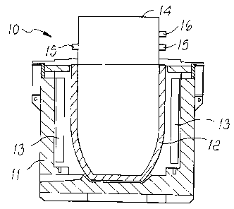
Figure 1 is a sectional view of a furnace according to the present
invention;
Figure 2 is a plan view of a portion of a die-casting apparatus in which a
furnace having the structure according to the invention is used.
s
With reference to the figures, a holding furnace according to the
invention is generally designated by the reference numeral 10.
The furnace 10 is constituted by a substantially hollow body 11 which
contains a bucket 12 for containing molten metallic material.
io Heating elements 13 are provided on internal walls of the body 11 and
are adapted to maintain the temperature of the molten material contained in
the bucket 12.
The containment bucket 12 is provided with a lid 14 which is
substantially shaped like an inverted cup and in which a protective gas,
is advantageously nitrogen, is contained which is adapted to generate an
atmosphere for continuous protection against contact with air for the
material contained in the bucket 12, at the surface that is not affected by
the
containment walls of the bucket 12.
Since nitrogen is a gas which is heavier than air, the danger of contact
Zo between air and molten material, and therefore the generation of oxides
which generate inclusions, is eliminated both when the lid 14 is closed and
when it is open.
The lid 14 is provided with openings 15 for introducing the protective
gas and with openings for placing probes 16 which are adapted to detect the
Zs physical characteristics of the gas..
In this case, the probe 16 is a thermocouple which detects the
temperature of the gas.
The bucket 12 further has rounded walls which follow the revolving
motion of a mixer 17 which allows to clean and degas the molten material.
3o Moreover, the rounded walls facilitate the cleaning of any slag by virtue

CA 02350287 2001-06-12
' 4
of corresponding cleaning means, which are not shown in the figure but are
in any case of a per se known type.
The lid 14 can of course be opened to allow the insertion of the mixer 17
and the loading of the molten material.
s In a die-casting apparatus it is possible to use two holding furnaces 10a
and 10b mounted on a turntable 18.
The turntable 18 is circular and the two furnaces 10a and 10b are
mounted in diametrically opposite positions.
Means for moving the turntable are associated with the turntable 18 and
to also comprise a motor 19.
In a region below the turntable 18, at the floor, there is a duct 20 in
which protective gas flows; the gas arrives from a station, not shown in the
figure, and flows toward the inlets 15a and 15b of the corresponding
holding furnaces 10a and 10b.
is When the furnace 10b is located at the mixer 17, the corresponding lid
14b opens to allow the insertion of the mixer 17 and the loading of the
material by means of the loading channel 21.
The mixer 17 is then removed from the furnace 10b, the lid 14b is closed,
and the turntable 18 turns until the furnace 18b is in the position that is
ao occupied in Figure 2 by the furnace 10a, from which the molten material is
taken in order to be loaded into injection units, not shown, of the die-
casting
apparatus.
At this point, it is the furnace l0a that is subjected to the cleaning and
degassing operation by means of the mixer 17 and to loading with new
2s molten material.
In practice it has been observed that the present invention has achieved
the intended aim and objects.
A holding furnace has been in fact provided which allows to keep
constantly in contact with a protective gas atmosphere the regions that are
3o not affected by the means for containing the molten material.

CA 02350287 2001-06-12
' S
Accordingly, one of the main problems of using light alloys, such as Al-
Mg alloys, in standard and innovative die-casting apparatuses is eliminated
if a holding furnace having the structure according to the invention is used.
The technical details may be replaced with other technically equivalent
s elements.
The materials, so long as they are compatible with the contingent use, as
well as the dimensions, may be any according to requirements.

Representative Drawing
A single figure which represents the drawing illustrating the invention.
Administrative Status

2024-08-01:As part of the Next Generation Patents (NGP) transition, the Canadian Patents Database (CPD) now contains a more detailed Event History, which replicates the Event Log of our new back-office solution.

Please note that "Inactive:" events refers to events no longer in use in our new back-office solution.

For a clearer understanding of the status of the application/patent presented on this page, the site Disclaimer , as well as the definitions for Patent , Event History , Maintenance Fee  and Payment History  should be consulted.

Event History

Description Date
Inactive: IPC deactivated 2011-07-29
Inactive: IPC from MCD 2010-02-01
Inactive: IPC expired 2010-01-01
Application Not Reinstated by Deadline 2007-06-12
Time Limit for Reversal Expired 2007-06-12
Deemed Abandoned - Failure to Respond to Maintenance Fee Notice 2006-06-12
Inactive: Abandon-RFE+Late fee unpaid-Correspondence sent 2006-06-12
Inactive: IPC from MCD 2006-03-12
Application Published (Open to Public Inspection) 2001-12-20
Inactive: Cover page published 2001-12-19
Inactive: IPC assigned 2001-08-13
Inactive: First IPC assigned 2001-08-13
Letter Sent 2001-07-12
Application Received - Regular National 2001-07-12
Filing Requirements Determined Compliant 2001-07-12
Inactive: Filing certificate - No RFE (English) 2001-07-12

Abandonment History

Abandonment Date Reason Reinstatement Date
2006-06-12

Maintenance Fee

The last payment was received on 2005-06-13

Note : If the full payment has not been received on or before the date indicated, a further fee may be required which may be one of the following

  • the reinstatement fee;
  • the late payment fee; or
  • additional fee to reverse deemed expiry.

Please refer to the CIPO Patent Fees web page to see all current fee amounts.

Fee History

Fee Type Anniversary Year Due Date Paid Date
Application fee - standard 2001-06-12
Registration of a document 2001-06-12
MF (application, 2nd anniv.) - standard 02 2003-06-12 2003-06-12
MF (application, 3rd anniv.) - standard 03 2004-06-14 2004-06-09
MF (application, 4th anniv.) - standard 04 2005-06-13 2005-06-13
Owners on Record

Note: Records showing the ownership history in alphabetical order.

Current Owners on Record
IDRA PRESSE S.P.A.
Past Owners on Record
GRAZIANO MORTARI
Past Owners that do not appear in the "Owners on Record" listing will appear in other documentation within the application.
Documents

To view selected files, please enter reCAPTCHA code :


To view images, click a link in the Document Description column. To download the documents, select one or more checkboxes in the first column and then click the "Download Selected in PDF format (Zip Archive)" or the "Download Selected as Single PDF" button.

List of published and non-published patent-specific documents on the CPD .

If you have any difficulty accessing content, you can call the Client Service Centre at 1-866-997-1936 or send them an e-mail at CIPO Client Service Centre.


Document
Description 
Date
(yyyy-mm-dd) 
Number of pages   Size of Image (KB) 
Representative drawing 2001-11-22 1 10
Description 2001-06-12 5 223
Abstract 2001-06-12 1 22
Claims 2001-06-12 1 34
Drawings 2001-06-12 1 28
Cover Page 2001-12-14 1 38
Courtesy - Certificate of registration (related document(s)) 2001-07-12 1 112
Filing Certificate (English) 2001-07-12 1 163
Reminder of maintenance fee due 2003-02-13 1 106
Reminder - Request for Examination 2006-02-14 1 117
Courtesy - Abandonment Letter (Request for Examination) 2006-08-21 1 167
Courtesy - Abandonment Letter (Maintenance Fee) 2006-08-07 1 175