Language selection

Search

Patent 2350452 Summary

Third-party information liability

Some of the information on this Web page has been provided by external sources. The Government of Canada is not responsible for the accuracy, reliability or currency of the information supplied by external sources. Users wishing to rely upon this information should consult directly with the source of the information. Content provided by external sources is not subject to official languages, privacy and accessibility requirements.

Claims and Abstract availability

Any discrepancies in the text and image of the Claims and Abstract are due to differing posting times. Text of the Claims and Abstract are posted:

  • At the time the application is open to public inspection;
  • At the time of issue of the patent (grant).
(12) Patent Application: (11) CA 2350452
(54) English Title: FIXING DEVICE FOR A PANE OF GLASS
(54) French Title: DISPOSITIF DE FIXATION POUR VITRE
Status: Deemed Abandoned and Beyond the Period of Reinstatement - Pending Response to Notice of Disregarded Communication
Bibliographic Data
(51) International Patent Classification (IPC):
  • E06B 3/54 (2006.01)
  • E04F 13/08 (2006.01)
(72) Inventors :
  • ELMER, HUBERT (Austria)
(73) Owners :
  • DORMA GMBH + CO. KG
(71) Applicants :
  • DORMA GMBH + CO. KG (Germany)
(74) Agent: SMART & BIGGAR LP
(74) Associate agent:
(45) Issued:
(86) PCT Filing Date: 2000-09-19
(87) Open to Public Inspection: 2001-03-29
Availability of licence: N/A
Dedicated to the Public: N/A
(25) Language of filing: English

Patent Cooperation Treaty (PCT): Yes
(86) PCT Filing Number: PCT/EP2000/009164
(87) International Publication Number: WO 2001021922
(85) National Entry: 2001-05-11

(30) Application Priority Data:
Application No. Country/Territory Date
199 45 196.6 (Germany) 1999-09-21

Abstracts

English Abstract


The invention relates to a fixing device (1) for fixing a pane of glass (2) on
a wall (3), on a substructure located on or in a building, or similar, whereby
the fixing unit (5) which supports the glass pane (2) is supported with
limited articulation on a clamping fitting (4). The invention is characterised
in that the fixing unit (5) has a retaining pin (6) which can be mounted in a
fixed manner on the clamping fitting (4) and whose free external end (7) is
connected to a compensation shaft (9) via a joint (8) which can be fixed in
position. The compensation shaft, in turn, is connected to an adapter which
can be attached to a wall (3) or similar, via a joint (11) which can be fixed
in position.


French Abstract

La présente invention concerne un dispositif de fixation (1) servant à fixer une vitre (2) à une paroi (3) dans une sous-construction de la partie latérale d'un bâtiment ou analogue. L'élément de support (5) soutenant la vitre (2) est supporté de manière légèrement articulée dans l'espace au niveau d'une armature de serrage (4). L'invention se caractérise en ce que l'élément de support (5) présente une tige de retenue (6) pouvant être fixée à l'armature de serrage (4), dont l'extrémité externe libre (7) est reliée à un axe de compensation (9) via une articulation (8) pouvant être immobilisée, ledit axe étant lui-même relié à un adaptateur pouvant être connecté à une paroi (3) ou analogue, via une articulation (11) pouvant être immobilisée.

Claims

Note: Claims are shown in the official language in which they were submitted.

6
Claims
1. Fastening device for a glass panel (2) on a wall (3), a
building-side substructure or similar object using a
clamp fitting (4) that grips the glass panel (2) and a
holder (5) that is supported on the clamp fitting (4)
so that it can move to a limited extent in three
dimensions, characterized by the fact that the holder
(5) has a retaining pivot (6) that can be fixed in
position on the clamp fitting (4), whereby on the outer
free end (7) of the retaining pivot there is a
connecting articulation (8) that can be fixed in
position for the connection of a compensating shaft
(9), which on its end (10) farther from the retaining
pivot (6) is connected by means of an articulation (11)
that can be fixed in position with an adapter (12) for
fastening to a wall (3), a substructure or similar
object.
2. Fastening device as claimed in Claim 1, characterized
by the fact that a pivot fork (13) is realized on the
outer free end (7) of the retaining pivot (6).
3. Fastening device as claimed in Claims 1 and 2,
characterized by the fact that pivot brackets (15) are
located on the opposite free ends (10, 14) of the
compensating shaft (9).
4. Fastening device as claimed in one of the Claims 1 to
3, characterized by the fact that the adapter (12) has
a pivot fork (16).
5. Fastening device as claimed in one of the Claims 1 to
4, characterized by the fact that the pivot forks (13,
16) of the retaining pivot (6) and of the adapter (12)
and the pivot brackets (15) of the compensating shaft

7
(9) have aligned borings (17) to receive a clamp screw
(18).
6. Fastening device as claimed in one of the Claims 1 to
5, characterized by the fact that the retaining pivot
(6) can be fixed in position on the clamp fitting (4)
by means of a cap nut (20) that covers or fits over a
cap bell (19) of the clamp fitting (4).
7. Fastening device as claimed in Claim 6, characterized
by the fact that the cap nut (20) has a flat (22) on
its shell surface (21) for the application of a wrench.
8. Fastening device as claimed in one of the Claims 1 to
7, characterized by the fact that the compensating
shaft (9) has a flat (24) on its shell surface (23) for
the application of a wrench.
9. Fastening device as claimed in one of the Claims 1 to
8, characterized by the fact that the pivot brackets
(15) are rotationally mounted in the compensating shaft
(9).

Description

Note: Descriptions are shown in the official language in which they were submitted.


CA 02350452 2001-05-11
WO 01/21922 PCT/EP00/09164
1
Title: Fixing device for a pane of glass
Description
This invention relates to a fastening device for fastening a
glass panel to a wall, a building-side substructure or
similar object using a clamp fitting that grips the glass
panel and a holder that is supported on the clamp fitting so
that it can swivel to a limited extent in three dimensions.
On fastening devices of the type described above, it is
necessary on one hand to realize the clamp fitting or
punctiform holder that grips the glass panel itself so that
the stresses that are introduced into the glass panel can be
neutralized to the greatest extent possible in the vicinity
of the clamp fitting itself. On the other hand, it is also
necessary to realize the holder that is adjacent to the
clamp fitting so that a stress-free connection of the clamp
fitting and thus of the glass panel to a building-side
substructure, a wall or another glass panel is possible. In
particular for a connection to a substructure or wall, it
should thereby be possible to compensate for rather large
construction tolerances in the form of an appropriate
adaptation capability of the holder.
As disclosed in an older application by the same applicant
(Case No. 199 15 193.8) that is not yet part of the prior
art, the holder is supported in the clamp fitting so that it
can move to a limited extent in three dimensions, whereby a
cap bell is supported with adjustable bias on the inside
clamp element, and between the cap bell and the inside clamp
element there is a permanently elastic spring element that
permits a relative movement of the cap bell with respect to
the clamp element.

CA 02350452 2001-05-11
WO 01/21922 PCT/EP00/09164
2
The object of the invention is to realize the fastening
device so that the stress-free gripping of the glass panel
by the associated mounting makes it possible to adjust to
rather large construction tolerances of a wall, a
substructure or similar object.
The invention teaches that the object described above can be
accomplished by means of the features disclosed in Claim 1.
Claim l teaches that the holder has a retaining pivot that
can be fastened to a clamp fitting, whereby on the outer
free end of the retaining pivot there is a connecting joint
that can be fixed in position for the connection of a
compensating shaft, which on its end that is farther from
the connecting bridge is connected by means of a respective
joint that can be fixed :in position with an adapter for
fastening to a wall, a substructure or similar object.
The invention therefore teaches that two articulations,
joints, or hinges are located between the glass panel and
the substructure, so that during installation a correct
adaptation of the adapter that forms the connection to the
substructure or wall is guaranteed. After the two
articulations have been fixed in position - apart from the
limited three-dimensional movement that is still possible in
the vicinity of the clamp fitting - the result is a rigid
fastening unit.
~5 Additional characteristics of the invention are disclosed in
the dependent claims.
In one advantageous embodiment of the invention, pivot forks
are located on the respective free ends of the retaining
pivot and of the adapter, which pivot forks are connected
with corresponding pivot brackets on the opposite free ends
of the compensating shaft to form an articulation, joint, or
hinge that can be fixed in position. It goes without saying

CA 02350452 2001-05-11
WO 01/21922 PCT/EP00/09164
3
that in a kinematic reversal, pivot forks can also be
provided on the compensating shaft.
To fix the above mentioned articulations in position, the
pivot forks of the retaining shaft and the pivot brackets of
the compensating shaft have aligned borings to receive clamp
screws.
As mentioned above, the holder is supported on the clamp
fitting that grips the glass panel so that the holder can
move to a limited extent in three dimensions. The invention
teaches that this capability is realized because the
retaining pivot can be fixed in position on the clamp
fitting by means of a cap nut that covers or fits over a cap
bell of the clamp fitting.
On one hand to facilitate the adjustment or adaptation of
the holder, in particular of the adapter, during the
installation on the wall or similar structure, and on the
other hand to guarantee the individual connections,
including the fixing of the retaining pivot in position by
the cap nut, the cap nut and the compensating shaft have
flats on their shell surfaces for the application of a
wrench.
In an additional embodiment of the invention, the pivot
brackets are mounted so that they can rotate in the
compensating shaft.
The invention is explained in greater detail below with
reference to the exemplary embodiment illustrated into the
accompanying figures, in which:
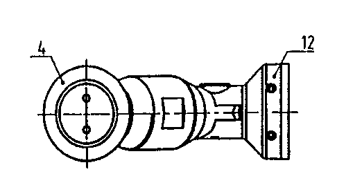
Figure 1: is an exploded view in perspective of the
fastening device.
Figure 2: is a head-on view.

CA 02350452 2001-05-11
WO 01/21922 PCT/EP00/09164
4
Figure 3: is an overhead view of the embodiment illustrated
in Figure 2.
With reference to Figure 1, a fastening device 1 consists
essentially of three components, namely a clamp fitting 4, a
compensating shaft 9 and an adapter 12, whereby between
these two components two articulations 8 and 11 (See Figure
3) that can be fixed in position are formed. The overall
holder is designated 5.
A glass panel 2 is gripped by means of the clamp fitting 4.
A retaining pivot 6 is held in the clamp fitting 4 between a
cap bell 19 and a cap nut 20 of the clamp fitting 4. A free
end 7 of the retaining pivot 6 is realized in the form of a
pivot fork 13. The same is true for the adapter 12, which
also has a pivot fork 16. The compensating shaft 9, on its
free ends 10 and 14, has pivot brackets 15 which are
received, held, or contained by the pivot forks 13, 16.
Aligned borings 17 run through both the pivot brackets 15
and the pivot forks 13, 16. The articulations 8 and 11 can
be rigidly fixed in position by means of clamp screws 18
that run through these aligned borings 17.
The accompanying figures also show that a shell surface 21
of the cap nut 20 has a flat 22 for the application of a
wrench. The same is true of a shell surface 23 of the
compensating shaft 9. The corresponding flat is designated
24.
For the adjustment to a wall 3, for example, the adapter 12
consists of two components that can be rotated with respect
to each other, and can be fixed in position with respect to
each other by means of Allen screws 25.

CA 02350452 2001-05-11
WO 01/21922 PCT/EP00/09164
Nomenclature
1 Fastening device
2 Glass panel
3 Wall
5 4 Clamp fitting
5 Holder
6 Retaining pivot
7 Free end of the retaining pivot
8 Connecting articulation that can be fixed in position
9 Compensating shaft
10 End of the compensating shaft
11 Articulation that can be fixed in position
12 Adapter
13 Pivot fork
14 End of the compensating shaft
15 Pivot bracket
16 Pivot fork
17 Borings
18 Clamp screw
19 Cap bell
20 Cap nut
21 Shell surface
22 Flat
23 Shell surface
24 Flat
25 Allen screw

Representative Drawing
A single figure which represents the drawing illustrating the invention.
Administrative Status

2024-08-01:As part of the Next Generation Patents (NGP) transition, the Canadian Patents Database (CPD) now contains a more detailed Event History, which replicates the Event Log of our new back-office solution.

Please note that "Inactive:" events refers to events no longer in use in our new back-office solution.

For a clearer understanding of the status of the application/patent presented on this page, the site Disclaimer , as well as the definitions for Patent , Event History , Maintenance Fee  and Payment History  should be consulted.

Event History

Description Date
Application Not Reinstated by Deadline 2005-09-19
Time Limit for Reversal Expired 2005-09-19
Deemed Abandoned - Failure to Respond to Maintenance Fee Notice 2004-09-20
Inactive: Cover page published 2001-09-19
Letter Sent 2001-09-13
Inactive: Correspondence - Transfer 2001-08-21
Inactive: First IPC assigned 2001-08-14
Inactive: Courtesy letter - Evidence 2001-07-31
Inactive: Notice - National entry - No RFE 2001-07-25
Application Received - PCT 2001-07-13
Inactive: Single transfer 2001-06-18
Application Published (Open to Public Inspection) 2001-03-29

Abandonment History

Abandonment Date Reason Reinstatement Date
2004-09-20

Maintenance Fee

The last payment was received on 2003-08-13

Note : If the full payment has not been received on or before the date indicated, a further fee may be required which may be one of the following

  • the reinstatement fee;
  • the late payment fee; or
  • additional fee to reverse deemed expiry.

Please refer to the CIPO Patent Fees web page to see all current fee amounts.

Fee History

Fee Type Anniversary Year Due Date Paid Date
Basic national fee - standard 2001-05-11
Registration of a document 2001-06-18
MF (application, 2nd anniv.) - standard 02 2002-09-19 2002-09-04
MF (application, 3rd anniv.) - standard 03 2003-09-19 2003-08-13
Owners on Record

Note: Records showing the ownership history in alphabetical order.

Current Owners on Record
DORMA GMBH + CO. KG
Past Owners on Record
HUBERT ELMER
Past Owners that do not appear in the "Owners on Record" listing will appear in other documentation within the application.
Documents

To view selected files, please enter reCAPTCHA code :


To view images, click a link in the Document Description column. To download the documents, select one or more checkboxes in the first column and then click the "Download Selected in PDF format (Zip Archive)" or the "Download Selected as Single PDF" button.

List of published and non-published patent-specific documents on the CPD .

If you have any difficulty accessing content, you can call the Client Service Centre at 1-866-997-1936 or send them an e-mail at CIPO Client Service Centre.


Document
Description 
Date
(yyyy-mm-dd) 
Number of pages   Size of Image (KB) 
Representative drawing 2001-08-27 1 6
Abstract 2001-05-11 1 70
Description 2001-05-11 5 193
Claims 2001-05-11 2 66
Drawings 2001-05-11 1 24
Cover Page 2001-09-18 1 37
Notice of National Entry 2001-07-25 1 194
Courtesy - Certificate of registration (related document(s)) 2001-09-13 1 136
Reminder of maintenance fee due 2002-05-22 1 111
Courtesy - Abandonment Letter (Maintenance Fee) 2004-11-15 1 176
Reminder - Request for Examination 2005-05-24 1 116
Correspondence 2001-07-25 1 24
PCT 2001-05-11 3 110
Fees 2002-09-04 1 35