Note: Descriptions are shown in the official language in which they were submitted.
CA 02350460 2001-05-10
WO 00/28144 PCT/US99/26830
COMPOSITE RAILROAD CROSSTIE
The subject invention relates to a railroad cross tie and a method of making
the same.
Railroad crossties have been made almost exclusively of wood from the
beginning of
the railroad age. The wooden crossties are held in place by ballast rock, and
the rails are
attached using tie plates and cut spikes. This is a readily available and
commonly used
system. The wooden ties accept and hold spikes, so that the rail and tie plate
fastening
systems may be secured to the ties. A wood tie will flex under load. The
resulting flexing is
beneficial only in that it helps to provide for.a softer ride. However, the
flexing also increases
the displacement of, or "pumping" of, the supporting ballast out and away from
the tie. This
increases maintenance cost. The flexing also "pumps" or works the spikes up
and loosens
them, resulting in additional maintenance cost. Wooden ties deteriorate and
must be replaced
at regular intervals, resulting in further maintenance costs.
Railroad ties made of material other than wood have been proposed. For
example,
U.S. Patent No. 5,238,734 to Murray discloses a railroad tie made from a
mixture of recycled
tire fragments and an epoxy mixture. Other patents disclosing railroad ties
made out of
composite materials include U.S. Patent No. 4,150,790 (Potter) and U.S. Patent
No.
4,083,491 (Hill). Although ties made out of composite materials provide
significantly longer
life than conventional wooden ties, it has not been possible to provide
composite ties that are
durable enough to withstand the heavy repeated loads of main line railroad
tracks. Both
wooden and composite railroad ties tend to pump ballast rock away from the
rails, thus
requiring frequent reballasting.
Concrete crossties that are reinforced with various materials are also known
in the
prior art, such as the crosstie disclosed in U.S. Patent No. 1,566,550
(McWilliam). However,
conventional concrete crossties are too hard and brittle to use conventional
and standard
fastening systems (tie plates and cut spikes). Concrete ties use pre-casted
fasteners that are
attached during the curing stage in the tie manufacturing process.
Furthermore, each tie must
be individually loaded and obstructed from the mold. At first glance, it would
appear that the
concrete crossties, since they are stiff and non-flexible, would be
advantageous and provide a
stiffer track module, improved lateral stability and gauge control, increased
rail life, and
greater locomotive fuel economy. However, what appeared to have been a
significantly lower
maintenance cost due to the lack of "pumping" of the ballast rock, has
actually become
CA 02350460 2001-05-10
WO 00/28144 PCT/US99/26830
2
another maintenance cost. The concrete tie is so hard that it pulverizes the
ballast rock
beneath it which results in a sand like or soft support system.
The railroad crosstie according to the present invention combines the best
features of
the wooden and concrete crossties. The present invention offers all the
benefits of the
concrete tie while adding "shock absorbing" and "impact resistance" features
with the outer
composite shell. This helps to eliminate the pulverizing of the ballast rock.
The ballast rock
actually imbeds itself into the composite helping to keep it in place.
Accordingly, an outer casing is provided which is made out of, preferably, a
50/50
mixture of high density polyethylene (such as from recycled household
containers) in which
reinforcing beams have been mounted in the cavity within the casing. The new
system also
uses traditional fastening systems. Inserts are placed within the beams that
are made out of
the same composite material from which the casing is made, and the upper
surfaces of the
beams define apertures so that spikes can be driven through the casings, the
apertures, and
into the inserts. The rubber and plastic mixture is sufficiently yieldable so
that spikes can be
driven through the casing and into the inserts in much the same way as spikes
can be driven in
conventional wooden crossties. The rubber gives the composite a "gripping
feature" that has
been proven to hold the spike better than wood, resulting in higher spike pull
testing. The
cavity is then filled with concrete, including the portions of the cavity
within the beams and
between the inserts. The beams, which are preferably made of steel, stiffen
the cross tie and
prevent pulverizing of the concrete. If heavier axle loads are to be
accommodated, tubular
beams made out of a heavier gauge of steel may be used, which stiffens the
beam, resulting in
a higher positive bending moment. The higher the bending moment the better the
track
modules.
Accordingly, crossties made according to the present invention have a bending
moment that can be manipulated to best fit the end user's needs while having a
cross section
of the standard 7" x 9" size; any concrete tie which meets the railroads
requirements must be
8" x 10" in cross section. Any tie other than a 7" x 9", can not be used as a
replacement tie
for the 14,000,000 ties that are replaced each year. The ability to adjust the
bending moment
and remain within the 7" x 9" cross section is highly advantageous and unique
to this
invention.
CA 02350460 2005-06-23
3
Accordingly, a railroad crosstie is provided that combines the benefits of
conventional
wooden ties and concrete ties. The cross tie has the durability and load
carrying capacity of a
concrete tie, but the composite material has shock absorbing and vibration
dampening
qualities such that the ride of trains on the tracks supported by the tie is
smooth. Ballast rock
embeds in the casing material, just as in wooden ties, so that the ballast is
not pulverized or
displaced. Since the stiffness of the cross tie may be controlled, the cross
tie may be
optimized to provide a smooth ride, but yielding and movement of the tie can
be limited so
that the tie will not pump ballast rock away from the rails as is the case
with wooden ties.
According to an aspect of the present invention, there is provided a railroad
cross-tie
for supporting rails comprised of an enclosed hard inner core, said hard inner
core being
cased of at least one elongate strengthening member rigidified by a
reinforcement material,
and said elongate strengthening member being enclosed by an outer casing,
comprised of a
deformable composite material sufficiently yieldable to permit fasteners for
holding said rails
to be inserted therein. The deformable composite material may substantially
surround the
elongate strengthening member and the reinforcement material.
These and other advantages of the present invention will become apparent from
the
following description, with reference to the accompanying drawings, in which:
Figure I is a view in perspective of a railroad crosstie made pursuant to the
teachings
of the present invention and the rails supported by the crosstie;
Figure 2 is a transverse cross sectional view taken substantially along lines
2-2 Figure
I;
Figure 3 is a fragmentary, longitudinal cross sectional view taken
substantially along
lines 3-3 of Figure 2;
Figure 4 is an exploded view in perspective of the cross tie illustrated in
Figure l, and
illustrating the internal components thereof before the concrete reinforcing
material is
installed within the tie;
Figure 5 is a view similar to Figure 4, but illustrating another embodiment of
the
invention;
CA 02350460 2005-06-23
3a
Figure 6 is a view similar to Figures 4 and 5, but illustrating still another
embodiment
of the invention; and
Figure 7 is a schematic illustrated of a compact compounder used to
manufacture the
components of the present invention made out of composite material.
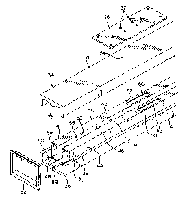
Referring now to the drawings, a railroad tie made pursuant to the teachings
of the
present invention is generally indicated by the numeral 10 and supports
substantially parallel
railroad rails 12 in a manner well known to those skilled in the art. 'fhe tie
10 includes an
outer casing generally indicated by the numeral 14 defining an upper surface
16, a lower
surface 18, and opposite side surfaces 20, 22. As shown in Figure 4, rail
support areas 24 are
defined upon the upper surface 16 of the tie 10, and tie plates 26 are mounted
on the rail
CA 02350460 2005-06-23
4
support areas 24 by fasteners 28. Conventional spikes 30 are driven through
apertures 32 in
the tie plates 26 and into the railroad tie 10 as will hereinafter be
described to secure rails 12
to the crosstie 10. End caps 32 close the opposite ends of the tie 12.
The casing 14 includes an upper section 34 and a lower section 36 which are
secured
together along their inner face 38 by an appropriate adhesive, preferably an
aeronautical
grade urethane adhesive available from MactacTM Corporation. The casing
sections 34, 36
are made out of a composite material as will be described hereinafter. The
casing 14, when
assembled, defines a cavity generally indicated by the numeral 40. A pair of
elongated,
tubular reinforcing beams 42, 44 are located in the cavity 40 adjacent the
side walls 20 and 22
respectively. Each of the tubular beams 42, 44 include an upper surface 46
Which engages
the upper section of the casing 34 when the tie is assembled, a lower surface
48, which rests
on the lower section 36 of the casing, a side surface 50, which engages the
inside of the
corresponding wall 20, 22 of the casing; and inner surfaces 52, 54, which face
each other and
cooperate therewith to define a longitudinal volume generally indicated by the
numeral 55
therebetween. The surfaces 46, 48, 50, 52 of the tubular beams 42 and 44
cooperate to define
a chamber 56 within each of the tubular beams 42, 44. Projections 58 project
from the upper
and lower sections 34, 36 of the outer casing 14 and into the cavity 40 to
engage the upper
and lower portions of the side walls 52 to thereby locate the beams 42 and 44
in their proper
positions within the cavity 40.
Each of the beams 42, 44 have a pair of apertures (only one of which is shown
for
each beam at 60) which extend below the rail support areas 24 of the crosstie
10. A pair of
composite inserts (only one of which for each beam is shown at 62 in Figure 4)
are installed
in each of the beams 42, 44 by pushing them in from the corresponding end of
the beam until
the inserts 62 register with the aperture 60. The inserts 62 are made out of
the same
composite material as is the casing 14, which will be described in detail
hereinafter. Each of
the side walls 52, 54 of the beams 42, 44 are provided with openings 64
(Figure 3) therein in
that portion of the side wall 52, 54 extending between the apertures 60. As
can be seen in
Figure 4, the ends of the beams 42, 44 terminate a short distance away from
the end of the
outer casing 14.
A reinforcing material generally indicated by the numeral 66 is pumped into
the
chambers 56 of the beams 42, 44 from both ends thereof after the upper and
lower sections of
CA 02350460 2001-05-10
WO 00/28144 PCT/US99/26$30
the casing are secured to one another and the reinforcing material is
simultaneously pumped
into the volume 55 between the beams. The reinforcing material pumped into
volume 55
enters that portion of the inner chambers 56 of the beams between the inserts
62 through the
openings 64. Accordingly, entire volume the cavity 40 is filled with the
reinforcing material.
S The reinforcing material b6 is preferably a fast drying concrete material
capable of being
pumped into the crosstie 10 as a liquid. Such a material is commonly referred
to as a
"flowable fill" concrete. Alternatively, a fast drying polyurethane material
may be
substituted.
The tubular reinforcing beams 42, 44 increase the stiffness of the crosstie
10, while
still providing shock absorbing and vibration dampening qualities in the
crosstie providing a
smooth ride for the train using the tracks supported by the crosstie. If
higher axle loads than
normal are to be accommodated, the thickness of the material of the tubular
members 42, 44
may be increased, thereby increasing the stiffness of the beam to accommodate
the higher
axle loads. The beams 42, 44 also resist crumbling of the concrete injected
into the chambers
56 within the beams since the beams 42, 44 are preferably made of steel and
resist flexing.
The composite material used in the upper and lower sections 34, 36 of the
casing and
for the inserts 62, as will be described hereinafter, are a mixture of
recycled plastic and crumb
rubber. This material withstands weathering, but is sufficiently deformable to
permit the
spikes 30, which hold the rails 12 to the crosstie 10, to be driven through
the openings 32 in
the plate 26, through the rail supporting areas 24 on the upper section 34 of
the casing 14,
through the aperture 60 in the corresponding one of the tubular beams 42, 44,
and into the
composite material of the inserts 62. Accordingly, spikes can be driven into
the crosstie 10 to
hold the rails 12 in place in exactly the same manner that spikes are used to
hold rails on
conventional wooden crossties.
Referring to the alternative embodiment of Figure 5 and 6, elements the same
or
substantially the same as those of the embodiment of Figures 1-4 retain the
same reference
character. In Figure 5, the two tubular beams 42, 44 are replaced by a single
tubular beam
generally indicated by the numeral 68 having an "H" cross section consisting
of longitudinally
extending arms 70 and 72 and a connecting portion 74. Insert 62 are installed
in the arms 70,
72 in the same way as they are installed in the tubular beams 42, 44; that is,
they are installed
through the ends of the beam 68. Concrete or an equivalent reinforcement
material is
CA 02350460 2001-05-10
WO 00/28144 PCT/US99/26830
6
pumped into the beam 70 to provide the necessary reinforcement. Referring to
the
embodiment of Figure 6, the tubular beams 42, 44 is replaced by a "W" shaped
beam
generally indicated by the numeral 76. W beam 76 defines a pair of upwardly
facing channels
78, 80 adjacent the side surfaces of the outer casing which are separated by
transverse portion
82 of the beam 76, which defines a longitudinal extending volume 84 separating
the channels
78, 80. Inserts 62 are installed in the channels 78, 80 but merely placing
them therein before
the upper section 34 is installed on the lower section 36. Concrete is pumped
into the volume
84 through the ends thereof and is installed directly into the channel 78, 80
before the
assembly of the outer casing 14 is completed by installing the upper section
34 and the lower
section 36 and by also thereafter installing end cap 32.
As discussed above, the outer casing 14 and the inserts 62 are a 50-50 mixture
of high
density polyethylene and crumb rubber. Preferably, the high density
polyethylene is obtained
from recycled plastics, such as found in plastic shampoo or detergent bottles,
etc. that have
been shredded as is known in the industry. The rubber particles are preferably
"crumb"
rubber articles obtained from recycled automotive tires that have been ground
and sized as is
known in the art. The size of the rubber particles is preferably "ten mesh"
according to
standard industry sizing methods. Rubber particles 14 may include
approximately 1 % or less
by volume long strand nylon fibers, which are commonly found in ground tires.
As discussed
above, the rubber particles provide a semi-resilient quality to the plastic,
thus preventing the
plastic from cracking upon the driving of the spikes 30 into the outer casing
and into the
insert 62. The mixture may be varied to contain as much as 60% shredded high
density
polyethylene and 40% crumb rubber to 40% shredded high density polyethylene
and 60%
crumb rubber.
The details of the composite material are given by the following example:
Example 1
A quantity of used polyethylene bottles from various sources is ground in a
shredder,
which produces non-uniform plastic particles of approximately one-half inch
square, and of
varying shapes and thicknesses. A quantity of used automobiles tires is ground
into crumb
rubber particles using any commercially available grinding method. Using a 10-
mesh screen,
which is a screen having 100 holes per square inch (10 rows and 10 columns of
holes per
CA 02350460 2005-06-23
7
square inch), the crumb rubber is sized to produce 10-mesh rubber particles.
Typically, the
10-mesh crumb rubber will include approximately 1% by volume long strand nylon
fibers
from the reinforcing belts found in most tires. The crumb rubber particles and
the shredded
plastics are combined into a 50-50 mixture by volume.
The composite crosstie is extruded using a Compact Compounder having a long
continuous mixer and a singe screw extruder, such as is manufactured by
PominiTM, Inc. of
Brecksville Ohio. The shredded polyethylene is placed in the first supply
hopper of the
co-extruder, and the crumb rubber particles are placed in a second supply
hopper. The
shredded plastic and the rubber particles are introduced into the barrel and
brought to a
molten state under pressure by the friction of the counter-rotating rotors.
The melted mix is
then fed into a single screw extruder, forced forward through the barrel by a
supply screw.
The plastic/rubber mix is then extruded through a die to form the upper casing
section 34. As
the casing section or insert is extruded, it is cooled and cut into standard
segments. The
casing sections may be cut to longer or shorter lengths as desired depending
on the length
requirements of the specific application.
Again, minor departures from the 50-50 ratio can be achieved without
significantly
reducing the beneficial properties of the final product. This variations can
be especially
useful when the weight or density of the final product needs to be tightly
controlled. The
natural graylblack color of the plastic/rubber matric will be suitable for
most applications.
However, a small amount of colorant can be added in order to produce a
different colored
member. For example, red dye can be added in order to produce a simulated wood
member,
and will give the appearance of cedar or redwood depending on the amount of
dye added.
Figure 7 illustrates a compact compounder 120 used to extrude the present
invention,
Compounder 120 is manufactured by Pomini~, Inc. of Brecksville Ohio.
Compounder 120
includes long continuous mixer 122 and single screw extruder 124. Long
continuous mixer
122 includes indeed hoppers 126, inlet 127, and barrel or mixing chamber 128.
Mixer 122
also includes discharge orifice 132 having discharge valve 133. A pair of
counter rotating
rotors 130 are disposed within chamber 128, and rotors 130 are driven by motor
131. Single
screw extruder 124 includes plasticating supply screw 134 as is commonly
employed in the
extrusion process. Single screw extruder 124 has inlet 138 which is in flow
communication
with discharge orifice 132 of mixer 122. Plasticating supply screw 134 is
mounted within
CA 02350460 2001-05-10
WO 00/28144 PCT/US99/Z6830
8
barrel or chamber 135, and is driven by motor 137. Discharge die 136 is
mounted to outlet
end 139 or extruder 124. Discharge die 136 is sized to match the desired corss-
sectional
dimensions of the extruded member.
Shredded plastic material 140 and crumb rubber 142 are fed from indeed hoppers
126
into long continuous mixer 122 and mixed under pressure by rotors 130 driven
by drive motor
131. If desired, a small amount of dye 144 may also be fed into the mix from
indeed hopper
126. Initially, discharge valve 133 at discharge orifice 132 is closed, which
maintains
pressure in chamber 128. Friction created by counter rotating rotors I30 work
the material
into a molten state, at which point valve 133 opens and allows molten material
to flow into
the extruder 24 through inlet 138. Motor 137 of extruder 124 drives supply
screw 134, which
urges the molten material under pressure towards outlet end 139 and through
die 136. The
extruded member (not shown) is cut into the desired length and cooled.