Note: Descriptions are shown in the official language in which they were submitted.
CA 02350712 2003-05-29
wo oor~a~6~ PCrli$~m9sa
METHOD t~CR COLOR t)t'T~CTION IN VIDEO IMAGES
Field of the invention
The present invention relates to a method and apparatus for detaching rotor in
video
images, and in particular to a method and apparatus for identifying pixels of
a given color
~o in a field of YUV video_
Background of the Invention
A variety of discrimination systems, operating in a range of circumstances,
use
color analysis as a basic tool. An example can be found in agriculture where a
green area,
such as a weed or other target plant, must be detected in an area of another
rotor, such
~5 as brown sail, in order to be sprayed.
PCTlCA95100595 (Rses) discloses a spray controller comprising a detector that
generates red, green and bias color signals across a field of view. The color
signals are
used to generate an output control signal 'its green' or 'not green' for
actuating a spray
nozzle on detection of something deemed to be green. Two possible algorithms
which
zo determine if something is 'green' rather than 'not green' are described.
One requires the
level of green to exceed each of the red and blue components in the color
signal. The
second algorithm requires the green level to exceed the red level and the blue
level to be
Isss than a set value.
~Jther approaches in the prior art for detecting whether a pixel has a target
color
2s involve the use of a took-up table that stores a value for every
combination of U and V
values, where U and V represent the color difference signals produced by a
video camera
and define the working color space. These approaches require urrxritry to
support the
addressing and read-baGc of the look-up table as well as a considerable amount
of
memory to store the table.
ao The hardware implementation of the ataove descxibed approaches requires
severe!
blocks of logic circuitry, ~eading to increased cost arid complexity of the
system.
CA 02350712 2001-05-11
WO 00/30362 PCT/IB99/O1980
The bandwidth of the chroma signal in a standard video signal is sufficient
only for
determining the chrominance accurately over a span of approximately nine
pixels
horizontally. In other words, the maximum amount of chroma change, from red to
green
for example, takes approximately nine pixels in a horizontal line. If pixel 1
is red, then the
closest pixel which can be green is pixel 10. The pixels between these two
will have
varying shades from red to green. Similarly, a signal transition from yellow
to blue must
pass through shades of either red or green along the transition. Thus, a
device for
detecting green pixels may "detect" green even though only blue and yellow are
present
in the scene viewed by the camera.
o Summary of the Invention
An object of the present invention to provide a simple and reliable video
imaging
color detection technique that avoids the problems and disadvantages of the
prior art.
According to one aspect of the invention there is provided a method of
identifying
a pixel of a given color in a field of YUV video by maximizing the pixel's
corresponding
signal in the color region of interest of a color space, and minimizing
signals in all other
areas of the color space. Additionally, the color region of interest is
rotated so as to be on
or near one of the U and V axes of the UV color space.
An advantage of the technique of the present invention is the minimal amount
of
logic circuitry required for its implementation. Only one comparator is needed
in addition
2o to the circuitry already existing within a conventional video camera, the
circuitry within the
camera performing the axis rotation and signal gain. Another advantage of this
technique
is that the number of false detections of pixels of a given color due to
insufficient chroma
bandwidth is greatly reduced.
The invention provides methods of processing a video signal to recognize
whether
25 a pixel belongs to a region of interest of a color space. A first method
comprises the steps
of, for each pixel, transforming the video signal into color difference
signals corresponding
to a set of defining axes of the color space; minimizing the signal gain for
all color
difference signals except for a color difference signal defining the region of
interest;
establishing a threshold value representing the minimum magnitude the color
difference
3o signal defining the region of interest must have when the pixel belongs to
the region of
interest of the color space; and comparing the color difference signal
defining the region
of interest with the threshold value to determine if the pixel is in the
region of interest. In
2
CA 02350712 2001-05-11
WO 00/30362 PCT/1B99/01980
a specific application useful for detecting green weeds to be sprayed in a
field, the axes
are a red axis and a blue axis and the region of interest is green. in this
case the gains of
the blue axis signal and positive red axis signal are minimized, leaving the
negative red
axis signal. The negative red axis signal is then compared to a threshold
value to
s determine if it is negative enough to be considered green.
A modification of the method comprises rotating one axis signal toward the
other
axis. Green has a negative blue component. To take advantage of this data the
blue axis
signal is rotated toward the red axis before the gains are applied.
In a further embodiment the entire color space is rotated to bring the color
region
of interest closer to, or onto, one of the axes.
According to a further aspect of the invention there is provided an apparatus
for
processing a video signal to determine when a pixel belongs to a region of
interest of a
color space, the apparatus comprising: a transformation circuit for
transforming the video
signal into color difference signals corresponding to a set of defining axes
of the color
~5 space; gain circuits for minimizing the signal gain of all color difference
signals except for
a color difference signal defining the region of interest; and a comparator
responsive to at
least one of the gain circuits for comparing the color difference signal
defining the region
of interest with a threshold value representing the minimum magnitude the
color
difference signal defining the region of interest must have when the pixel
belongs to the
2o region of interest, the comparator producing an output signal indicating
the pixel is in the
region of interest when the color difference signal defining the region of
interest exceeds
the threshold value. The apparatus may include a matrix for rotating the color
difference
signal corresponding to one axis toward the other axis.
An object of the invention is to provide an apparatus as described above in
2s combination with at least one spray nozzle mounted on the boom of a an
agricultural
sprayer, and means responsive to the comparator output signal for energizing
at least one
spray nozzle.
An application of the present technique is in agriculture, for weed detection.
A video
camera mounted on the spray boom of an agricultural sprayer may detect green
weeds
30 on brown soil by identifying the green pixels in the image captured as the
sprayer travels
in the field. With the aid of a controller, spray may be released upon the
weed, once the
weed is detected.
3
CA 02350712 2001-05-11
WO 00/30362 PCT/IB99/01980
Other advantages, objects and features of the present invention will be
readily
apparent to those skilled in the art upon consideration of the following
detailed description
of preferred embodiments and the accompanying drawings.
Brief Description of the Drawings
Fig. 1 represents the two-dimensional UV color space;
Fig. 2 represents the UV color space of Fig. 1 after the U axis signal has
been
rotated 13° to bring a blue or yellow region of interest onto, or close
to the U axis;
Fig. 3 is a more detailed representation of the two-dimensional UV color
space;
Fig. 4 is a block diagram illustrating the basic functions of an embodiment of
the
o invention wherein the color signals are supplied from a color video camera,
the axis
rotation and gain control being carried out external to the camera;
Fig. 5 is a block diagram illustrating a second embodiment of the invention
wherein
axis rotation and gain control are carried out by circuits within a color
video camera; and,
Figs. 6A - 6C are flow diagrams illustrating methods of detecting pixel color
~5 according to the invention.
Detailed Description Of The Invention
The method of the present invention is used to identify the color of pixels in
a field
of video using the color difference signals R-Y and B-Y. The color difference
signals
assume various names in the art, such as UV, CbCr, Cb'Cr', depending on the
video
2o encoding format. These various formats differ mainly in their scale and
relative magnitude.
More importantly, there are well-known methods for transforming from any
system to
another, and the exact system with which one works has no direct bearing on
the present
invention. For simplicity, the color difference signals are referred to as the
red (V) signal
and the blue (U) signal and the color space will be referred to as the UV
color space for
25 its 2-dimensional version at a constant luminance level, and the YUV color
space for its
3-dimensional version, where Y represents luminance.
Generally, video cameras perform mathematical transformations on the input
data
in order to produce a red and a blue color difference signal for each pixel.
These
calculations are performed to produce red (V) and blue (U) signals in
accordance with
3o specified standards for video signals, such as NTSC or PAL. Standard color
processing
involves applying gain to the U and V signals in order to generate levels of
appropriate
relative amplitude for the color being observed.
4
CA 02350712 2001-05-11
WO 00/30362 PCT/IB99/01980
In a first embodiment of the invention, colors that are predominantly along
one axis
of the UV color space, such as green, yellow, red and blue, are considered.
For simplicity,
the invention will be described primarily as it applies to the identification
of green pixels.
However, it will be appreciated by those skilled in the art that the
principles of the invention
s apply to other colors satisfying the above condition.
Figs. 1 and 3 represent the two-dimensional color space UV, defined by U and V
orthogonal axes, which correspond to the color difference signals B-Y and R-Y
from a
color video camera. In detecting green pixels, the negative V axis defines the
region of
interest because, as shown in Fig. 3, the green hue vector lies in the third
quadrant and
~o is displaced clockwise from the negative V axis so as to fall in the area
identified as
"green" in Fig. 1. Standard color processing methods can be modified to take
advantage
of this fact in identifying green pixels in a field of video. The modification
comprises the
step of distorting the output signal in favor of the identification of green
pixels. The
distortion is accomplished by setting to zero the gains for the U signals and
positive V
~5 signals. After performing these operations, the output signal is
substantially a red or V
signal wnich has only negative values and indicates only the negative red
content of the
scene captured by the video camera.
Based on this output signal, the identification of green pixels merely
requires
determining whether the red signal is sufficiently negative to be considered
green. Hence
2o a comparison of the red signal to a prescribed threshold value is necessary
for the final
decision of whether the pixel is green or not. Any red values below (more
negative than)
the prescribed threshold indicate the presence of green. The prescribed
threshold value
is arbitrarily selected, based on the level of green desired for the specific
application in
which the method is used.
25 The term "negatives is used in a relative sense rather than an absolute
sense. In
a preferred embodiment of the invention, the signals U and V are signed 8-bit
numbers
in two's complement format. The decimal value 128 defines the axis crossing
point in Fig.
1. As used herein a "negative" U axis signal is to the left of the crossing
point and a
"negative" V axis signal is below the crossing point.
3o Fig. 6A is a flow diagram illustrating the steps in a method as just
described. At S1
{step 1 ) the color of interest (the target color) is selected. At S2, gain is
selectively applied
to the signals U and V to minimize or reduce to zero all signals except for
those
CA 02350712 2001-05-11
WO 00/30362 PCT/IB99/01980
representing the region of interest. That is, if the color selected at S1 is
green, then at S2
the signals U and positive values of the signal V are minimized leaving only
(or primarily)
negative values of the V signals. At S3, the V signal, which now has only
negative values,
is compared with a threshold to determine if the V signal is sufficiently
negative to be
considered green.
Fig. 6B illustrates a modification of the method shown in Fig. 6A. This
modification
takes into account the fact that the target color (green) selected at S11 also
contains a
small amount of negative blue color, the hue vector for green being displaced
from the
negative V axis in a clockwise direction by 29.4 °. In order to
preserve this information and
to enhance the reliability and consistency of the green identification, the U
axis signal is
rotated by 29.4° counterclockwise at S12. This rotation effectively
places the green signal
information on or near the negative V axis.
Following the rotation, the green information is in substantially the same
region of
the color space as the negative V signal, and the points of green are
amplified by the
~5 negative V signal gain. The gains for U signals and positive V signals are
set to zero, and
the gain for negative V (green) signals is maximized at S13.
The identification of green pixels can then be done as previously outlined, by
comparing the negative V axis signal to a threshold value (S14) to determine
if the signal
is sufficiently negative to be considered green. fn terms of logic circuitry,
only one
2o comparator is needed to compare the red signal to a prescribed threshold
value. The
comparator may be either an analog or a digital comparator.
The rotation of the U axis signal is not limited to 29.4°. The optimum
amount of
rotation is dependent on the hue of the weeds to be detected. For example, if
the weeds
are a yellowish green, that is, the weed color has a high yellow component,
the detection
25 of yellowish green pixels is enhanced by rotating the U axis signal by more
than 29.4°.
On the other hand, if the weed color has a high negative red component then a
rotation
of less than 29.4° will provide maximum extraction of the color
information.
It will be understood by those skilled in the art that when the setting to
zero of the
signals gains is mentioned above, one requires in fact only a modification of
the gain, such
3o that a contrast between the region of interest and the rest of the color
space is achieved.
Likewise, the prescribed threshold value is negative red for the purpose of
green
identification, but in general, it may have any value, depending on the target
color, the
6
CA 02350712 2001-05-11
WO 00/30362 PCT/IB99/01980
color standards and encoding formats used, the exact modality of implementing
the
method within the logic circuitry and so on.
Fig. 6C illustrates a further modification of the method shown in Fig. 6A. In
this
method, after selecting a target color at S31, the entire color space is
rotated at S32. The
s degree or amount of rotation depends on the target color selected. Referring
to Fig. 3, it
is seen that yellow and blue lie generally about 13 ° off the U axis.
By rotating the entire
color space about 12 ° counterclockwise, both yellow and blue are moved
near the U axis.
At step S33, gains are selectively applied depending on whether yellow or blue
is the
selected target color. For example, if yellow pixels are to be detected, S33
minimizes
o positive and negative V axis signals and positive U axis signals so that the
negative U axis
signals are left as the dominant signals subjected to threshold comparison at
S34.
Fig. 4 is a block diagram of a system 10 that may be utilized to practice the
methods, described above, of identifying the color of a pixel. The system 10
utilizes the
color difference signals produced by a color video camera (not shown) and
comprises a
~5 rotation matrix 12 (required only to practice the methods shown in Figs. 6B
and 6C), U and
V gain amplifiers 14 and 16, a micro controller 18 and a pixel compare circuit
20.
In practicing the method shown in Fig. 6B, matrix 12 receives the color
difference
signals U and V produced by the camera and rotates one axis signal (assumed to
be the
U axis) toward another axis (assumed to be the V axis) in response to commands
from
2o controller 18. The resulting V axis signal, which now includes a negative
blue component,
is applied to V gain amplifier 16 and the signal U is applied to the U gain
amplifier 14. The
U and V gain amplifiers 14 and 16 are controlled by controller 18 so that the
output signal
is minimized for all regions in the color space except in the region of
interest. Assuming
the region of interest is green, the controller 18 controls the U and V gain
amplifiers to
2s minimize the U and positive values of V and maximize negative values of V.
The resulting
gain controlled signals are applied to pixel compare circuit 20 where the
signal
corresponding to the color region of interest is compared with a reference
value supplied
by controller 18 over signal path 22. Again assuming the region of interest is
green, each
negative V output from gain circuit 16 is compared with the reference value
and if it is
3o more negative than the reference value, pixel compare circuit 20 produces a
signal on
lead 24 indicating the pixel is green. The circuit 20 may be an analog device
but a digital
comparator is preferred.
7
CA 02350712 2001-05-11
WO 00/30362 PCT/IB99/01980
The method illustrated in Fig. 6C may be implemented by system 10 if the
controller
is programmed to apply commands to matrix 12 so as to rotate the entire color
space. The
method illustrated in Fig. 6A may be implemented by the system 10 if the
controller is
programmed to control matrix 12 so that no rotation is performed. Preferably
however,
matrix 12 is eliminated in this case and the color difference signals from the
video camera
are applied directly to the U and V gain circuits 14 and 16.
it will be recognized that the system 10, as depicted in Fig. 4, is capable of
recognizing a pixel of any target color. In applications where the target
color will not
change, one of the gain circuits may be eliminated. For example, in
recognizing green
weeds, the U axis gain circuit 14 is not required.
In Fig. 4, the axis rotation matrix 12 receives the color signal output of a
video
camera. However, conventional color video cameras typically include an axis
rotation
matrix for color signal processing, as well as a micro controller and gain
circuits. Therefore,
the invention may, and preferably is, implemented by directly connecting the
pixel compare
~5 circuit 20 to receive the color output signals from the camera. This
arrangement is
illustrated in Fig. 5.
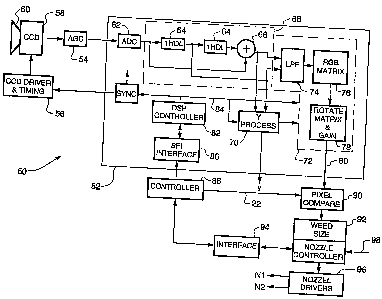
The system 50 shown in Fig. 5 may be implemented using a camera comprising a
Sony SS-1 3-chip set including a model CXD2163R digital signal processor (DSP)
chip 52,
a model CXA2006Q analog gain control (AGC) chip 54, and a model CXD2480R CCD
2o Driver and Timing Control chip 56. These three chips form a complete video
camera for
digitally processing analog signals produced by a CCD sensor 58. Sensor 58 is
mounted
on the boom (not shown) of an agricultural sprayer and is provided with a lens
60 so that
an image of a field in front of the sprayer is imaged onto the sensor. The CCD
Driver and
Timing circuits 56 control the "shutter speed" and readout of the analog color
video signal
25 from the sensor to AGC 54.
The analog video output signal from AGC 54 is applied to DSP 52 where it is
first
converted to a digital video signal by ADC 62. The output of ADC 62 is then
applied to a
contour correction circuit 68 comprising two delay circuits 64 and a summer
66. The
contour correction circuit is described in US patent 5,343,244 and produces
output signals
3o that are applied to a luminance signal processing circuit 70 and a
chrominance signal
processing circuit 72.
Within the chrominance signal processing circuit 72, the contour corrected
signal
8
CA 02350712 2001-05-11
WO 00/30362 PCT/IB99/01980
is first applied to a low pass filter (LPF) 74 and the output of filter 74 is
applied to a matrix
76 that develops the chroma signals R, G and S. The RGB signals, after white
balancing
and gamma correction by circuits not shown, are applied to a rotation and gain
matrix 78.
Matrix 78 normally transforms the RGB signals into the color difference
signals U (B-Y) V
(R-Y), alternately producing 8-bit signals U and V at its output 80. In
accordance with the
present invention, matrix 78 is also controlled to rotate the B-Y or U axis
signals toward
the R-Y or V axis as previously described, and minimize the U axis signals and
the positive
V axis signals.
The DSP chip 52 includes a DSP micro controller 82 for controlling, via a
serial data
bus 84, various circuits within the DSP, including the rotation and gain
imparted to the
color difference signals by matrix 78. The DSP chip also includes an interface
circuit 86.
In accordance with the invention, a system controller 88 is connected to the
DSP controller
82 via interface circuit 86. Controller 88 is connected via a serial interface
circuit 94, a
nozzle controller 92 and a CAN bus 98 to an input device (not shown) so that
an operator
~ 5 may select the target color and set the color threshold level, that is,
for example, how
negative the V signal on path 80 must be in order to be classified as green by
a pixel
compare circuit 90. The target color and is utilized in controller 88 to
develop the gain and
rotation signals. These signals are relayed to controller 82 which utilizes
the signals
to set the gains and rotation imparted to the pixel signals by matrix 78.
2o The target color is also utilized by controller 88 to develop the color
threshold signal
that is applied to pixel compare circuit 90. The color threshold level
provided by controller
88 may be a color corrected threshold which takes into account the luminance
in a field
of video. The color corrected threshold, developed from pixel luminance in one
field of
video as described in our above-referenced concurrently filed application, is
transferred
2s to pixel compare circuit 90 prior to the next field. Compare circuit 90
then compares the
color corrected threshold with the U/V signals from matrix 78.
Compare circuit 90 does not utilize the U signal when the target color is
green. The
circuit compares the color corrected threshold level signal with the values of
V produced
by matrix 78, and if V is more negative than the corrected threshold level
then an output
3o signal is made available to nozzle controller 92 indicating the pixel is
the target color, i.e.
green.
Pixel compare circuit 90 is a programmable logic array. In addition to
comparing for
9
CA 02350712 2001-05-11
WO 00/30362 PCT/IB99/01980
a target color, the circuit also counts the number of pixels of the target
color occurring on
each video scan line. Controller 92 samples the outputs from circuit 90 and
also receives,
via a CAN bus 98, the on and off times for the nozzles and a weed size value
input by an
operator. In this regard, a sprayer, which may spray a material over a path
having a width
s of up to 30 feet or more, is provided with a plurality of cameras. Each
camera is aimed so
as to view a different portion of the path to be sprayed. The field of view of
each camera
is divided into two regions and two nozzles N1, N2 are provided for spraying a
respective
region, the nozzles being close to, but trailing the camera. Controller 92
utilizes the
green/not green signal from compare circuit 90 to determine, for each scan
line, how many
green pixels have been detected within each region. If the number of green
pixels within
a region exceeds the weed size value supplied via CAN bus 98, then one of
nozzle
drivers 96 is actuated to activate the nozzle for that region.
Since the nozzles trail the camera, a nozzle is not turned on immediately upon
detection of a weed. A sensor and a conventional circuit (not shown) determine
the time
~ 5 at which a nozzle is turned on, based on the travel of the sprayer and the
camera to nozzle
distance.
The system 50 may be used to implement any of the methods illustrated in Figs.
6A-6C to recognize any color by proper programming of the DSP controller 82 to
set the
proper rotation and gains in matrix 78.
2o From the foregoing description it is evident that the present invention
provides a
simple buf reliable method of identifying pixels of a target color within a
field of video. In
terms of logic circuitry, the technique requires only one comparator, in
addition to the
circuitry required for standard processing of video images. The various
rotations that are
to be performed before the final comparison can be achieved by manipulating
the gains
25 in a video camera color transformation matrix.
Furthermore, the invention reduces the number of false detections due to
insufficient chroma bandwidth, as discussed in the Background section, by
minimizing the
color gain in all but the region of interest, and compressing all other
regions along one of
the U or V axes. Since regions which are not of interest are compressed along
one of the
3o U or axes and receive no signal gain, the transitions from one color to
another which
transition across the target color are reduced.
Numerous modifications, variations and adaptations may be made to the
particular
CA 02350712 2001-05-11
WO 00!3036Z PCT/IB99/01980
embodiments of the invention described above without departing from the scope
of the
invention as defined in the appended claims.
11