Note: Descriptions are shown in the official language in which they were submitted.
CA 02350961 2001-06-18
,i ',~
;.
"~
:j; ~j t '.
Mixer for Mixing At Least Two Flows Of Gas Or Other
Newtonian Liquids
., .,
4:~ The present invention relates to a mixer for mixing at least two flows of
gas or other
;:,Newtonian liquids, with a main flow channel through which the first flow of
gas passes, and
incorporated surfaces that are arranged therein, these incorporated surfaces
affecting the flow,
the incorporated surface being a vortex-generating disk that has a leading
edge that is
10oriented against the flow and about which the flow can move freely, the
shape of this leading
edge having a component that acts in the main direction of flow of the gas,
and a component
'I
;,
i that acts transversely to this.
In order to mix flows of gas or liquids in pipe lines or channels, given a
turbulent flow, one
1~~ requires mixing lengths of 15 to 100-times the diameter of the channel.
The length of this
' ! mixing section can be reduced significantly by using suitable static
mixers in the form of
incorporated bodies. However, in most of the systems that are usually used, a
major loss of
pressure has to be accepted if great demands are to be imposed with respect to
homogeneity
C, '
of the mixture that is produced. Many conventional mixing systems are also
restricted to
2~, simple geometry, e.g., cylindrical pipes or rectangular channels, and
cannot be used over
great lengths and in complex mixing-chamber systems.
i:.
US 4,527,903 describes a static mixer for use in a cooling tower; in this, the
incorporated
structures are delta-shaped or circular sheet-metal disks that the flow
strikes at an angle;
vortices are formed at their leading edges. The stationery and stable vortex
systems that are
so formed act in the wake of the flow; the components that are to be mixed are
rolled up in
the form of layers, which results in very rapid mixing with very small
pressure losses. These
so-called incorporated vortex structures have proved themselves in practice
because of the
short mixing sections that they make possible.
CA 02350961 2001-06-18
2
It is the objective of the present invention to describe a mixer for mixing at
least two flows of
,,
gas or other Newtonian liquids, which is characterized by rapid mixing in
short mixing
sections, even if a comparatively small proportion of an additional component
is to be mixed
in with a volume flow.
i
i ~.
f i
This objective has been achieved with a mixer having the features described in
the
introduction hereto, that is characterized in that the incorporated surface
has a chamber into
which a separate flow channel for a second flow of gas leads; and in that on
the rear side of
ai
i~i the incorporated surface that faces away from the inflow of the first gas
flow the chamber has
;,;
outlet openings into the first flow of gas.
I
;:
The advantages of such a mixer are seen, in particular, in those cases when a
relatively small
volume flow of the second component is to be mixed into a large volume flow of
a first
e';.
1~~ component and, at the same time, homogenization is to be achieved in a
short mixing section.
i
ty
The chamber into which the flow channel for the second flow of gas leads makes
it possible
to distribute the outlet openings for the second flow of gas according to the
manner in which
the mixer is operated, i.e., these outlet openings can be arranged with a
great degree of design
freedom. Thus, for example, it is possible to orient the outlet openings
against the main flow
2~'~ of gas, or else incorporate baffles that direct the flow of gas that
emerges from the outlet
openings into the area of the vortexes that are being formed by the leading
edges of the disc.
Application possibilities can be seen, for example, in denox plants for
scrubbing smoke gases
or when processing the dust collected by electro-filters. When scrubbing smoke
gas, NH3 or
25 ~ NH40H is to be mixed into the smoke gas that flows into the reaction
chambers, the
proportion of ammonia compounds amounting to only about 2%-mass. In this case,
using a
mixer according to the present invention permits rapid mixing of the two
components in a
short mixing section. The result of this thorough mixing it is that the
profile of the gas
and/or liquid flow that it is passed through is evened out, so that
perfonmance losses are
CA 02350961 2001-06-18
3
avoided. Despite the fact that they form extended and stable vortices, the
incorporated vortex
surfaces cause relatively little resistance to the flow since not all of their
surface acts as a
baffle; rather, their leading edges generate vortex fields that widen out
automatically in the
direction of flow, without any additional incorporated structures or baffles
being needed to
achieve this widening.
A further contribution to achieving homogenization in the shortest possible
mixing section
is made if, according to a preferred configuration of the present invention,
the outlet where
the second flow of gas enters the first flow of gas is located in the area of
the front half of the
disc. In this way, the second flow of gas that is introduced by way of the
separate flow
channel is picked up by the vortex fields that are generated in the front edge
area of the disc.
An additional advantage is that the chamber can be used to reinforce the
incorporated
surfaces. To this end, it is proposed that the chamber be provided with side
walls that are an
angle to the disc and stiffen the disc against bending loads and possible
oscillations.
With respect to the arrangement of the flow channel for the second flow of gas
within the
main flow channel, it is proposed that the separate flow channel be led to
this on the front
side of the disc. In this way, the installed volume of the separate flow
channel has no effect
2d' on the formation of vortices and their propagation on the rear side of the
disc.
,a
Finally, in order to achieve structural unification and thus simplification,
it is proposed that
the disc be supported in the main flow channel by struts, of which one is in
the form of a tube
and forms the separate flow channel. In this case, the flow channel assumes an
additional
a
i
2~~ static function in the arrangement of the incorporated vortex surfaces
within the main flow
i
r' : channel.
:i
One embodiment of the present invention is shown in the drawings appended
hereto. These
r.'drawings show the following:
~;t
CA 02350961 2001-06-18
4
Figure 1: a cross section through a denox plant of a smoke-gas scrubber with
an
incorporated vortex surfaces in the form of a disc that is arranged in the
main
flow channel ahead of the reactor;
5', Figure 2: a plan view of the rear side of the disc shown in Figure l;
Figure 3: a plan view of the rear side of a disc in a version that has been
modified with
respect to Figure 2;
Figure 4: a plan view of the rear side of a disc in a version that has been
further
modified with respect to Figure 2 and Figure 3;
10' Figure 5: a plan view of another embodiment;
Figure 6: a cross section of another embodiment of an incorporated vortex
surface that is
in the form of a disc;
Figure 7: a cross section that includes the main flow channel of another
embodiment of
r an incorporated vortex surface in the form of a disc;
15 Figure 8: a plan view of the rear side of the disc shown in Figure 7;
Figure 9: a plan view of the back of an incorporated vortex surface in the
form of a
delta-shaped disc;
Figure 10: a cross section through another embodiment of a disc-shaped
incorporated
vortex surface.
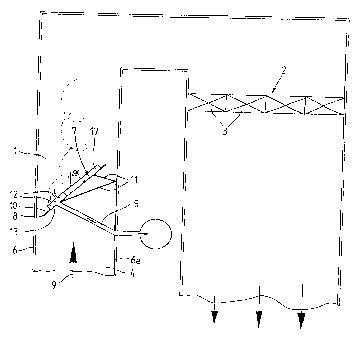
20 i
Figure 1 is a cross section through part of a smoke-gas nitrogen-removal plant
with a main
flow channel 1 in a rising arm of the plant and a reactor 2 in a downward flow
arm of said
plant. The reactor 2 is usually fitted with catalysts 3. When the plant is
operated, NH3 or
NH40H is mixed into the smoke gas that enters the main flow channel at
reference point 4.
25 ~ This is done by way of a separate flow channel 5 that passes through the
wall 6 of the main
flow channel 1. Next, in a manner that is described in greater detail below,
there is rapid
distribution and thus homogenization of the ammonia compound in the smoke gas,
so that
when it subsequently flows into the reactor 2, the ammonia compound is
distributed evenly
throughout the flow of smoke gas.
i
s
CA 02350961 2004-10-12
30482-2
The media are mixed by at least one incorporated
surface 7 that is arranged in the main flow channel 1. This
incorporated surface 7 is a so-called incorporated vortex
surface that is used to generate leading-edge vortices. The
5 leading edge 8 of the incorporated surface 7 that is
configured, for example, as a circular disc, which is
oriented against the flow in the main flow channel 1 and
about which the flow can move freely, has components that
act both in the direction of the main flow 9 and
transversely to this. Since, in addition, each incorporated
surface 7 is arranged at an acute angle a to the main
direction of flow 9 in the flow channel 1, vortex fields are
formed on each leading edge of the incorporated surface, and
these widen out conically as they move downstream. When
this happens, the individual vortices roll inward on the
rear side 10 of the incorporated surface 7, the rear side 10
being the side that faces away from the inflow of gas of the
first or minimum flow of gas. The vortices that are formed
on each individual leading edge 4 are largely stationary and
thus do not change position. Because of its rotation, each
vortex field forms a component of the flow that is
transverse to the main direction 9 in which the gas is
flowing, and this results in good mixing of the gas mixture
because of the associated pulse exchange across the
direction of flow.
The vortex-generating properties of the
incorporated surface 7, referred to above, are achieved in
conjunction with all of the so-called Newtonian liquids,
i.e., with gases and with such fluids that behave in much
the same manner as gases with respect to their flow
properties.
CA 02350961 2004-10-12
30482-2
6
The separate flow channel 5 for the second flow of
gas, which is preferably configured as a tube, extends right
into the main flow channel 1, where it opens out in the area
of the rear side 10 of the incorporated structures 7 that
faces away from the in-flowing first gas flow. The
incorporated surface 7 is so supported relative to the wall
6a of the main flow channel 1 by a plurality of struts 11
that the angle a subtended with the main flow direction 9 is
preferably between 40° and 80°, and is preferably
approximately 60°.
Figure 1 also shows that the outlet opening 12 of
the second gas flow is located at the level of the front
half of the disc or incorporated surface 7.
The plurality of outlet openings 12 are located in
the region of the front half of the incorporated surface 7,
the front half being the half of the surface 7 that is
closest to the inflow of gas of the first flow of gas. The
separate flow channel 5 leads to this on the front side of
the incorporated surface 7. The tube of the separate flow
channel 5 simultaneously assumes the static function of one
of the struts 11. These struts 11 are located on the front
side of the incorporated structure 7 so that they do not
affect the generation of the vortices on its rear side.
In order to ensure adaptation to particular
operating conditions, it is possible to change the
installation angle a of the disc 7 relative to the main
direction of flow 9, for example, by changing the effective
CA 02350961 2004-10-12
30482-2
6a
length of the struts 11. This modification or adjustment
can also be carried out when the mixer is being operated.
Figure 1 also shows that the separate flow channel
does not make an immediate transition into the outlet
5 openings 12; rather, the second flow of gas that is routed
through the flow channel 5 first enters a chamber 13 that is
arranged on the rear side of the incorporated surface 7.
Outlet openings 12 are then located in the outer side of the
chamber 13.
Figure 2 and Figure 3 show two possible
configurations of the chambers 13; in the Figure 2, the
outlet openings 12 are arranged around the centre line 14 of
the disc 7, whereas in Figure 3, the outlet openings are
split into two groups on both sides of the centre line 14,
so as to flow out into each area that is covered by the
left-hand or by the right-hand leading edge vortices.
The embodiment that is shown in Figure 4 differs
from the embodiment shown in Figure 3 in that it shows two
separate flow channels 5 through which two separate flows of
gas move into two separate chambers 13a, 13b. In this way,
it is possible to mix two different flows of
CA 02350961 2001-06-18
gas into the flow of gas that is passing through the main flow channel. The
separate chambers
13a, l3be can be located one behind the other. This is shown in Figure 5.
5Figure 6 shows that the outlet opening 12 of the chamber can be provided with
a deflector 15
so as to achieve the most favourable possible inflow of the second flow of gas
into the area of
the front leading edge vortices that are formed.
,i
Figure 7 and Figure 8 show that the outlet openings 12 can also be located in
the region of the
10- front face side 16 of the chamber 13. This results in an outflow that is
oriented so as to be
almost opposite the vortex field that is formed on the leading edges 8, so
that mixing takes
place very early.
Within the context of the embodiments of the present invention described
heretofore, the
15 incorporated surfaces 7 are essentially circular or elliptical. Figure 9
and Figure 10 show that
the incorporated surfaces can also be delta-shaped triangles with their apices
oriented against
the direction of flow. In addition, as can be seen in Figure 10, an additional
cowl 16 can be
provided for the outlet of the second gas flow, this having outlet openings 12
distributed
about its total circumference. The cowl 16 is set on the rear side of the
chamber 13 that is
20 arranged on the rear of the disc 7, although the chamber 13 can itself be
in the shape of a
cowl.
Finally, the Figures 1 to 10 show that since they are perpendicular to the
incorporated surface
7 or at least as an angle to this, the walls of the chamber 13 can reinforce
the incorporated
25 surfaces 7 with respect to bending loads. For this reason, the chambers 13
that serve as
distributors for the second flow of gas can include additional chambers 17,
which perform no
a
distribution function or flow functions, but are used exclusively to stiffen
the incorporated
i surfaces 7.
CA 02350961 2001-06-18
8
Key to Reference Numbers Used in Drawings
1 main flow channel
2 reactor
' 3 catalysts
4 entrance
5 separate flow channel
6 wall
6a wall
7 incorporated structure, disc
8 leading edge
' 9 main direction of flow
10 rear side
11 strut
12 outlet opening
13 chamber
13a chamber
13b chamber
14 centre line
15 baffle
16 cowl
17 chamber
a angle
N,