Note: Descriptions are shown in the official language in which they were submitted.
. . ~ . . . . . . . . . . . .
CA 02351190 2009-01-19
1
PIVOT CONNECTION ADJUSTMENT ASSEMBLY
Technical Field
This invention relates to an adjustment assembly which provides
for adjustment of the position of the pivot connection between two
parts.
Background of the Invention
One particular application of the present invention is in relation
to window assemblies having hinged stays to control movement of the
window during opening and closing thereof. It will be convenient to
hereinafter describe the invention with reference to this particular
application. It is to be understood, however, that this is not to be
taken as a limitation of the scope of the present invention. It will be
apparent from a reading of the following description that the
adjustment assembly could be used in other applications.
During the instaliation of windows into window frames, it is often
necessary to be able to adjust the position of the window so that it fits
properly within the window frame. Adjustable mechanisms for such
windows are known. For example, adjustment mechanisms are
described in U.S. Patent Nos. RE 35635 and 5,794,310. Both of these
patents describe an arrangement that includes a rivet which is inhibited
from rotational movement relative to one of the hinge members by
virtue of friction. Such an arrangement has the disadvantage that
various parts have to be manufactured with close tolerances to ensure
the frictional engagement meets the requirements of the adjustable
hinge.
CA 02351190 2009-01-19
2
Summary of the Invention
It is an object of the present invention to provide an improved
adjustment assembly, which alleviates the aforementioned
disadvantage. The improved adjustment assembly described herein can
be riveted loosely if desired in order to maintain its pivot mounting
element in place. However, it need not be riveted with the precision
and close tolerances required by prior art designs, with consequent
reductions in production cost and difficulty.
One aspect of the present invention provides an adjustment assembly
for enabling lateral adjustment of the position of a pivot connection of a
first
member relative to a second member, comprising: a rotatable pivot-mounting
element, which pivot-mounting element includes a first pivot-mounting section
having a first pivot axis, a second pivot-mounting section having a second
pivot axis that is generally parallel to and offset from the first pivot axis,
and an
engager section; and a locking member adapted to cooperate with the
engager section, the locking member being movable relative to the engager
section between a retention position and a release position, the locking
member preventing rotation of the pivot-mounting element when it is in the
retention position and allowing rotation of the pivot-mounting element when it
is in the release position.
In an installed position, the first and second pivot-mounting
sections are operatively connected to respective ones of the members
for enabling relative pivotal movement therebetween. The
arrangement is such that when the engagement member is in the
retention position, relative rotation between one of the pivot-mounting
sections and the member with which it is associated is inhibited.
When in use, the pivot-mounting element is fitted so that one
member is operatively connected to the first pivot-mounting section
and the other member is operatively connected to the second pivot-
mounting section. With the locking member in the retention position,
the second pivot mounting is inhibited from rotation relative to the
member to which it is operatively connected. The member operatively
connected to the first pivot-mounting member can, however, still pivot
relative to the first pivot mounting. To adjust the position of the first
pivot mounting relative to the member associated with the second
pivot mounting, the locking member is moved into the release position,
CA 02351190 2001-09-21
3
thereby permitting relative rotation between the second pivot
mounting and its associated member, this rotation enabling adjustment
of the position of the first pivot mounting relative to the member
associated with the second pivot mounting. The locking member is
then returned to its retention position.
In one form, the pivot-mounting element can include a body in
which the first and second pivot-mounting sections are.preferably in
the form of pins, the pivot axes of the two pins being offset or
eccentric with respect to one another. The engager section can be in
the form of a flange or collar and in the preferred form is disposed
between the pivot pins. The flange or collar can include a plurality of
engager sides which are adapted to cooperate with the locking member
when in the retention position to prevent rotation of the second pivot
pin relative to the member with which it is associated. The engager
sides can be angularly inclined with one another. This allows the
engager to be rotated so that a selected engager side or sides adopt a
position in which they cooperate with the locking member.
Preferably, the members with which the adjustment assembly is
to be used are elongated in form. For example, they can comprise the
hinge bars for a window assembly. The iocking member can be adapted
for sliding movement along one of the members. The sliding locking
member in one preferred embodiment can include a body portion having
a guide thereon. This guide is locatable within a slot on one of the
members which defines a track enabling sliding movement of the body
therealong. The body can further include a recess having side walls
which are adapted to cooperate with the engager member to limit
rotation of the second pivot pin when in the locked position. The
recess preferably has a cavity thereabove, the cavity inciuding an
upper wall, which in the locked position overlies the pin to hold it in
place on its associated member.
Alternatively, the locking member can be pivotally affixed to one
of the members. In this circumstance, the pivoting locking member
would be rotated into and out of locked position. In its locked position,
it would have edges that are adapted to cooperate with the engager
member to limit rotation of the second pivot pin. The pivoting locking
CA 02351190 2001-09-21
4
member can be provided with means for affixing it firmly in locked
position, such as a screw that can serve as its pivot and can also be
tightened to secure the pivoting locking member in the locked position.
This screw could also be loosened to allow the pivoting locking member
to be rotated into an unlocked position. The pivoting locking member
should also be provided with an upper member, which in the locked
position overlies the pin to hold it in place on its associated member.
Description of the Drawings
In order to enable a clearer understanding of the invention,
drawings illustrating preferred embodiments are attached, and in those
drawings:
Figure 1 is a schematic perspective view of a first embodiment
of an adjustment assembly according to the present invention, shown
in a release position.
Figure 2 is a similar view to that shown in Figure 1 of the
adjustment assembly, shown in the locked position.
Figure 3 is a schematic perspective view of a second embodiment
of an adjustment assembly according to the present invention, shown
in a locked position.
Figure 4 provides a cut-away perspective view of the second
embodiment of an adjustment assembly in a locked position.
Figure 5 provides a schematic perspective view of the second
embodiment of an adjustment assembly in an unlocked position.
Figure 6 provides a partially exploded schematic perspective view
of the second embodiment of an adjustment assembly in an unlocked
position.
Figure 7 provides a schematic cross-sectional view illustrating
the second embodiment in an unlocked position.
Figure 8 provides a schematic cross-sectional view illustrating
the second embodiment in locked position.
CA 02351190 2009-01-19
Figure 9 provides a schematic cross-sectional view illustrating a
variation of the second embodiment in a locked position.
Figure 10 provides a schematic cross-sectional view illustrating
the second embodiment with its second pivot pin in a first position.
5 Figure 11 provides a schematic cross-sectional view illustrating
the second embodiment with its second pivot pin in a second position.
Figure 12 provides a schematic cross-sectional view illustrating
the second embodiment with its second pivot pin in a third position.
Figure 13 provides a schematic cross-sectional view illustrating
the second embodiment with its second pivot pin in a fourth position.
Description of the Invention
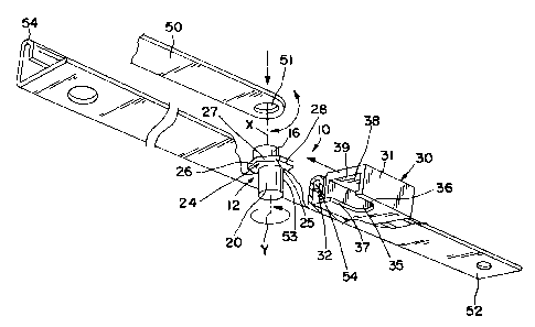
Referring to the drawings for both preferred embodiments, it will
be seen that the adjustment assembly generally indicated at 10 is for
use in adjusting the lateral position of the pivot axis between a first
member 50 and a second member 52. In the embodiments shown, the
members can form part of a window opening and closing mechanism,
such as, for example, the mechanism described in International Patent
Application No. PCT/AU98/00982. As shown, the member 50 is in the form of
a connecting arm and the member 52 is in the form of a runner frame.
The assembly 10 includes a pivot-mounting element 12
comprising a first pivot-mounting section in the form of a pin 16 having
a central pivot axis X. The pivot-mounting element 12 further includes
a second pivot-mounting section comprising a second pin 20 with a
pivot axis Y. As can be seen from Figure 1, the pivot axes are offset
or eccentric with respect to one another.
The first pivot pin 16 is adapted to be received within hole 51 in
member 50 so that member 50 can pivot thereabout. The second
pivot pin 20 is received within a hole 53 in the second member 52 so
that, under selected conditions, it can rotate within that hole.
CA 02351190 2001-09-21
6
The pivot-mounting element further, includes an engager section
24 in the form of a flange or collar 25. As shown, the flange 25 is in
the form of a hexagonal shaped collar with a plurality of sides, three of
which are identified by the reference numerals 26, 27, and 28, the
flange or collar 25 being disposed between the pivot pins 16 and 20.
In the first preferred embodiment illustrated in Figures 1 and 2,
the assembly further includes a locking member 30 which is movable
relative to the pivot-mounting element 12 between a release position
as shown in Figure 1 and an engaged or locked position as shown in
Figure 2. The locking member 30 includes a body portion 31 having a
guide 32 thereon. Guide 32 is locatable within a slot 54 on the member
52 which defines a track enabling sliding movement of the body
therealong.
The body further includes a recess 35 having side walls 36 and
37 which are adapted to cooperate with the engager section 24 to limit
rotation of the second pin when in the locked position. The recess 35
has a cavity 38 thereabove, the cavity 38 including an upper wall 39
which in the locked position overlies pin 16 to hold the first member 50
in place thereon.
The operation of the assembly 10 shown in the drawing figures
for both preferred embodiments will hereinafter be described with
reference to its particular use in connection with hinge mechanisms for
window assemblies. Referring to the drawings, the member 52 is in the
form of a runner frame of a hinge mechanism, this runner frame being
mounted to a window frame, and member 50 is in the form of a hinge
link, which is operatively connected to the window. The pivot-mounting
element 12 operatively interconnects the runner frame 52 and hinge
arm 50. The second pivot pin 20 is received within a hole 53 in the
runner frame 52. Second pivot pin 20 is adapted to be rotated within
the hole 53 when the locking member is in the release position. The
engager section 24 is adapted to rest on the upper surface of the
runner frame. The hinge arm 50 is adapted to be received on first
pivot pin 16 via hole 51 and is able to freely pivot about first pivot pin
16.
CA 02351190 2001-09-21
7
In the first preferred embodiment illustrated in Figures 1 and 2,
the locking member 30 is mounted to the runner frame 52 via guide
32. Slot 54 on runner frame 52 forms a track for guide 32, enabling
sliding movement of the locking member 30 along runner frame 52.
When the locking member 30 of the first embodiment is in the
release position (that is, the locking member 30 is spaced from pivot-
mounting element 10), the second pivot pin 20 can be rotated relative
to the runner frame 52. Rotation of the second pivot pin 20 causes
displacement of the first pivot pin member 16 relatively to the runner
frame and thereby displaces the pivot axis X of member 50 relative to
the runner frame. When the pivot axis X of first pivot pin 16 is in the
desired position, the locking member 30 is moved into the retention
position in which it is located with the sides of recess 35 contacting
respective selected sides of the engager member. When this is done,
first pivot pin 16 is disposed within recess 38 and member 50 is
prevented from lifting off first pivot pin 16 as a result of top wall 39.
In this position, second pivot pin 20 is locked with respect to
runner frame 52. Member 50 can pivot on first pivot pin 16. The
opening to recess 38 is sufficiently wide to enable the desired pivoting
movement of member 50 relative to the runner frame 52. The locking
member 30 can be removed from the frame 52 and can serve as a tool
for rotating second pivot pin 20.
In the second embodiment illustrated in Figures 3 through 13, a
pivoting locking member 60 can be rotated into and out of locked
position. In its locked position (as illustrated in Figures 3, 4, and 8
through 13), pivoting locking member 60 has edges (denoted generally
by arrow 61 in Figure 7) that are adapted to cooperate with engager
section 24 to limit rotation of the second pivot pin 20. The pivoting
locking member 60 can be provided with means for affixing it firmly in
locked position, such as a screw 62 that can serve as its pivot and can
also be tightened to secure it in the locked position. Screw 62 can also
be loosened to allow the pivoting locking member 60 to be rotated into
an unlocked position (as illustrated in Figures 5 through 7). The
pivoting locking member 60 is also provided with an upper member 63,
which in the locked position overlies the first pivot pin 16 and serves to
CA 02351190 2001-09-21
8
hold member 50 in place on first pivot pin 16 adjacent runner frame
52. Two variations of pivoting locking member 60 are illustrated. The
first variation, as illustrated in Figures 3 through 6 and 9, only
interfaces with two edges of engager section 24. The second
variation, as illustrated in Figures 7, 8, and 10 through 13, interfaces
with four edges of engager section 24 and provides a more positive
grip to prevent rotation thereof.
Finally, it is to be understood that the inventive concept in any of
its aspects can be incorporated in many different constructions so
that the generality of the preceding description and the claims that
follow is not to be superseded by the particularity of the attached
drawings. Various alterations, modifications, and/or additions can be
incorporated into the various constructions and arrangements of parts
without departing from the spirit or ambit of the invention.