Note: Descriptions are shown in the official language in which they were submitted.
CA 02351264 2008-10-20
1
Title: MACHINE FOR REPEATEDLY FOLDING A SHEET OF FOIL
TO CREATE A LAYERED EDGE
Field of the Invention
This invention relates to machines for cutting and folding sheets of aluminum
foil.
Background of the Invention
Machines for dispensing a predetermined amount of material from a sheet roll
of
material are known in the prior art. U.S. Patent 3,949,918 issued April 13,
1976
discloses a heavy gauge plastic film dispenser with a motor for semi-automatic
dispensing. The motor of the dispenser operates for a pre-determined time
interval
allowing an amount of material to be dispensed. The dispensed material is
manually torn
off by cut-off blade on the dispenser, which is used in the packing of meat
cuts.
Using small sheets of aluminum foil in a hair coloring process is well known.
U.S.
Patent 5,816,268 issued October 6, 1998 teaches a hair highlighting method and
apparatus using sheets of foil. Experts in hair coloring are familiar with how
aluminum
foil is used, but typically the procedure involves wrapping hair in aluminum
foil. A hair
coloring procedure which uses aluminum foil can be more expensive than other
procedures. One cheaper method for coloring hair involves the use of a cap
with holes in
it.
CA 02351264 2001-06-26
-2-
Upwards of one hundred small sheets of aluminum foil can be required for hair
coloring using the foil method. Also. in this known method the sheets need to
be folded
along one of the edges. Edge folding prevents bleeding of' the colorant and
adds edge
strength to the foil. It becomes readily apparent how time consuming a manual
hair coloring
procedure can be if many sheets have to be cut and folded manually from a roll
of aluminum
foil. A machine which can automatically cut and fold aluminum foil could
greatly reduce the
effort required to color hair by the alutninum foil method.
Summary of the invention
According to one aspect of the invention, a machine for cutting and folding
sheets of
aluminum foil dispensed from a roll includes means for mounting a roll of
aluminum foil so
that aluminum foil can be advanced through the machine. Two adjacent rollers
can be
electrically driven to advance aluminum foil by frictional force from the
roll. The machine
further comprises means for cutting off a sheet of aluminum foil after it has
passed between
the rollers and means for folding an edge of a cut sheet produced by the
cutting means.
Means for controlling the cutting means ensures that the aluminum foil is cut
only during
predetermined intervals.
In an alternate embodiment the invention comprises a machine for cutting and
folding sheets
CA 02351264 2001-06-26
-3-
of aluminum foil dispensed from a roll, the machine comprising a machine for
folding sheets
of foil, the machine comprising;
(a) a means for controllably advancing a sheet of foil along a sheet feed
direction
through said machine;
(b) a means for folding an end of said sheet such that said end including a
folded part;
c) a means for discharging said sheet from said folding machine such that said
trailing
end including a layered edge
Preferably wherein said folding means including a folding assembly for
creasing or folding
an end into said folded part.
Preferably wherein said folded part is initially preferably an upstanding
vertical section.
Preferably wherein said folded part is initially preferably an upstanding
vertical section
connected to a downwardly disposed tail section foi-ming an inverted V shape.
Preferably said discharge means further includes a means for flattening said
folded part, to
form a layered edge.
Preferably wherein said further folding means includes a knockdown roller for
interacting
CA 02351264 2001-06-26
-4-
with said folded part and further folding said folded part.
Preferably wherein said knockdown roller is preferably made of a soft
resilient material for
engaging with a top edge of said folded part thereby further folding and
knocking down said
folded part.
Preferably wherein said knockdown roller is preferably made of a resilient
foam.
Preferably wherein said folding assembly includes V shaped folding member and
a
cooperating composite blade for initially folding an end of said sheet.
Preferably wherein said folding mernber and cooperating composite blade forms
a folded
part in an end of said sheet which is preferably an inverted V shape;
In an alternate embodiment the invention comprises a machine for cutting and
folding sheets
of aluminum foil dispensed from a roll, the machine comprising;
(a) a means for mounting a roll of aluminum foil so that aluminum foil can be
advanced through said machine.
CA 02351264 2001-06-26
-5-
(b) two adjacent nip rollers rotatable by a drive system to advance aluminum
foil by
frictional force from said roll,
(c) a knife mechanism for cutting off a sheet of aluminum foil after it has
passed
between said nip rollers;
(d) a folding mechanism for producing a folded part of a cut sheet produced by
said
knife mechanism; and
(e) means for controlling and operating said knife mechanism so that the
aluminum
foil is cut only during predeterniined intervals.
Preferably wherein said folding mechanism including a folding assembly for
creasing or
folding an edge into said folded pail.
Preferably wherein said folded part initially is preferably an upstanding
vertical section.
Preferably wherein said folded part initially is preferably an upstanding
vertical section
connected to a downwardly disposed tail section forming an inverted V shape.
In an alternate embodiment the invention comprises a method of folding sheets
of foil, the
method comprising the steps of:
a) advancing a sheet of foil through a folding machine;
CA 02351264 2001-06-26
-6-
b) folding a trailing end of said sheet such that said trailing edge including
a folded
part; and
c) discharging said sheet with a layered edge from said folding machine.
Preferably wherein said folded part initially is preferably an upstanding
vertical section.
Preferably wherein said folded part initially is preferably an upstanding
vertical section
connected to a downwardly disposed tail section forming an inverted V shape.
Preferably further including the step after step b) of b) further folding said
folded part.
Preferably wherein said folding machine including a knockdown roller for
interacting with
said folded part and further folding said folded part.
Preferably wherein said knockdown rul ler is preferably made of a soft
resilient material for
engaging with a top edge of said folded part thereby further folding and
knocking down said
folded part.
Brief Descrintion of the Drawings
.
Figure 1 is a top view of the inachine of the present invention.
CA 02351264 2001-06-26
-7-
Figure 2 is an isometric view illustrating the moving parts inside the
machine.
Figure 3 is a side view of cutting knife and folding apparatus used in the
present
invention, this view showing the foil strip prior to cutting.
Figure 4 is another side view of the cutting blade and folding apparatus, this
view
showing the foil strip being cut and folded and showing the blade at top of
its stroke;
Figure 5 is yet another side view of the cutting blade and folding apparatus,
this view
showing the cut-off sheet beir-g pulled forwards to a knock-down roller and
having
a creased lagging edge;
Figure 6 is still another side view of the cutting knife and folding
apparatus, this view
showing the cut-off sheet after it has been folded by the knock-down roller.
Figure 7 a) through c) are cross sectional view of alternative embodiments for
the
knock-down roller used in the present invention; and
Figure 8 is a plan and cross-sectional view of a small aluminum folded sheet
produced by the machine, of the invention.
Figure 9 is still another side view of the cutting knife and folding
apparatus, this view
showing the cut-off sheet aftei- it has been folded by the knock-down roller.
Figure 10 is still another side view of the cutting knife and folding
apparatus, this
view showing the cut-off sheet after it has been folded by the knock-down
roller.
Figure 11 is an alternate embodiment and a side view of cutting knife and
folding
apparatus used in the present invention, this view showing the foil strip
prior to
CA 02351264 2001-06-26
-8-
cutting.
Figure 12 is a schematic cross-sectional view of a cut sheet passing under a
knockdown roller.
Figure 13 is a schematic cross-sectional view of the cut sheet as it is
advancing
through a knockdown roller.
Figures 14 is a schematic cross-sectional view of a cut sheet passing under a
knockdown roller, with folded part knocked down.
Figure 15 is a schematic cross-sectional view of the cut sheet shown in Figure
14
after it has passed through nip rollers producing a layered edge.
Figure 16 is a schematic cross-sectional view of cut sheet further advancing
through
knockdown roller wherein folded part is further folded.
Figure 17 is a schematic cross-section view of cut sheet showing folded part
of sheet
being further folded by nip rollers into a further layered edge.
Detailed DescriRtion of the Preferred Embodiment
Figure 1 illustrates a machine 10 used for producing small aluminum foil
sheets for
haring coloring. The machine 10 accepts a roll of foil 14, advances foil from
the roll through
the machine and chops foil dispensed from the roll into small sheets such as
sheet 16
illustrated in Figure 8. The small sheets exit the cutting device at a
dispenser end 20.
Machine parts including several rollers are mounted between two machine frame
sidewalls
CA 02351264 2001-06-26
-9-
22 and 24. The machine parts which are rotatable are of course rotatably
mounted on
suitable shafts or stub shafts that extend through round holes in the
sidewalls. The sidewalls
22 and 24 are made of steel or some other rigid metal. The sidewalls are also
preferably
rectangular in shape so that the machine 10 has a box like appearance when
assembled. In
a preferred embodiment, the box shaped machine 10 is relatively portable. The
machine is
preferably constructed so that the machine is stable on a flat surface without
securing means,
even during its operation. The preferred machine also has a cover (not shown)
extending
over the top.
In Figure 1, roll 14 is rotatably mounted in the machine 10 on roll mount 26.
This roll
14 preferably has a width of 5 inches, being the width used for hair coloring.
Typically a 5
lb. Roll of foil is suitable for this machine. The roll mount 26 is attached
at its respective
ends to the sidewalls 22 and 24, and the mount includes a spring loaded pinch
mechanism
which engages two roll apertures centrally located on the ends of the roll.
Referring to
Figure 2, foil web or sheet 30 shoulcl unwind smoothly and evenly with minimal
constant
tension. The sheet 30 is advanced from the roll 14 through two rear nip
rollers 32 and 34.
The nip rollers frictionally engage an(i position the sheet so that it
advances properly into a
knife cutting 37 and folding assemblv 36. Ensuring contact between the roller
32 and the
sheet 30, as well as contact between the sheet and the roller 34 requires that
the two rollers
be positioned closely together. The preferred nip rollers 32, 34 have a series
of spaced apart
CA 02351264 2001-06-26
-10-
grooves 35 fonned therein.
The web is then cut and folded in a process described hereinafter and
illustrated in
Figures 3 through 6. The cut sheet 16 will advance out of the assembly 36 and
onto a
stationary knock-down table 38. Shaft support 39 keeps the table relatively
fixed in place.
The table 38 is inclined to properly direct the sheet 16 so that it will
advance through two
front nip rollers 40 and 42.
The nip rollers 40 and 42 can be constructed in a manner similar to the
rollers 32 and
34. Although all rollers rotate together, nip rollers 40 and 42 rotate
slightly faster than the
rear nip rollers 32 and 34. This speed difference allows the leading edge of
foil to stay ahead
of the lagging web leading edge as they travel through the machine web path
and out. It also
keeps the web taught between front and back rollers before cutting as
illustrated in Figure
3. The rollers 32, 34, 40 and 42 ai-e spring tensioned in order for them to
apply some
pressure to the foil surface. Reference is made to U.S. Patent 3,949,918 which
teaches rollers
similar in principle to these i.e. pairing two rollers and passing a sheet of
material between
them.
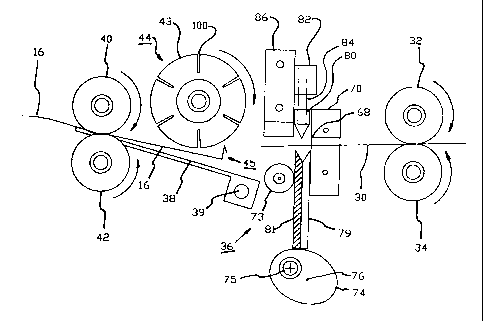
As the sheet 16 advances out of the assembly 36 (Figure 5), it also passes
under a
knock-down roller 44. A preferred diameter for the roller 44 is 1.25". The
roller has a
CA 02351264 2001-06-26
- 11 -
transverse, centrally extending bore which could be 0.75" in diameter.
Protruding members
43 which are evenly spaced apart by ti-ansverse grooves 100 should preferably
be made of
open cell foam which is a soft material and which allows the members 43 to be
easily
deformed. In a preferred embodiment, the roller 44 including its members 43 is
made of a
single piece of foam.
The roller 44 is positioned approximately an eighth of an inch above the table
38 to
work effectively. As illustrated in Figure 5, folded part 45 of the sheet 16,
has an inverted
V shape and will come in contact with the surface of the roller 44. The folded
part 45
interacts with the roller 44. In particular, the soft open cell foam or one of
the grooves 100
catches the part 45. The folded pail is rolled forward by the knock-down
roller which is
rotating at a faster rate than the speed at which the web sheet is advancing.
The interaction
further folds the sheet 16 as Figure 6 illustrates. Now past the roller 44,
the sheet 16 has a
folded edge 150 which can be folded two or more times. The folded edge 150
will be
flattened when it passes through the rollers 40 and 42.
In Figure 1, motion control assembly 45 controls the advancement of foil in
the
machine 10. The assembly 46 includes a number of spur gears 50, 52 and 54 and
timing
pulleys 56 and 58. A timing belt 50 passes over the pulleys ensuring that the
rollers rotate
together. The front rollers 40, 42 preferably rotate slightly faster than the
rear nip rollers
CA 02351264 2001-06-26
allowing the leading sheet of foil to stay ahead of the lagging web leading
edge. In one
preferred version of the machine, the spur gears provide a 3:1 turning in
ratio between the
front rollers 40, 42 and the knockdown roller 44. One skilled in the art will
appreciate that
there are various means from control] ing and synchronizing rotational motion,
and that the
assembly 46 could be modified in various obvious ways which would still
achieve the
disclosed motion requirements.
Advancement of foil through the machine 10 is controlled by a standard
electric
timing circuit which is not illustrated. In one version of the machine, an
Electromatic Timing
Relay (No. 5110166-120) was used. The electric circuit operates an electric
motor 64, the
motor 64 in turn rotating the rollers 32 and 34. "The motor 64 can be rigidly
mounted on the
sidewall 24. Jam detectors of knowii construction can be provided in the
machine to stop
advancement in the case of a foil jani. There is also a motor for the
operation of the knife
cutting and folding assembly 36. The two motors preferably do not operate
simultaneously.
Rather a repeated cycle exists in the machine 10, including a foil advancing
period and a
shearing period. Although not illustraled, it will be appreciated by one
skilled in the art that
there is a suitably programmed microprocessor (which can be a standard
microprocessor) for
controlling operation of the machine. The timing circuit is energized by
turning on a main
electrical power switch (not shown).
CA 02351264 2001-06-26
- 1 3 -
Figure 3 through 6 illustrate stages during which the sheet 30 is cut and
folded. The
sheet 30 is cut at a point indicated at 68 (Figure 3) on the rear side of
blade housing 70.
Specifically the sheet is cut when composite blade 72 rises past the cutting
point 68. Two
oval cams 74 (only one being in view in Figure 3) cyclically raise and lower
the blade 72.
Any other suitable means to raise and lower cornposite blade 72 can be
utilized. Roller 73
guides the blade through its vertical rnotion. Cam shaft 75 is offset from a
central axis 76
of the cams extending perpendicular to the plan of view. In the illustrated
embodiment, the
cams 74 rotates in a counterclockwise direction. In another embodiment of the
machine, the
action of lifting and lowering the blade would be achieved by electromagnetic
solenoid use.
One skilled in the art and familiar with electromagnetic solenoids will
appreciate how this
minor modification can be made.
Note that the preferred blade 72 is a two part composite blade with one part
79
preferably being made of steel (for cutting purposes) and the other part 81
being made of a
non gall.ing material such as ultrahigh rnolecular weight (UHMW) plastic
material or brass
or other suitable material. The canis 74 can also be made of UHMW plastic or
other
material.
After the aluminum foil is cut, the folding process proceeds. A stationary
folding
member 80 is attached to a holding bracket 82 by a shaft 84. As an alternative
to the
CA 02351264 2001-06-26
-14-
illustrated shaft 84, the folding membei- 80 and the shaft could be a single
member as shown
in Figure 1 l. The bracket 82 is attached to house 86. The pointed shape of
member 80
facilitates the folding process. As illustrated in Figure 4, folding of the
aluminum foil can
occur at an edge 90 and at composite blade edge 92. The edge 90 is designed to
create an
approximately 90 fold as illustrated. The angle for the fold created by the
edge 92 is acute
(about 30 ).
The composite blade is lowered, and the cut sheet as well as the sheet 30 are
advanced
as illustrated in Figure 5. When the blade is lowered towards its normal rest
position, it
engages a micro switch that indicates when the blade has reached the rest
position and
signalling to the microprocessor to shut off power to the knife motor. The
blade motion is
then stopped. At this time also the microprocessor engages power to the roller
motor. The
folding member is opened at a predetei-mined time as explained below. As the
cut sheet is
advanced, the crease if folded over bv the knockdown roller as it passes under
it. The cut
sheet is pressed by the nip rollers 40 and 42 as it advances out through a
discharge opening.
One skilled in the art will appreciate that it would be possible to design the
machine
so that folding step is omitted. This would be achieved by not having the
blade come in close
proximity to the folding member as illustrated in Figure 4. The machine can
also be designed
with a lever allowing two modes of operation. In one mode the cut sheet would
be folded,
CA 02351264 2001-06-26
-15-
and in the other the cut sheet would not be folded. Accordingly, this optional
feature is
intended to fall within the scope of the invention.
Figure 7 (a) through (c) illustrates alternative embodiments for the knockdown
roller
44. The transverse grooves in these embodiments are less deep than the
transverse grooves
100. Roller 120 has twelve transverse grooves 122. Circumferential spacing
between groove
centres is 0.324". Rollers 126 and 132 have sixteen and eight transverse
grooves 128 and
134 respectively. The circumferential spacing for the grooves 128 and 134 are
0.245" and
0.36". Again only the protruding metnbers can be foam, or the entire roll can
be a single
foam piece.
Figure 8 illustrates the small aluminum foil sheet 16 produced by the machine.
The
length of this sheet will vary; however the sheet width should be about 5".
The layered edge
150 is preferably about three layers of aluminum foil. The dimensions of the
edge 150 are
about 5" by 1/8". The sheet length can be controlled by adjusting the cycle so
that the sheet
advances for a longer or shorter period of time. It will be appreciated that
the sheet 16 will
be longer if this period of time is longer.
In one version of the machine, the upper moving components are mounted on a
separate pivoting frame so that these components can readily be raised from
their working
CA 02351264 2001-06-26
- 16-
position in order to feed the aluminum foil to the front nip rollers 40, 42.
Thus the top front
and back rollers, the knockdown roller. the blade housing and fold guide are
mounted on this
upwardly pivoting frame. The operator can then grasp the leading edge of the
foil and pull
it to a point just past the front nip rollers. After ensuring that the web is
centred, the upper
frame can be closed to a spring locked position and the machine is ready to
operate by
pushing the start switch.
Referring now specifically to Figures 12 through 17 inclusive, which shows
schematically how a cut sheet 16 interacts schematically with knockdown roller
44. In other
words, we are showing schematically how folded part 45 of cut sheet 16
interacts with
knockdown roller 44. Figure 12 roughly corresponds with the position shown in
earlier
Figure 5 of cut sheet 16.
A trailing end 250 of cut sheet 16 has been folded by folding assembly 36
leaving an
upstanding folded part 45 in trailing end 250 of cut sheet 16.
Folded part 45 preferably is an inverted V shaped section 228 and includes the
following major portions, namely in an upstanding vertical section 224 which
is folded at top
edge 232 and connected to a downwai-dly disposed tail section 222 which ends
at tail end
230.
CA 02351264 2001-06-26
-17-
More specifically and to the best of the inventors knowledge, although it is
not totally
certain how folded part 45 interacts with knockdown roller 44, by stopping the
machine at
various points of the cut sheet 16 interacting with knockdown roller 44,
Figures 12 through
17 illustrate, how folded part 45 interacts with knockdown roller 44.
One will note that the cut sheet 16 is fed along a sheet feed direction 236 as
indicated
by the arrow in Figure 12. One will also note that knockdown roller 44 is
rotating in rotation
direction 220 and thereby as cut sheet 16 is fed into rotating knockdown
roller 44, the soft
foam 226 roller of knockdown roller 44 will interact with top edge 232 of
folded part 45.
When top edge 232 impinges onto the outer diameter of knockdown roller 44, the
soft
foam 226 engages a top edge 232 of the upstanding vertical section 224 of the
folded part 45.
By engaging with top edge 232 of the folded part 45, it would continue to
fold, folded part
45 about bottom edge 234 as shown in Figure 13.
As cut sheet 16 is further fed in sheet feed dii-ection 236 into knockdown
roller 44, it
would eventually completely fold the vertical section 224 and the tail section
222 onto itself
and onto the cut sheet 16 producing a layered edge 150 as shown in Figure 14.
The finished product has a layered edge 150 once the sheet feed exits through
nip
CA 02351264 2001-06-26
-1s-
rollers 40 and 42. Layered edge 150 is three layers thick as shown in Figure
15.
Preferably, as shown in Figure 16 if the conditions of knockdown roller 44 and
the
spacing and the rate of rotation is adjusted accordingly, knockdown roller 44
will again
interact with tail end 230 of tail sectioris 222 when in the knockdown
position 150 shown in
Figure 14. This will further rotate and fold, folded part 45 as shown in
Figure 16 until one
obtains a layered edge 160 as shown ivi Figure 17. Layered edge 160 is
obtained by passing
knockdown folded part shown in Figure 16 through the front nip rollers 40 and
42.
One skilled in the art will see that there are three layers in layered edge
150 as shown
in Figure 15 and that there are a total of 4 layers in layered edge 160 shown
in Figure 17.
Furthermore, through trial and error it has been found out that it is not
absolutely
necessary to have a tail section 222, however preferably tail section 222 is
roughly half the
length of vertical section 224, in order to obtain the best results.
Furthermore, there is no
necessity to have a certain number of fi)lds or layers within layered edge 150
or layered edge
160. When the machine is run without a tail section 222, in other words when
the folded part
45 only consists of a vertical section 224, it is possible to have only a two
layered, layered
edge not shown in the diagrams.
CA 02351264 2001-06-26
- 19-
Preferably, however a four layered, layered edge 160 as shown in Figure 17 is
produced, thereby providing for a strong layered edge which is best suited for
the purpose
of cut sheets 16.
Once folded part 45 is formed as shown in Figure 16, cut sheet 16 is further
fed
through nip rollers 42 and 40 which can completely flatten out layer edge 160,
thereby
producing the layered edge as depicted in Figure 8 and 17.
Furthermore, it has been deterniined that grooves 100 in knockdown roller 44
are not
necessary and that a one piece knockdown roller 44 made of a soft resilient
foam material
(such as opened celled foam) will produce the necessary results for obtaining
a layered edge
150 or layered edge 160.
It will be appreciated by those skilled in the arts that vai-ious
modifications and
changes can be made to the machine of this invention without departing from
the spirit and
scope of this invention.