Note: Descriptions are shown in the official language in which they were submitted.
CA 02351467 2001-05-17
WO 00/36309 PCT/GB99/03862
BLIND FASTENER
The invention relates to a blind fastener, that is, one which can be installed
by access to one side only of a workpiece. More particularly the invention
relates to
a blind fastener of the type comprising a pin, a sleeve, and an abutment
member. In
use of the fastener in a workpiece comprising two or more members to be
secured
together, the pin and sleeve are inserted througlh an aperture in the
workpiece so
that their remote end portions protrude beyondl the remote or blind face of
the
workpiece. The application of axial compression to the sleeve by means of a
pulling
force on the pin with respect to the sleeve causes the protruding end portion
of the
sleeve to deform into a blind head which contacts the blind face of the
workpiece.
The workpiece is then compressed between tlhe blind head and the abutment
member and the abutment member is then secured to the pin, to secure the
workpiece members together in the compressed condition. The creation and
retention of this compression is important for the strength of the resulting
joint.
There are alternative possible ways of providing the necessary mechanical
engagement between the various component members of the fastener. The remote
end of the pin may have a radially protruding head which contacts the end of
the
sleeve to apply compressive force to it, or the remote end of the pin may be
in
threaded engagement with the sleeve. The abutment member may be permanently
securable to the near end portion of the pin by means of swaging, or may be
removably secured by means of a threaded connection.
The application of an axial compressive force to the sleeve in order to form
the blind head obviously requires that the near end of the sleeve is
supported, in
order to put it into axial compression. However, at a later stage in the
installation
CA 02351467 2006-05-09
process, when the workpiece is compressed between the abutment member and
the blind head; it is important that none of this compressive force is
supported by
the sleeve, otherwise the compression applied to the workpiece would be
reduced.
These two design requirements are not straightforward to combine. At the same
time it is also desirable that the fastener has as large a grip range as
possible, that
is to say that identical fasteners will successfully work in workpieces of
different total
thicknesses. This also imposes design constraints on the fastener. One way
which
has been used is to provide a shearable member between the abutment member
and the near end of the sleeve, which initially supports sufficient axial
compression
on the sleeve to form the blind head, but fractures when the load applied
between
the abutment member and the sleeve increases. One such fastener is described
in
detail in EP 0705986 A and equivalent US 5603592. However if~ is apparent from
those documents that the construction of the fastener is complicated,
involving a
multiplicity of parts to be manufactured and assembled together. For instance,
the
sleeve is in two parts, and there are separate abutment, abutment securing,
and
shearable. members. This increases the cost of manufacturing the fastener.
Also,
the head assembly of the fastener is of necessity deep, in order to
accommodate
both a useful grip range and the closing of any gap which may exist initially
between ,
the workpiece members.
The present invention aims to allow the provision of a fastener of simpler
and smaller construction.
2
CA 02351467 2006-05-09
The view to achieving these advantages, the invention provides, in one of
its aspects, a blind fastener for insertion through an aperture in a
workpiece.
The fastener comprises a pin, a sleeve and an abutment member. The pin
extends inside the sleeve and engages therewith at or near a first end of the
sleeve, the other end of the sleeve having a radially enlarged head. The
sleeve
is in one piece and has a radially expandable portion adjacent the first end.
The
abutment member of the fastener is adjacent the head of the sleeve and
projects radially beyond the head and the pin extending beyond the abutment
member. The head of the sleeve is provided with a frangible element against
which the abutment member abuts, the head being dimensioned to interact with
the abutment member so that, when the sleeve is inserted into a suitable
aperture in a workpiece of suitable thickness, with the expandable portion of
the
sleeve protruding beyond the blind or remote face of the workpiece and the
head
of the sleeve abutting the near face of the workpiece, with the abutment
member abutting the frangible element of the sleeve, the abutment member is
held by the frangible element spaced away from the near face of the workpiece.
The frangible element is arranged to support sufficient force to allow the
radially expandable part of the sleeve to radially expand to begin to form a
blind
head in abutment with a remote face of the workpiece when a progressively
increasing pulling force is applied to the part of the pin extending beyond
the
abutment member, the pulling force being supported against the abutment
member, so that axial compression is applied to the sleeve between the head
and its engagement with the pin. Further, the frangible element is arranged to
break after application of the pulling force, thereby to remove axial
compression
from the sleeve and so allow the abutment member to move along the pin and
come into abutment with the near face of the workpiece, the blind head and the
abutment member thereby being arranged to apply compression to the
workpiece. The abutment member is securable to the pin to maintain that
compression.
A further aspect of the invention resides in a method for forming a rivoted
joint by means of a blind fastener as aforesaid.
-2a-
CA 02351467 2006-05-09
s
A specific embodiment for the invention will now be described by way of
$ example and with reference to the accompanying drawings, in which:
Fgure 1 is an outside elevation of the pin;
Figure 2 is an axial section through the sleeve;
Figure 3 is an axial section through the abutment member;
Figures 4 through 9 illustrate successive stages in the installation of the
fastener in a workpiece, the workpiece, sleeve, abutment member and
installation
tool anvil being shown in section, and the pin being shown in elevation;
Fgures 10 and 11 correspond to Figures 4 and 9 respectively, and illustrate
a minor modification.
The pin, sleeve and abutment member all have circular symmetry.
The pin 11 (Figure 1) is of medium carbon steel and comprises an elongated
cylindrical. shank 12 with an integral radialfy enlarged head 13 at one end of
the
shank, by means of which the pin engages with one end of the sleeve. Adjacent
the
head 13 the pin shank has a plain portion 14, followed by a locking groove
portion
t
15 and then a breakneck 16 which is the weakest part of the pin. Next to~this
there
is another plain portion 17, followed by a putting groove portion 18 (part
shown
broken away for conveniece of illustration), which grooves are for engagement
by
the jaws of the fastener installation tool. Such a form of pin is well known
in the
design and practice of fasteners of the pin and collar type, for example those
commercially available under the Registered Trade Mark AVDELOK.
3
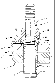
CA 02351467 2001-05-17
WO 00!36309 PCT/GB99/03862
The sleeve 21 (Figure 2) is generally cylindrical and is made of low carbon
steel. it has a through bore 22 of uniform diameter which is a sliding fit on
the pin
shank 12, and a cylindrical shank 23 which is of uniform external diameter. At
one
end (the tail end) the sleeve shank has a flat end face 24 and at the other
end (the
head end) an integrally formed radialiy enlarged head 25. The sleeve head
comprises a flange 26 having a flat annular underhead face 27. Formed
integrally
with the head flange 26 is a frangible element 28 in the form of a radially
projecting
flange which projects radially beyond the underhead face 27 and is also spaced
axially from the underhead face 27. As illustrated in Figure 2, the head
flange and
frangible flange have a common flat top face 29, but the frangible flange 28
is
thinner than the head flange 26, thereby producing the aforementioned axial
spacing between their lower faces, occupied by the outer circumferential face
31 of
the lower part of the head flange 26.
The sleeve shank includes a radially expandable portion which is centred on
a softened zone 19 which, as indicated in Figure' 2, in this example extends
axially
from a position about halfway along the length of the sleeve shank 21 to a
position
about three quarters of the way from the sleeve head 26 towards the sleeve
tail 24.
In this example, this softened portion 19 is made softer than the remainder of
the
sleeve by band annealing.
The abutment member (Figure 3) is in the form of a collar 32 made of low
carbon steel. It has a through bore 33 which is an interference fit on the pin
shank
12. As is common with collars of the AVDELOK (Registered Trade Mark) type of
fastener, the peripheral edge of the upper part of the collar has a bevel,
whilst the
lower end has a radially projecting flange 35. The bottom face 3C is flat, but
is
annular, since it is provided with a double recess 37. The recess 37 is
generally
4
CA 02351467 2001-05-17
WO 00!36309 PCTIGB99103862
circular on the axis of the collar, and comprises an outer recess 38 and an
inner
recess 39 of smaller diameter than the outer recess 38. The outer recess is of
a
diameter and depth suitable to receive the frangible flange 28 of the sleeve,
having
an annular bottom face 41 which surrounds the iinner recess 39. This inner
recess
has a diameter suitable to receive the circumferential face 31 of the sleeve
head,
and the total axial depth of the two recesses is rather greater than the total
axial
thickness of the sleeve head 25.
The pin, sleeve and collar are assembled together to form a fastener in the
way illustrated in Figure 4. The sleeve is assemkded on the pin shank 12 so
that the
sleeve end face 24 abuts the annular face of the pin head 13, and the collar
32 is
then assembled on the pin shank so that the annular recess face 41 abuts the
sleeve head top face 29 on the radially protruding annular upper face of the
frangible flange 28. The pin plain portion 17 protrudes from the top face of
the
collar 32. The collar is temporarily secured to the pin in this position by
its
interference fit on the pin shank, to prevent disassembly of the fastener
during
handling.
As also illustrated in Figure 4, the fastener is used to secure together two
structural metal panels 42, 43 which have a cylindrical aperture 44 through
them in
which the sleeve 21 is a clearance fit. In this example, the panels 42, 43
initially are
spaced apart by a gap 20, which the fastener will close up before it secures
the
panels together. The total thickness of the workpiece formed by the panels 42
and
43 and the gap 20, is rather more than half of the length of the sleeve shank
23, so
that the nearer end of the sleeve softened zone 19 indicated in Figure 1 lies
inside
the remote face 46 of the workpiece when the underhead face 27 of the sleeve
head contacts the near face 45 of the workpiece.
5
CA 02351467 2001-05-17
WO 00/36309 PCTIGB99I03862
The fastener is now installed by applying a progressively increasing pull to
the protruding part of the pin 11 in relation to the ;sleeve 21. This is done
by means
of a standard hydraulically-powered fastener placing tool, such as that
commercially
available under the designation AVDEL (Registered Trade Mark) Type 722, which
is
S used far installing pin and collar type fasteners presviously referred to.
The tool includes an annular anvil 47 (Figure 5) having an internal throat 48
shaped appropriately to swage the collar 32. The tool also includes jaws (not
shown) which engage with the pulling grooves ire the portion 18 of the pin,
and a
hydraulic piston and cylinder device (not sho4ron) for applying a
progressively
increasing retraction force to the jaws with respect to the anvil. Such tools
and their
manner of use are well known to those who use blind fasteners, and need not be
described in detail here.
The tool is offered up to the protruding part of the pin, so that the outer
end
of the anvil throat contacts the top of the collar 32: around its bevel 34, as
illustrated
i5 in Figure 5. The tool is then actuated so that its jaws engage the pulling
groove
portion 18 of the pin and exert a progressively increasing pull on it with
respect to
the anvil 47. This reaction force is transmitted through the collar 32 to its
recess
annular face 41; and thence via the face of the firangible portion 28 of the
collar to
the sleeve. The collar is thus axially compressed between the face of the
flange 28
and ifs end face 24 in contact with the pin head 13. The softened portion of
the
sleeve deforms by bulbing outwardly, to progres:~ively form a blind head in
contact
with rear face 46 of the workpiece. As the blind Izead progressively forms, it
exerts
a compressive force on the rear face 46 of rear panel 43, which urges the
panels
42, 43 together and so closes the gap 20 so that the panels are finally in
contact
with each other and compressed together betweein the sleeve head 25 and the
blind
6
CA 02351467 2001-05-17
WO 00136309 PCT/GB99/03862
head. The final form of the blind head, in this example, is illustrated at 49
in Figure
5.
The frangible flange 28 is strong enough to support the force needed to fully
form the blind head 49, but as the force on the collar 32 is further increased
the
frangible flange 28 shears off from the main body of the sleeve head 25. The
collar
32 is driven down the pin shank towards the workpiece. Since the flange 28 is
no
thicker than the collar's outer recess 38, the undf:rface 36 of the collar
contacts the
near face 45 of the workpiece, as illustrated in Figure 6. Since the collar's
inner
recess 39 and outer recess 38 have a total depth greater than the thickness of
the
sleeve head 25, there is a gap 51 above the sleeve head. Thus no axial loading
can be applied to the sleeve head by the collar. nonsequentiy, as the force
applied
by the installation tool continues to increase, all ~of the compression which
it exerts
is applied between the blind head 49 and the collar under face 36 to the
workpiece,
thus clamping the panels 42, 43 tightly together.
As the force applied by the tool further increases, the anvil 47 is pushed
down over the exterior of the collar; so that the anvil throat 48 swages the
collar 32
radially inwardly into the locking grooves 15 on the pin. The anvil stops with
its
lower face near the flange at the bottom of the collar. This position is
illustrated in
Figure 7.
Further increase of the force applied by the tool causes the pin to break at
the breakneck 16, the broken off pin tail being pulled away by the jaws,
leaving a
broken surface 52, as illustrated in Figure 8. They tool is then removed, to
leave the
installed fastener, as illustrated in Figure 9.
In certain circumstances it may be found that when the collar 32 is swaged
on to the pin by the tool anvil 47, material of i:he collar is extruded
towards the
7
CA 02351467 2001-05-17
WO 00136309 PCT/G899/03862
sleeve head 25. The modification shown in Figures 10 and 11 provides space to
accommodate such extruded material. The upper face 29 of the sleeve head 25 is
provided with a shallow conical recess 53, and the inner recess 39 at the
bottom of
the collar is provided with a shallow conical recess 54, as illustrated in
Figure 10
(which corresponds to Figure 4). Thus as illustrated in Figure 11 (which
corresponds to Figure 9) extruded material 55 from the collar is accommodated.
The fastener described in the foregoing example is advantageous over that
described in prior art EP 0705986 A in that it comprises less parts, and is
therefore
less expensive to manufacture and assemble. Furthermore, the prior art
fastener
initially forms its blind head spaced apart from the rear face of the
workpiece, and
then pulls the sleeve into the workpiece so that the blind head engages the
rear
face of the workpiece. This requires the provision of a sufficiently long
space within
the abutment member to accommodate the end of the retracted sleeve. The length
of retraction will increase with decreasing grip length. In the fastener of
the present
example, the blind head is formed in contact with the rear face of the
workpiece,
decreasing grip length and closure of any initial gap between the workpiece
members being accommodated by increasing radial extent of the blind head, so
that
the overall length of the fastener can be reduced compared with the prior art.
The invention is not restricted to the details of the foregoing example. For
instance, instead of the pin 11 being pulled into the sleeve 21 by a
retracting jaw
type of tool, it could be pulled in by a rotating nut arrangement similar to
that
described in EP 0705986 A. The abutment member 32 need not be permanently
secured to the pin 11 but could be removably secured thereta, for example by
means of a separate rotating nut arrangement, ass also described in EP 0705986
A.
8
CA 02351467 2001-05-17
WO 00/36309 PCT/GB99/03862
The separate nut could be avoided by making the abutment member itself in
threaded engagement with the pin.
The load at which the frangible element breaks can be controlled by
selecting the area over which is initially integral with the sleeve head, for
example
by selecting the thickness of the frangible element 28, or by providing an
annular
groove, of the same diameter of the sleeve head 25, in the top face or the
under
face of the frangible element 28.
The frangible element 28 need not be integral with the sleeve head 25, but
could be provided as a separate annular element, as also described in EP
0705986
A, although this would not be so advantageous in reducing the number of
components.
In use of the fastener described in the foregoing example, it is not essential
that the formation of the blind head is completed before breaking of the
frangible
member occurs, provided that it is completed before swaging of the abutment
member collar to the pin occurs.
9